Switched power to radio problem in an 87
#16
Under the Lift
Lifetime Rennlist
Member
Lifetime Rennlist
Member
Thread Starter
Thanks, Alan. If X works better, I could use the nearby cigar lighter wire as a source. I thought it was on the 15 bus, but it's shown as X (the first 5 fuse outputs). I found the short point in the wire from the switch and there is no power at that point, so that's why I was suspecting the switch. I'll test the switch later. Thanks to everyone for the help.
#17
Under the Lift
Lifetime Rennlist
Member
Lifetime Rennlist
Member
Thread Starter
So what does a current owner do to rewire the HU in correctly when the PO has the wiring totally screwed up but the original wires are still present?? I don't follow where the signal wire hooks into an aftermarket HU if the 12V are coming from the other wire. Please forgive my questions if they seem dumb, I am just trying to figure this out so that I can make mine right.
#18
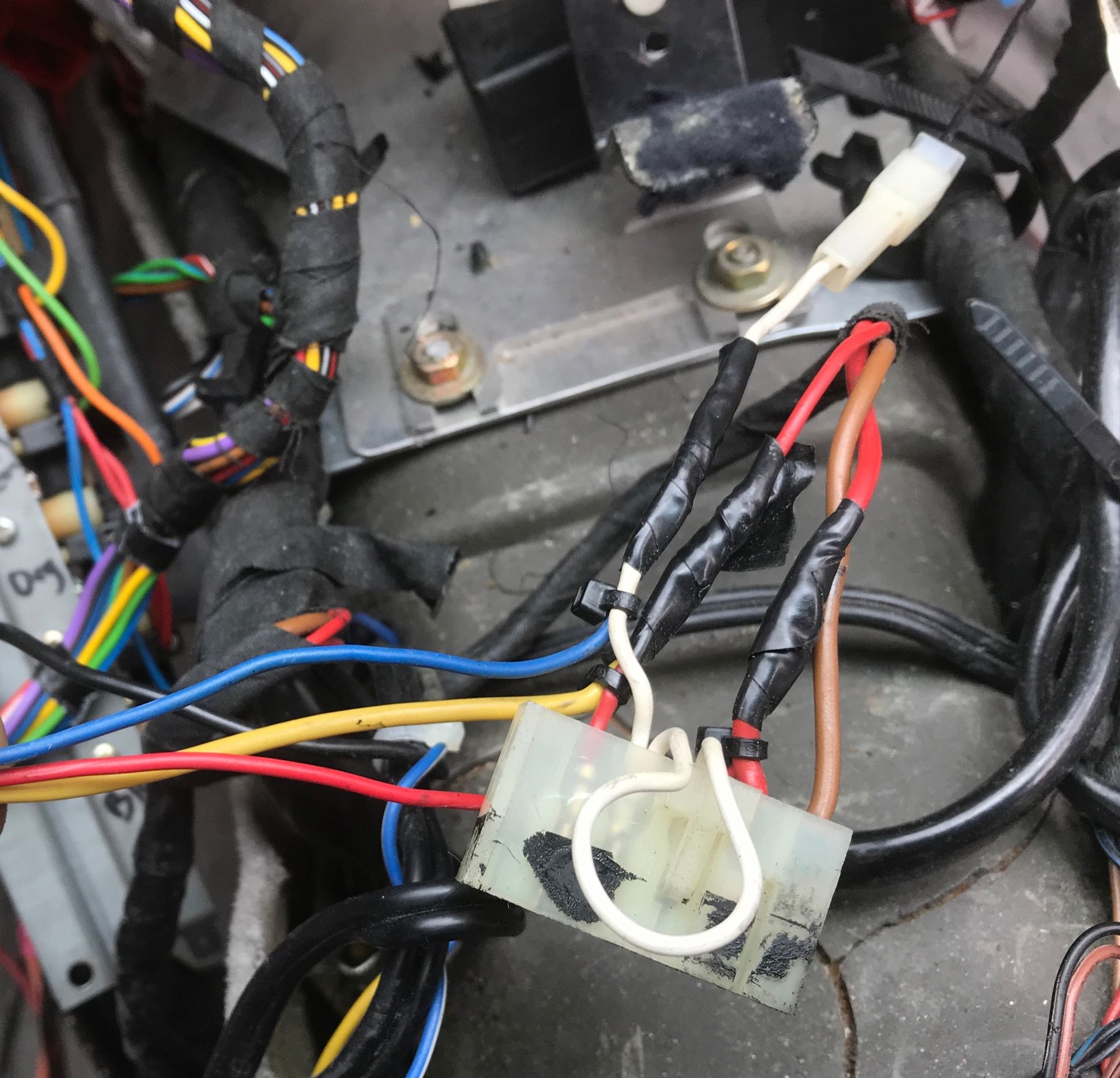
In this 87 there is a wrapped wire bundle of 3 wires behind the radio: two red wires, one brown. The connector had been cut-off but yours may not have. Anyway, brown is ground and one of the reds is constant 12V while the other is signal 12V controlled by the ignition switch. A voltmeter will help sort that. The instructions for wiring the radio should tell which wire on its harness is for which of these 3 power-related wires. On this Apline radio they are on a sticker on the top of the radio. If not, you can usually find wiring manuals at the manufacturer's site or elsewhere via Googling the make and model. That's the extent of my electrical knowledge.
Thanks for answering my questions. I really appreciate everyone's patience while I catch up on the learning curve!

#19
Under the Lift
Lifetime Rennlist
Member
Lifetime Rennlist
Member
Thread Starter
Usually the constant power and signal power wires on the radio are yellow and red, although they may be the opposite or other colors. Look at the existing wires to the radio and test them with a voltmeter until you find the one that is constant 12V regardless of ignition position, then look for a wire that has 12V only when the ignition is on. Test that 3 wire bundle too to make sure it hasn't been cut somewhere.
#21
Electron Wrangler
Lifetime Rennlist
Member
Lifetime Rennlist
Member
Yep, I have the three wire (2 red and a brown) bundle. They were all bypassed when the PO put in the current stereo by jumping straight to the fuse/relay box, but they are still there. My current stereo is a very old (Cassette era) Sony, and I have the owners manual, but no wiring diagram. I have scoured the web for a wiring diagram for it to no avail. I understand the basics of stereo installation and wiring, but where does the signal wire hook in? I can't tell that my Sony has anywhere to attach a signal wire that would activate the stereo. Is it just too old and a new one would have one??
Thanks for answering my questions. I really appreciate everyone's patience while I catch up on the learning curve!
Thanks for answering my questions. I really appreciate everyone's patience while I catch up on the learning curve!

On an older unit you may need to use the antenna power out for an amplifier trigger control. For the head unit look at other similar era Sony docs you will probably find the connectors are common - if there is a connector/pigtail with colored wiring (typical) the color will also be common to all other Sony's of same era. Most likely Switched Power will be a Red wire and Constant power a Yellow wire. Amp trigger or Antenna Power wires will usually be Blue, Illumination control Orange and Ground Black
Of course VMMV...
Alan
#22
Under the Lift
Lifetime Rennlist
Member
Lifetime Rennlist
Member
Thread Starter
Alan, I took one of those piggyback (double spade) adapters and put it on the cigar lighter spade with the new extra wire headed back to the noise suppresor for the radio trigger. Working well.
#23
Addict
Lifetime Rennlist
Member
Lifetime Rennlist
Member
In this 87 there is a wrapped wire bundle of 3 wires behind the radio: two red wires, one brown. The connector had been cut-off but yours may not have. Anyway, brown is ground and one of the reds is constant 12V while the other is signal 12V controlled by the ignition switch. A voltmeter will help sort that. The instructions for wiring the radio should tell which wire on its harness is for which of these 3 power-related wires. On this Apline radio they are on a sticker on the top of the radio. If not, you can usually find wiring manuals at the manufacturer's site or elsewhere via Googling the make and model. That's the extent of my electrical knowledge.
a bump.
was searching as i was sorting my POs wiring from 20+ yrs ago. Just trying to clean things up on my radio while its all gutted.
this is the connector Bill is referencing.
white appears to be for the antenna..
brown...ground
two reds ..power.


