
Twin Turbo 928 fixed and back out there terrorizing the streets!
 10-23-2013, 05:16 PM
#691
Nordschleife Master
Thread Starter
At this point, it looks that only the compressor outlet needs to be cut off and new piece welded in. The compressor inlet can probably stay as is, since it's the "Skyline" cover.
Here's how the smaller turbos are done:
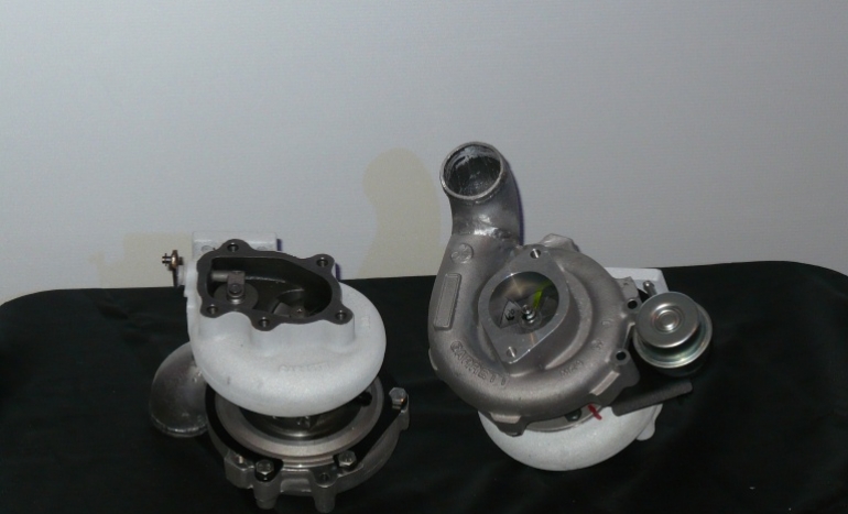
The compressor inlet and outlet have to both point forward for this to work.
Here's how the smaller turbos are done:
The compressor inlet and outlet have to both point forward for this to work.
 10-28-2013, 05:02 PM
#692
Nordschleife Master
Thread Starter
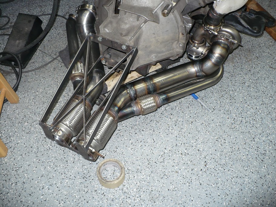
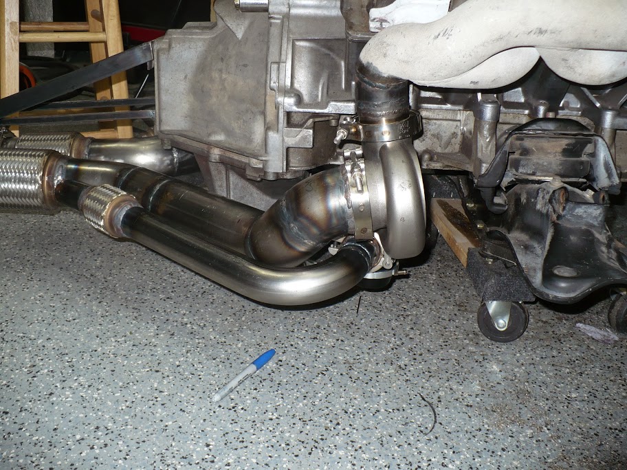
Here are two photos of how the passenger side turbine piping was designed. This is pretty much the complete story on the hot side:
10-28-2013, 10:45 PM
#694
Addict
Rennlist Member
Rennlist Member
Join Date: Oct 2003
Location: Gone. On the Open Road
Posts: 16,489
Received 1,636 Likes
on
1,067 Posts
"... kindof a prerequisite; you need to be able to steer the car after you put all this in..."
LOL.
Looking good Tuomo.
LOL.
Looking good Tuomo.
10-29-2013, 09:20 AM
#695
Supercharged
Rennlist Member
Rennlist Member
Join Date: May 2002
Location: Back in Michigan - Full time!
Posts: 18,925
Likes: 0
Received 60 Likes
on
34 Posts
I'm glad you mentioned the steering, because visually, it looks like the steering shaft wont clear. That is going to be a beast. Great work. Keep it going.
10-29-2013, 09:45 AM
#696
Nordschleife Master
Thread Starter
The goal of this R&D project is to have fun and see how the stock engine breaks. However, it would also be nice to create a system that can flow a lot of air for a lot of hp, while still requiring no body modifications or relocation of major components such as the steering shaft. The less extensive the modifications that are required, the greater the number of people who can realistically enjoy this system.
11-09-2013, 02:48 PM
#698
Nordschleife Master
Thread Starter
Been looking at other people's turbo oiling designs and talking to John trying to figure out what to do in the short run and in the long run.
On the turbo pressure side, we need to lower the oil pressure. Ball bearing center housing requires a much lower pressure than the 8 or so bars that the '87 S4 has at the filter inlet. In the short run, this will be done with a restrictor in each line. In the long run, if we start adjusting the main engine oil pressure, we'll probably add a bypass regulator, which allows one to change the engine oil pressure without changing the restrictor.
On the turbo drain side, we can currently fit only one electric scavenge pump next to the clutch cylinder. There are smaller pumps, but this is the smallest pump that I know of that has the right capacity and is rated for 10,000 hours of continuous duty at engine oil temperatures.
Trying to scavenge two turbos with one pump results in the age old "drinking milkshake with a hole in the straw" problem. The solution to this problem is two large-capacity turbo oil drain sumps. With two sumps, the turbo oiling should function >30 seconds of >1g lateral acceleration in one direction. As one transitions from a turn, the pump quickly empties the sump that was on the turn outside. There aren't many situations in which I plan to turn for more than 30 seconds in the same direction at >1g so this meets my requirements. In the long run, I might try to come up with a second pump stage so one can ditch the sumps.
As the pump pulls thru much more fluid than the turbos will supply, we need to allow replacement fluid to fill the sumps. The innovation in this round of development is that we'll source the replacement fluid from ProVent oil drain. This creates an active scavenging of ProVent oil drain, which by my logic will significantly improve the oil separation efficiency of ProVent separator. Well, efficiency is probably the wrong word -- more accurately, make it less likely that any oil will ever come out of ProVent gas outlet port.
The turbo scavenge pump will return the oil-air mixture to the oil pan front sump near the oil fill level. This will allow air and oil to separate relatively easily.
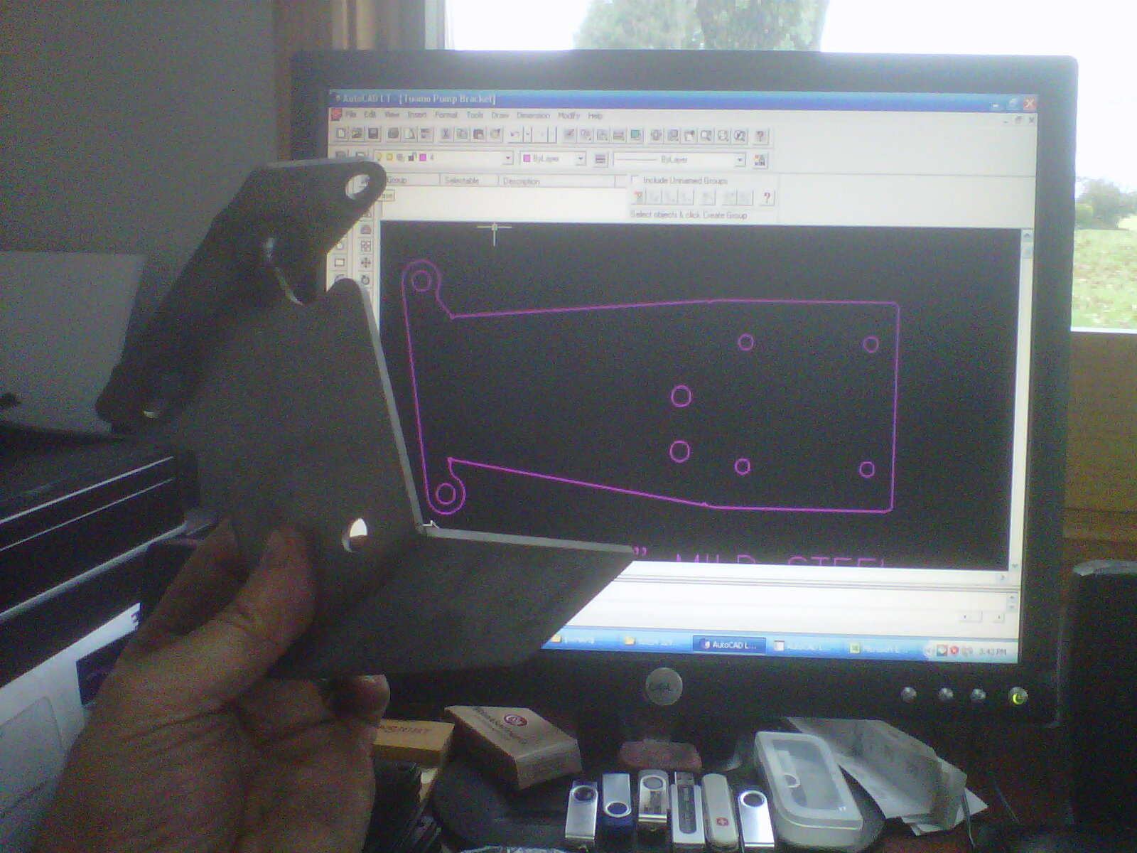
On the fabrication side, John's designing the bracket for the new pump. See the below photo. He's also decided to go for 3" sumps. The new turbos are a bit lower, so the sumps will be a bit shallower. To get the same volume as with the old sumps, the diameter has to be increased. He's planning to get the sumps done by the end of the week.
On the turbo pressure side, we need to lower the oil pressure. Ball bearing center housing requires a much lower pressure than the 8 or so bars that the '87 S4 has at the filter inlet. In the short run, this will be done with a restrictor in each line. In the long run, if we start adjusting the main engine oil pressure, we'll probably add a bypass regulator, which allows one to change the engine oil pressure without changing the restrictor.
On the turbo drain side, we can currently fit only one electric scavenge pump next to the clutch cylinder. There are smaller pumps, but this is the smallest pump that I know of that has the right capacity and is rated for 10,000 hours of continuous duty at engine oil temperatures.
Trying to scavenge two turbos with one pump results in the age old "drinking milkshake with a hole in the straw" problem. The solution to this problem is two large-capacity turbo oil drain sumps. With two sumps, the turbo oiling should function >30 seconds of >1g lateral acceleration in one direction. As one transitions from a turn, the pump quickly empties the sump that was on the turn outside. There aren't many situations in which I plan to turn for more than 30 seconds in the same direction at >1g so this meets my requirements. In the long run, I might try to come up with a second pump stage so one can ditch the sumps.
As the pump pulls thru much more fluid than the turbos will supply, we need to allow replacement fluid to fill the sumps. The innovation in this round of development is that we'll source the replacement fluid from ProVent oil drain. This creates an active scavenging of ProVent oil drain, which by my logic will significantly improve the oil separation efficiency of ProVent separator. Well, efficiency is probably the wrong word -- more accurately, make it less likely that any oil will ever come out of ProVent gas outlet port.
The turbo scavenge pump will return the oil-air mixture to the oil pan front sump near the oil fill level. This will allow air and oil to separate relatively easily.
On the fabrication side, John's designing the bracket for the new pump. See the below photo. He's also decided to go for 3" sumps. The new turbos are a bit lower, so the sumps will be a bit shallower. To get the same volume as with the old sumps, the diameter has to be increased. He's planning to get the sumps done by the end of the week.
Last edited by ptuomov; 11-19-2013 at 09:50 PM.
 11-19-2013, 10:08 PM
#701
Nordschleife Master
Thread Starter
A quick word about why these new turbos are needed. Recall that we hit a sonic choke at the turbine blades. What that means that the mass air flow thru the compressor was maxed out. This in turn would have meant that no matter whether we'd switched to race gas, fabricated a new intake manifold, put in a lot bigger cams, stroked the engine, installed open one-foot exhaust test pipes; we would have not made more than 700 rwhp. Basically, we could hit 680 rwhp at slightly above 4700 rpm, and after that the best case scenario was to improve high-rpm efficiency to keep the power at 700 rwhp to engine redline. That was the max, no matter how much $$$ we would have thrown at the base engine.
With these new, larger, "surgically improved" turbos we're hoping to restore the situation in which we can actually get some benefit from bigger cams and slightly tweaked intake port and manifold runners. The low compression engine waiting to be installed has those, and it would have made no sense to swap out the stock engine before we can feed the low-compression engine.
With these new, larger, "surgically improved" turbos we're hoping to restore the situation in which we can actually get some benefit from bigger cams and slightly tweaked intake port and manifold runners. The low compression engine waiting to be installed has those, and it would have made no sense to swap out the stock engine before we can feed the low-compression engine.
Last edited by ptuomov; 11-20-2013 at 12:02 AM.
11-20-2013, 12:29 AM
#702
Nordschleife Master
Been looking at other people's turbo oiling designs and talking to John trying to figure out what to do in the short run and in the long run.
On the turbo pressure side, we need to lower the oil pressure. Ball bearing center housing requires a much lower pressure than the 8 or so bars that the '87 S4 has at the filter inlet. In the short run, this will be done with a restrictor in each line. In the long run, if we start adjusting the main engine oil pressure, we'll probably add a bypass regulator, which allows one to change the engine oil pressure without changing the restrictor.
On the turbo pressure side, we need to lower the oil pressure. Ball bearing center housing requires a much lower pressure than the 8 or so bars that the '87 S4 has at the filter inlet. In the short run, this will be done with a restrictor in each line. In the long run, if we start adjusting the main engine oil pressure, we'll probably add a bypass regulator, which allows one to change the engine oil pressure without changing the restrictor.
11-20-2013, 05:45 PM
#703
Nordschleife Master
Thread Starter
Hydraulic stores will have a pressure limiting valve. Take a -4 or -6 oil line off the oil filter as you are doing, then plumb that into the pressure limiting valve, and adjust the outlet pressure to whatever pressure you want, without having to worry about it going over, OR reducing the rest of the system pressure.
11-23-2013, 03:51 PM
#705
Nordschleife Master
Thread Starter
The sumps have been test fitted now, as well as the turbo oil drain scavenge pump:
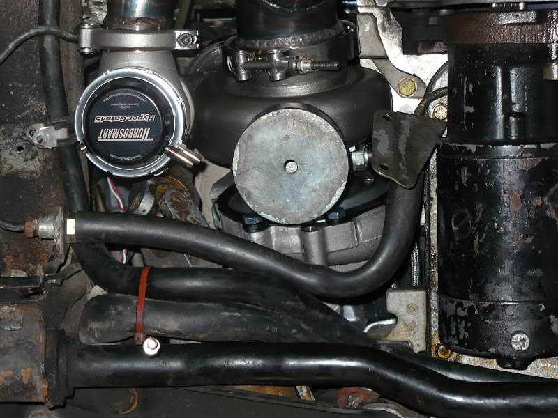
The sumps are cylinders, slightly offset from the center housing oil outlet to provide maximum clearance in every direction. The turbine housings will be thermal barrier coated white like the old turbos. The sumps, in contrast, will be coated with a black thermal dispersant.
Each one has a hole in the bottom, that'll be threaded for a drain plug. This way, one can change the oil without removing the sumps.
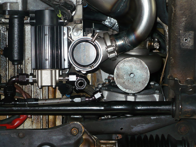
The passenger side also shows the pump and the bracket. As you can see, there's no room for a second pump. There's no room for anything in there, to be frank. It's completely packed, there is pretty much nothing more that can be fitted under the hood.
The pump system scavenges two pick-up points with one pump. That's why the sumps are needed. Basically, the sump only pumps oil when the t-fitting visible in the passenger side photo is submerged with oil. When the t-fitting is no longer submerged with oil, then the pump sucks air. The sumps make it so that with forward and backward accelerations the t-fitting is submerged and during cornering the outside turbo can drain to its sump.
The pump is a nice piece. It's rated for a high temperature (350F fluid temperature when pumping engine oil) and many, many hours. The gears are angle cut so it's reasonably quiet. The heat sink with fins will help with cooling the pump. The pump is also powerful enough to quickly empty the sumps, which is convenient at shutdown. The pump operates based on logic that drives of the key ignition position and the open/close state of the driver side door. This logic automatically empties the ProVent and the sumps when the car is parked. (In contrast, the electric water pump that cools the turbos always runs for five minutes after shutdown. This is to extend the turbo life.)
The sumps are cylinders, slightly offset from the center housing oil outlet to provide maximum clearance in every direction. The turbine housings will be thermal barrier coated white like the old turbos. The sumps, in contrast, will be coated with a black thermal dispersant.
Each one has a hole in the bottom, that'll be threaded for a drain plug. This way, one can change the oil without removing the sumps.
The passenger side also shows the pump and the bracket. As you can see, there's no room for a second pump. There's no room for anything in there, to be frank. It's completely packed, there is pretty much nothing more that can be fitted under the hood.
The pump system scavenges two pick-up points with one pump. That's why the sumps are needed. Basically, the sump only pumps oil when the t-fitting visible in the passenger side photo is submerged with oil. When the t-fitting is no longer submerged with oil, then the pump sucks air. The sumps make it so that with forward and backward accelerations the t-fitting is submerged and during cornering the outside turbo can drain to its sump.
The pump is a nice piece. It's rated for a high temperature (350F fluid temperature when pumping engine oil) and many, many hours. The gears are angle cut so it's reasonably quiet. The heat sink with fins will help with cooling the pump. The pump is also powerful enough to quickly empty the sumps, which is convenient at shutdown. The pump operates based on logic that drives of the key ignition position and the open/close state of the driver side door. This logic automatically empties the ProVent and the sumps when the car is parked. (In contrast, the electric water pump that cools the turbos always runs for five minutes after shutdown. This is to extend the turbo life.)