When you click on links to various merchants on this site and make a purchase, this can result in this site earning a commission. Affiliate programs and affiliations include, but are not limited to, the eBay Partner Network.
All the clamps on the pressure-side of the Turbos, the ones used on the induction path to the motor. In my experience, the worm gear clamps will fail under the kind of pressure you will be demanding of them. T-bolt clamps are designed for the higher pressures, and do come with constant-tension springs if you feel that is needed. I have found that the springs are not necessary on my boost levels (up to 20 psi), which I am glad about because they are a bit biggish and cumbersome. If you want, I can post an example picture if you like.
All the clamps on the pressure-side of the Turbos, the ones used on the induction path to the motor. In my experience, the worm gear clamps will fail under the kind of pressure you will be demanding of them. T-bolt clamps are designed for the higher pressures, and do come with constant-tension springs if you feel that is needed. I have found that the springs are not necessary on my boost levels (up to 20 psi), which I am glad about because they are a bit biggish and cumbersome. If you want, I can post an example picture if you like.
Does the steel clamp literally fail or does the coupling disconnect in your applications? It's not visible from the photos, but the pipes have a rolled bead sort of an expansion right at the end. The silicone boot ends up between the pipe expansion and the clamp. For pipes of this diameter, this connection with these clamps appears to be very robust. The pipe diameter is key, as the force that pulls the pipe out from the coupling is proportional to boost pressure and the pipe diameter squared.
Here's the rolled bead on a steel pipe. At 2.5" or so diameter, a silicone boot held with a steel worm clamp with rounded edges will basically never come off at any relevant pressure for these pipes. It also doesn't want to cut thru the silicone boot because the pipe and the clamp thermal expansion coefficients match approximately and the temperatures aren't that extreme.
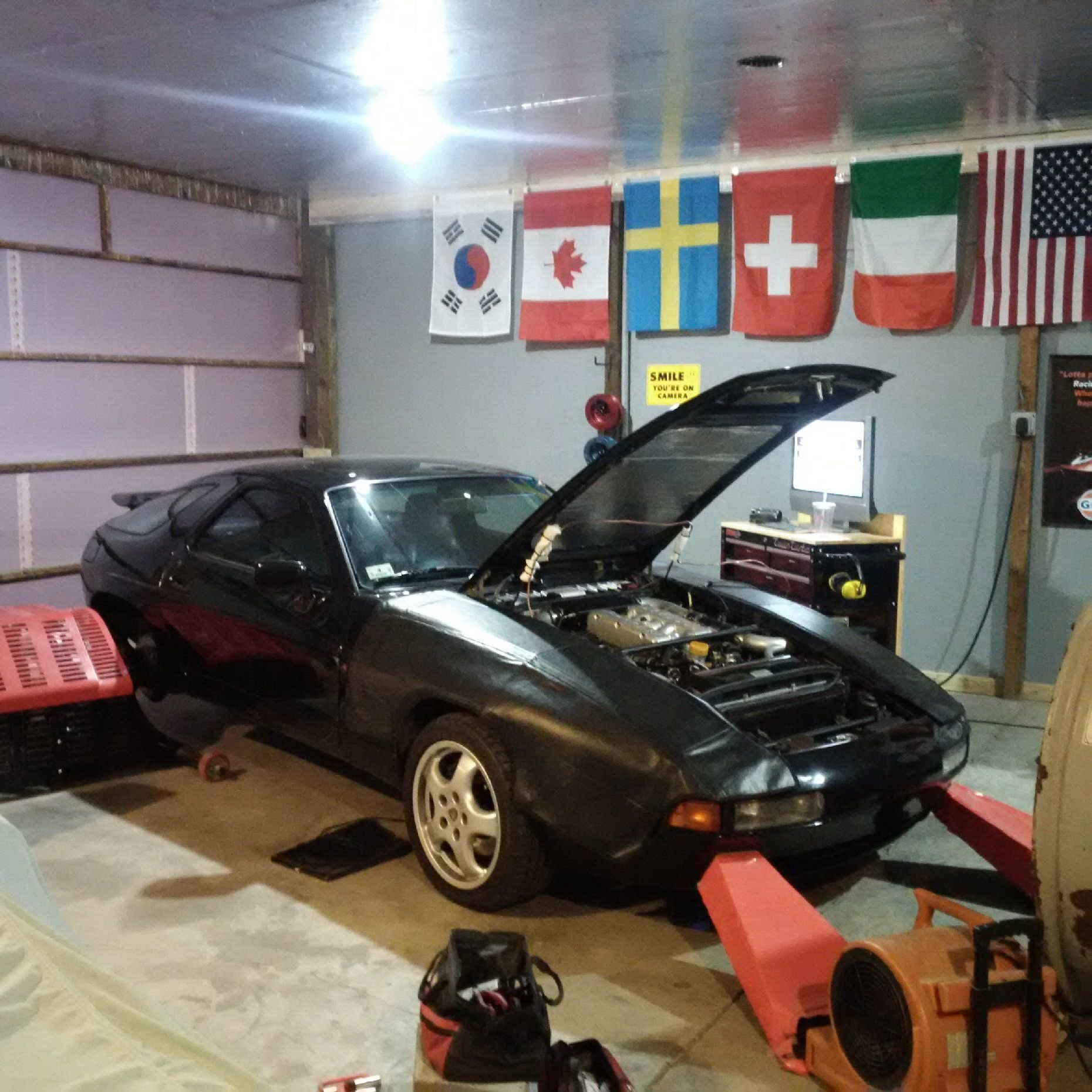
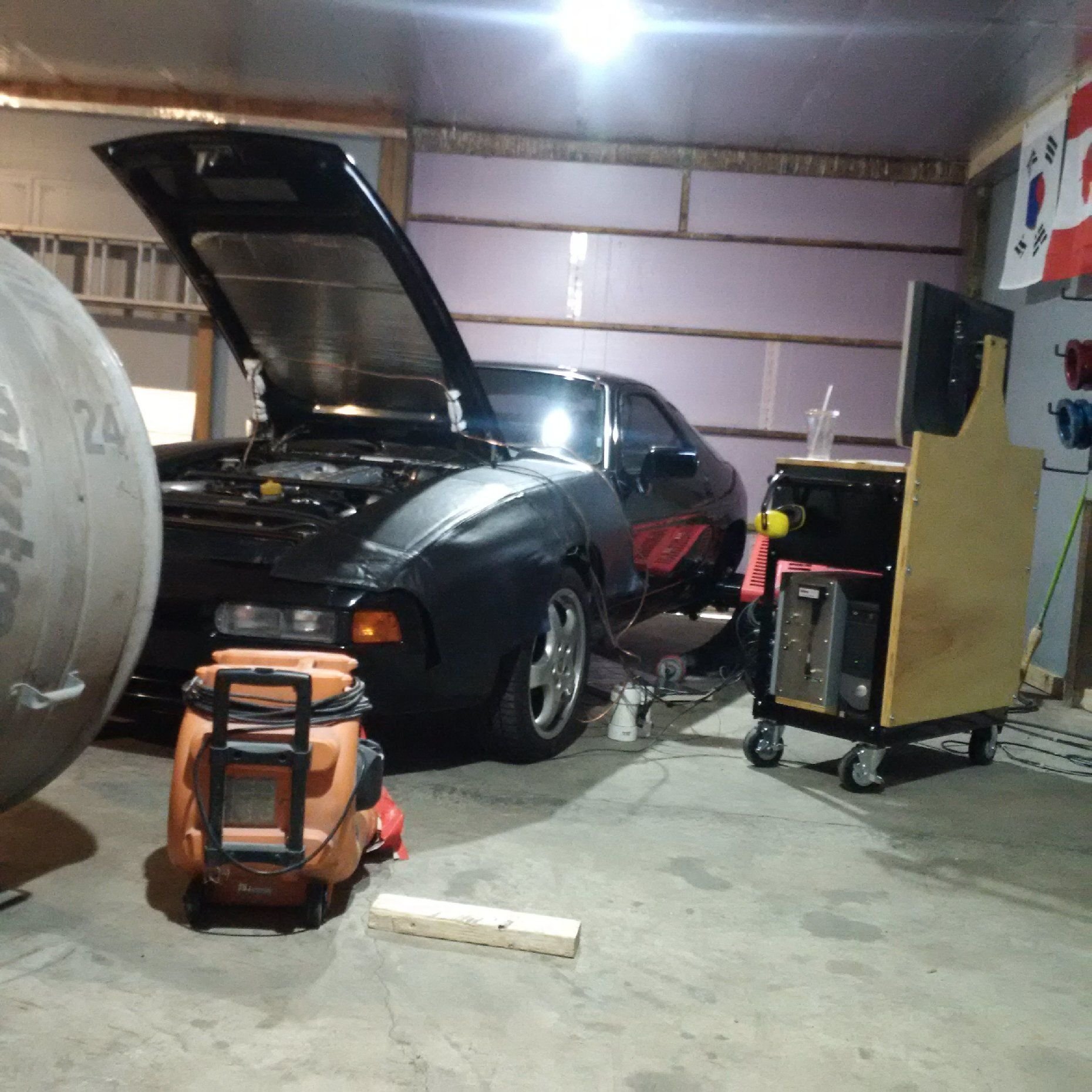
Strapped on the dyno. John’s dyno shed has been upgraded since last year:
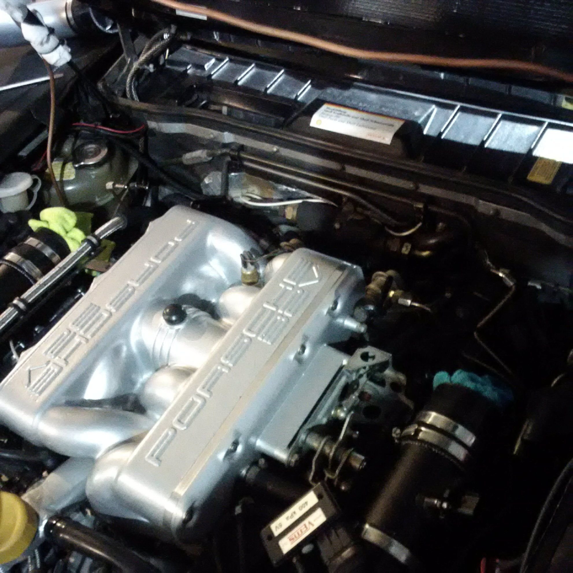
Those pots are to protect the exhaust manifold and downpipe pressure sensors. They are still the slow sensors, but hot condension water ruins them. Therefore, one needs those traps for condension water. Since it's not trying to get the pressure by crank degree but just a cycle average pressure, the line length and traps don't matter. The delay is by speed of sound and for the cycle averages it therefore doesn't matter.
That run was about 590 rwhp at 6300 rpm. 12.5 psig and AFR is like 11.2 so it's a little phat still and not making as much it could at this boost level.
The exhaust sounds good and doesn�t pop on deceleration even though there�s a little blue flame there. The idea in that muffler was to cool and expand the exhaust gas, allow for gradual mixing of cool air into the exhaust, and preheating of the outside air that comes to contact with the exhaust gas. Working well.
Instead of squeezing more out with the current SS digital MAF emulator, John will now swap in the custom analog MAF emulator built for us by JDS. Once that runs as expected, the real tuning will proceed.
Thanks for sharing. Interesting numbers so far. I look forward to what you end up with. If you're willing to share the final #'s, I would love to see boost pressure, intake temperatures, and AFR along with the power output.
The splits/Y's in the intake next to the fenders, I assume those go to blow off valves?
Correct, the smaller pipes go to bypass valves.
That dyno run was just a rich and retarded shakedown run. I posted it for the sound as it’s an opportunity the heat the new exhaust at high rpms. It's about 40hp off where it will be at that boost once the tune is on.
Getting any sort of meaningful power numbers is going to take weeks because the underlying base maps in LH that seek to hit 14.7 AFR need to be recalibrated for the dual MAFs. The transmission failure interrupted that effort last year.
What are the stock S4
(1) lobe offset (I think 2mm)
(2) lobe taper (I think 0.05-0.15 degrees)
(3) lifter dome radius (I think > 300cm if any)
(4) lifter bore to lifter bore clearance (no guess)
?
I�m trying to figure out how the hell the valvetrain geometry is supposed to work in 928 S4.
I had a chance to ask Mike Jones of Jones Cams about the flat lifter cam setup. Simard's 7L engine, for example, runs his cam lobe profiles. I learned something, not the least that I still have a lot to learn! Posted here with a permission.
by CamKing
If the lobe has taper, you need to run a bucket with a crowned face.
If the lobe has no taper, you have to run a bucket with no crown on the face.
The offset between the lobe and the bucket will make the bucket rotate. It doesn't need any taper.
99% of all the bucket follower cams we have made for the last 40 years, including Cosworth, Porsche, Ferrari, Lamborghini, VW, GM, Ford, Nissan, Toyota, and H-D, run no taper, and no crown.
by ptuomov
Some measurements:
The various water-cooled transaxle Porsches from the 1970's to 1990's that we've measured all have tapered cam lobes from the factory. The lobe widths are around 12mm for the four valve variants and the taper is 0.02-0.03mm over that length. By my math, that computes to about 0.05-0.15 degree taper for stock cams. This is repeatable and measured by a number of people.
Some people have measured a crown on the original lifters installed at the factory. The crown measurements indicate 300cm to +Inf (i.e., completely flat) radius for those. The old original lifters that I've measured are completely flat to my measurement abilities. The new "genuine" Porsche lifters sold as spares are flat to my measurement abilities.
I don't fully understand why they put a taper on a cam lobe that is 2mm offset from the lifter and runs on an essentially flat lifter. Any ideas?
by CamKing
No. I assume the lifters were all supposed to have a small crown (300cm sounds about right), and somewhere that was mistakenly changed.
If you run taper and a flat lifter. The edge of the lobe is all that touches the lifter, and will prematurely wear.
If you run taper and a crowned lifter, the contact point is between the edge and the center of the lobe.
The offset is just to make sure that contact point is off-center on the lifter, so it'll spin.
BTW, the Cayenne cams are flat lobes, and no crown on the lifters.
by ptuomov
These are in the pre-Cayenne 928/944/968 etc. engines.
There's some sort of screw-up there by someone, be that measurement, design, factory, or aftermarket...
928 factory cams don't wipe out / wear lifters in 200k miles, even when its tapered cams and flat no-crown lifters coming out of the engines. Why? To the extent that they have some damage, it's pitting on the cam nose that is not biased to one side, very even. Not what I'd expect from a tapered cam lobe running on a flat lifter. What's going on?
One thing I am thinking about is that the lifter rocks in the lifter bore because of the cam offset causing a rocking force. This may allow even a flat no-crown lifter to run parallel with a tapered lobe. Does that make sense?
by CamKing
It could rock, but then the contact point on the valve tip would be to one side.
It may just be, that the spring pressure is so low, that having the wrong setup isn't hurting anything.
I've seen cams that were supposed to be flat, survive with .0005" taper on the lobes. Even some roller cams.
Just because they're living, doesn't mean they're correct.
There is zero reason to run a tapered lobe on a non-crowned lifter, unless the valve/follower are not perpendicular to the cam.
by ptuomov
Thank you, this is very useful.
Final question. Given the camshaft lobe taper, how does one determine the optimal lifter crown radius? Just taking the taper degrees and the camshaft offset and then geometrically computing the radius that places the contact point at the center of the lobe gives a radius that is much smaller than what the car factories have actually used in recent decades. What's the design equation they use to relate lifter crown radius, camshaft offset, and cam lobe taper?
by CamKing
I don't think you want the contact point in the center of the lobe. You want it between the center and the edge.
I don't know the equation. I've drawn it out a couple times, but that was just for contact on the base circle.
When you look at the wear pattern on a tapered lobe, that runs against a crowned lifter. The contact point starts near the center of the lobe(on the base circle, but as you accelerate up the lobe, the pattern moves towards the edge of the lobe, then back towards the middle as it reaches max lift.
by ptuomov
Thank you. For practical purposes, it'll be "no taper cams" on "flat lifters" from now on.
The car is back in pieces. John is taking out the SS box and installing JDS�s custom analog box. It�ll be interesting to see how close the maps will be.
The car is now running with the JDS dual MAF analog voltage processing circuit. I wouldn't be shocked if this dual MAF + analog voltage processing setup would have some uses for other people as well.
Connector is temporary, dyno cell has some new pressure sensors. The final connector will come out of 3D printer at some point.
Right now, it's good enough to run as it is.


 07-22-2019, 02:03 PM