
Timing Belt and Water Pump Procedure w/pics
 01-02-2010, 07:07 AM
#31
Rennlist Member
Wayne, as usual this is a brilliant write up !
I would suggest that you include the tightening torque for the radiator drain plug which is 1.5Nm or 1.1ft/lb. It is easy to break the head off if over tightened. As you say, the seal is due to the O ring on the shank of the bolt, not under the head of the screw.
The part number of the flywheel lock tool is 9161/1 for the later engines (MY 83 and later.)
 01-02-2010, 12:55 PM
#32
Three Wheelin'
Thread Starter
Join Date: Sep 2007
Location: Ridgecrest, California
Posts: 1,363
Likes: 0
Received 147 Likes
on
31 Posts
If you haven't already, you will need to clean the water pump gasket surface on the engine block. A gasket scraper works well for this.
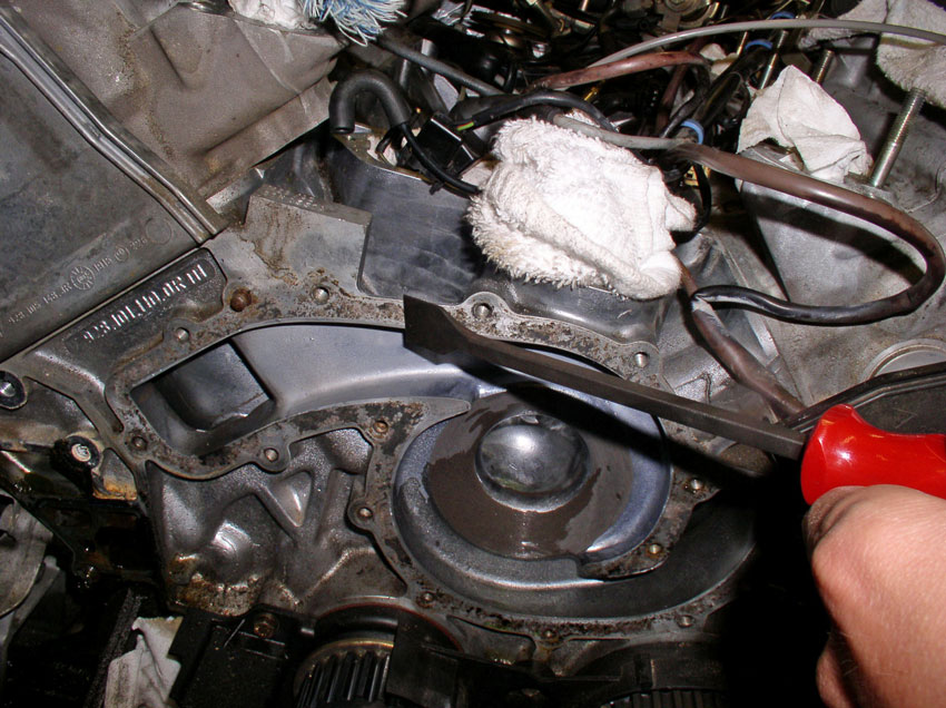
In addition, you will need to clean the timing belt tensioner gasket off the block as well as we will be installing the tensioner in the next section.
After the block surface has been cleaned, install the new water pump gasket. I have installed gaskets both dry and with water pump gasket sealant. Both methods seem to work well. I would only recommend sealant (applied to the block surface and the water pump surface) if you have damaged surface areas that would cause a leak. The WSM does not recommend sealant so I usually install the gaskets dry and have had good luck.
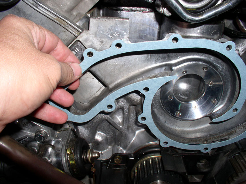
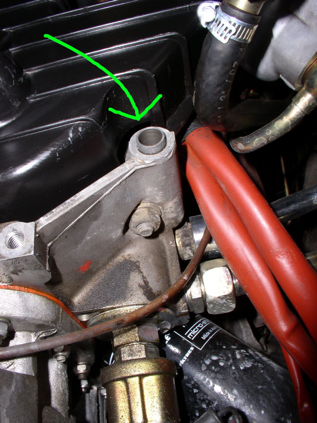
There are cutouts in the gasket that match up with the locating pins on the block (highlighted in the pic below). This makes it handy to hold the gasket in place while you install the pump.
Install the pump next and press it into place over the locating pins. The pins should hold the pump in place while you insert and hand tighten the water pump bolts. This procedure will vary slightly depending on whether you have a rebuilt water pump or a brand new water pump to install. Pictured below is a brand new water pump.
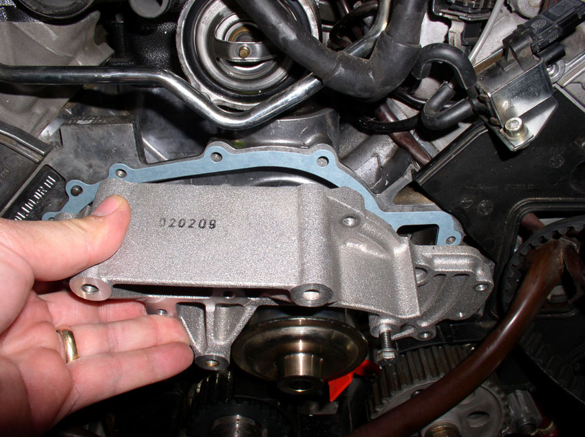
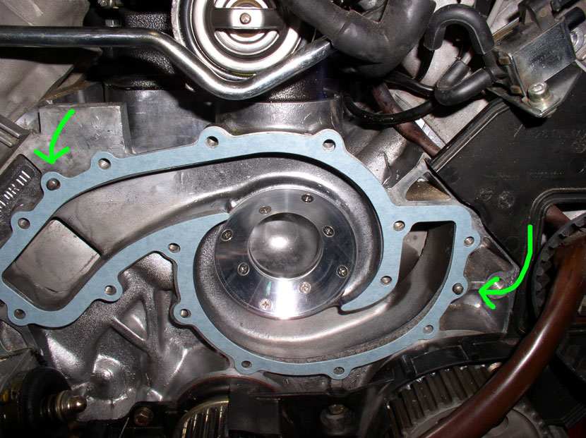
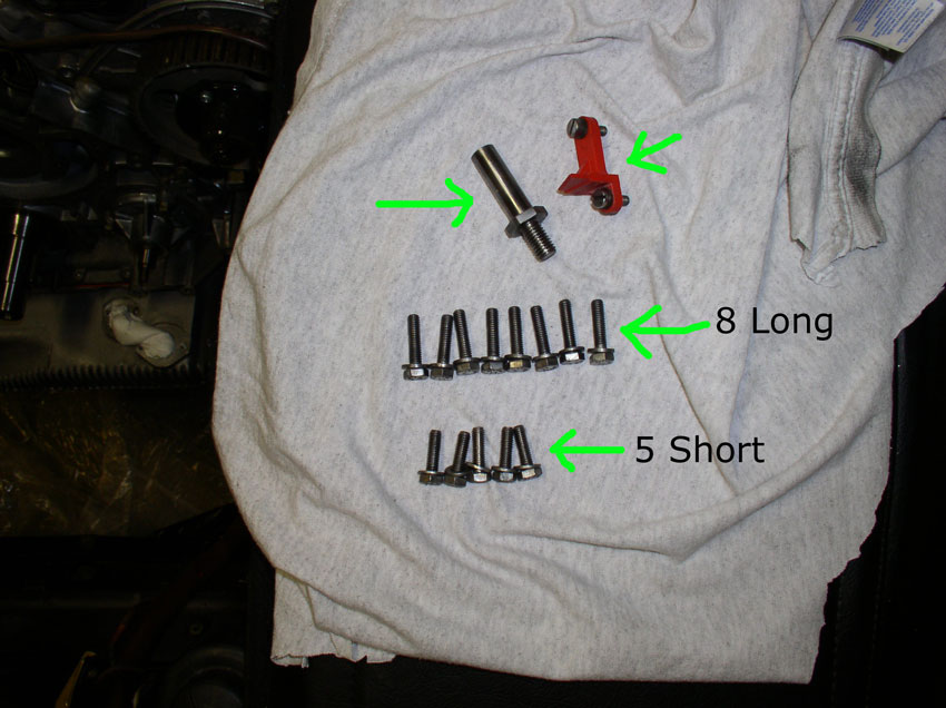
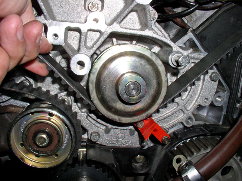
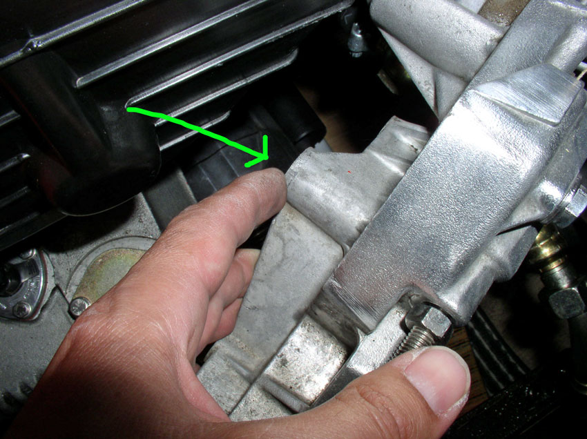
If you purchased a rebuilt water pump, you will most likely need to transfer the red plastic timing marker and the tensioner pulley spindle (indicated by the top two arrows in the pic below) from your old water pump to the newly rebuilt water pump. If you purchased a new water pump, both of these items should come already installed on the water pump. As mentioned previously, there are 13 water pump bolts that need to be installed at this time. Eight (8) are long and five (5) are short. The shorter bolts fit in the recessed areas of the pump housing.
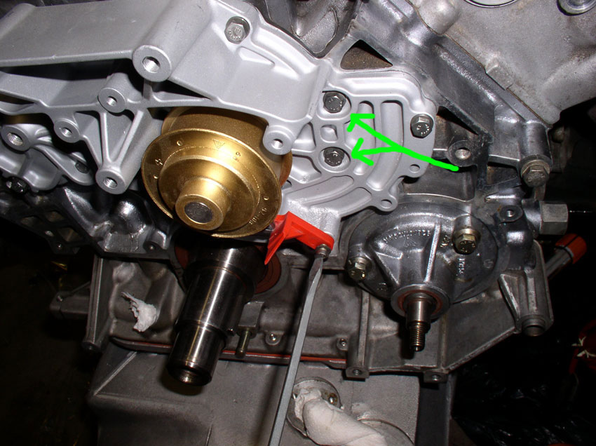
The picture below shows a rebuilt water pump being installed and you would install the red timing marker as depicted below. Also highlighted are 2 of the 5 recessed areas for the water pump bolts. There are two of these on the right side of the water pump pulley (as shown below) and the other 3 are on the left side of the water pump pulley.
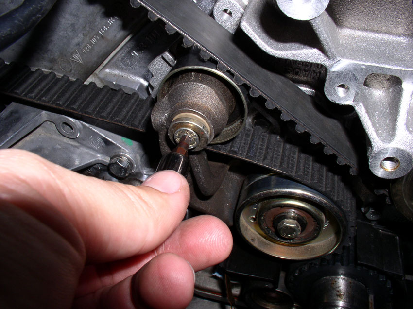
Again, with the rebuilt pump, you will need to transfer the timing belt tensioner pulley spindle to the newly rebuilt pump. You will need to coat the threads with water pump gasket sealant as shown below. The sealant is available at most auto parts stores. You need to coat the threads before installing the spindle since the spindle threads go all the way through the water pump and you will have a coolant leak without coating these threads.
Tighten the spindle down with a 19mm wrench. If you purchased a new water pump with the spindle already installed, this step is not necessary.
If you purchased a new water pump (as pictured below), you will simply bolt the pump on. In either case (new or rebuilt), hand tighten all 13 bolts. I hand tightened using the 10mm socket and extension bar only.
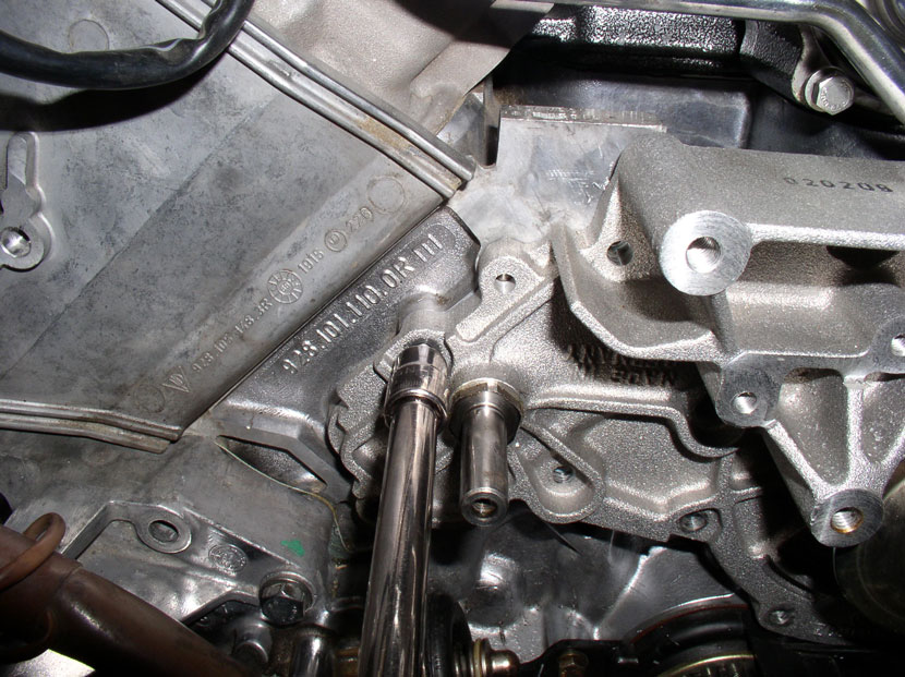
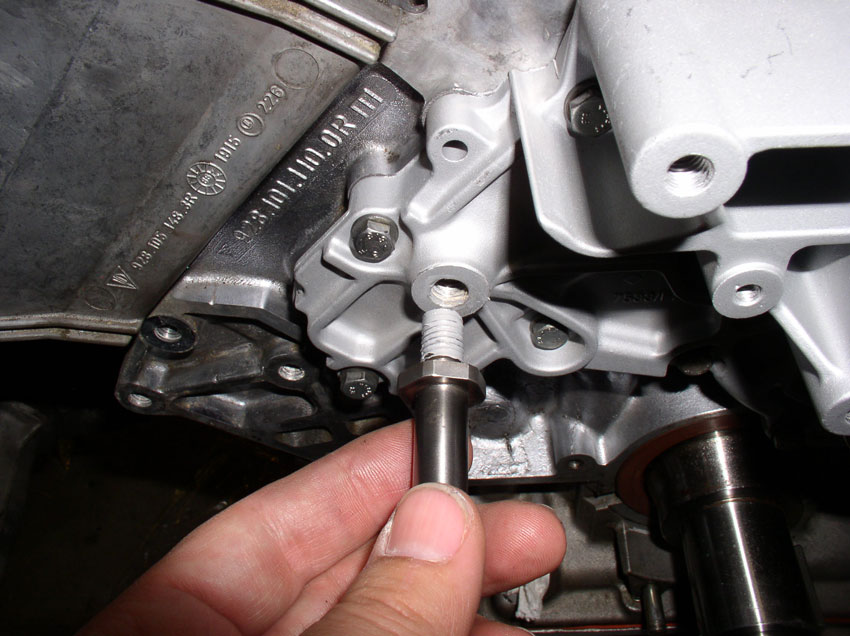
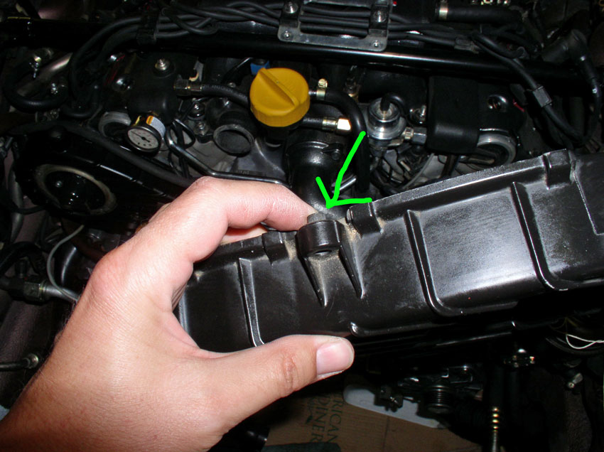
There is one bolt, the 14th bolt, that needs to be left out of the water pump casting. It is highlighted/circled in the picture below. This bolt comes through the center timing belt cover and through the water pump. It will be installed later when we install the cover.
After I have hand tightened all the bolts, I go back and torque all 13 bolts down to the specified torque - 10 Nm or 7 Ftlbs (84 Inchpunds).
Next we install the timing belt tensioner.
Continued.....
In addition, you will need to clean the timing belt tensioner gasket off the block as well as we will be installing the tensioner in the next section.
After the block surface has been cleaned, install the new water pump gasket. I have installed gaskets both dry and with water pump gasket sealant. Both methods seem to work well. I would only recommend sealant (applied to the block surface and the water pump surface) if you have damaged surface areas that would cause a leak. The WSM does not recommend sealant so I usually install the gaskets dry and have had good luck.
There are cutouts in the gasket that match up with the locating pins on the block (highlighted in the pic below). This makes it handy to hold the gasket in place while you install the pump.
Install the pump next and press it into place over the locating pins. The pins should hold the pump in place while you insert and hand tighten the water pump bolts. This procedure will vary slightly depending on whether you have a rebuilt water pump or a brand new water pump to install. Pictured below is a brand new water pump.
If you purchased a rebuilt water pump, you will most likely need to transfer the red plastic timing marker and the tensioner pulley spindle (indicated by the top two arrows in the pic below) from your old water pump to the newly rebuilt water pump. If you purchased a new water pump, both of these items should come already installed on the water pump. As mentioned previously, there are 13 water pump bolts that need to be installed at this time. Eight (8) are long and five (5) are short. The shorter bolts fit in the recessed areas of the pump housing.
The picture below shows a rebuilt water pump being installed and you would install the red timing marker as depicted below. Also highlighted are 2 of the 5 recessed areas for the water pump bolts. There are two of these on the right side of the water pump pulley (as shown below) and the other 3 are on the left side of the water pump pulley.
Again, with the rebuilt pump, you will need to transfer the timing belt tensioner pulley spindle to the newly rebuilt pump. You will need to coat the threads with water pump gasket sealant as shown below. The sealant is available at most auto parts stores. You need to coat the threads before installing the spindle since the spindle threads go all the way through the water pump and you will have a coolant leak without coating these threads.
Tighten the spindle down with a 19mm wrench. If you purchased a new water pump with the spindle already installed, this step is not necessary.
If you purchased a new water pump (as pictured below), you will simply bolt the pump on. In either case (new or rebuilt), hand tighten all 13 bolts. I hand tightened using the 10mm socket and extension bar only.
There is one bolt, the 14th bolt, that needs to be left out of the water pump casting. It is highlighted/circled in the picture below. This bolt comes through the center timing belt cover and through the water pump. It will be installed later when we install the cover.
After I have hand tightened all the bolts, I go back and torque all 13 bolts down to the specified torque - 10 Nm or 7 Ftlbs (84 Inchpunds).
Next we install the timing belt tensioner.
Continued.....
01-02-2010, 01:18 PM
#33
Race Car
This is terrific.
I think you should assemble your write ups on Cd or DVD and perhaps hard copy formatt, and eithep them on EBay for yourself or else provide to the OC to see if they can retail & generate a bit of $ flow. Great service, thanks for your efforts!
I think you should assemble your write ups on Cd or DVD and perhaps hard copy formatt, and eithep them on EBay for yourself or else provide to the OC to see if they can retail & generate a bit of $ flow. Great service, thanks for your efforts!
01-02-2010, 01:25 PM
#34
Addict
Rennlist Member
Rennlist Member
Dwayne...this is the best yet. Assemble all your how-tos into a book and sell them. CDs get ripped off. Work something out with local copy shop for print on demand.
01-02-2010, 02:07 PM
#35
Three Wheelin'
Thread Starter
Join Date: Sep 2007
Location: Ridgecrest, California
Posts: 1,363
Likes: 0
Received 147 Likes
on
31 Posts
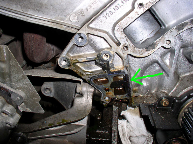
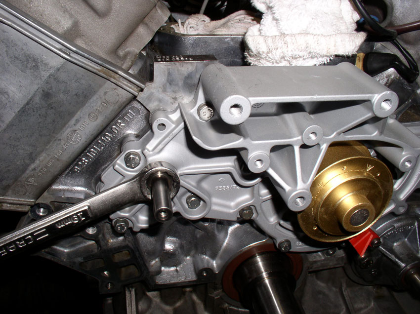
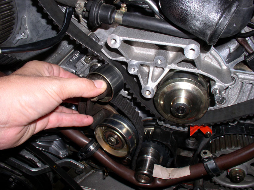
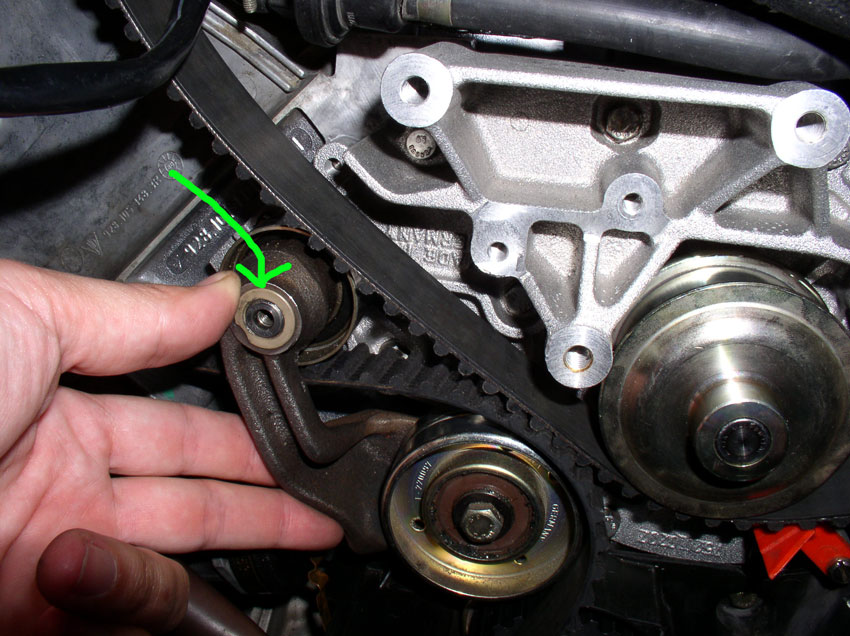
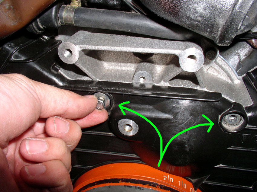
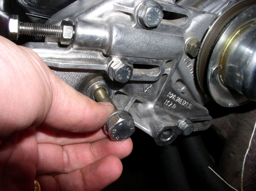
To install the timing belt tensioner, you'll need the 3 bolts that secure the tensioner to the block. You will install the bolts in the holes indicated by the green arrows in the pic below. The longer bolt is used on the bottom hole as the tensioner casting is raised and requires the longer bolt. The 4th hole in the tensioner bracket at the top is reserved for the 13mm bolt that secures the center timing belt cover which will be installed later.
Place the gasket over the tensioner as shown in the pic below. You can insert a couple of the bolts to hold the gasket in place while you position the tensioner on the block. I have installed the tensioner gasket both with sealant and dry. The WSM does not recommend sealant since the gasket is now available (Loctite 574 was recommended by the WSM previously for metal to metal mating of the tensioner to the block with no gasket). It's a matter of personal preference if sealant + gasket is desired. If you use a sealant with the gasket, ensure it is a high temperature sealant. I prefer to install the gasket dry.
This step is optional. I seem to remember reading that a sealant such as Loctite 574 is recommended on the threads of this bolt pointed at in the pic below. I believe it's because this particular bolt goes through to an oil passage. Unfortunately, I can't find the reference that states the sealant is recommended. Therefore, I would say it's optional for now. I'll continue to look for the reference.
When finished installing the bolts, torque each of them down to 20 Nm or 15 Ftlbs.
Installing the timing belt tensioner pulley is next...
Continued....
01-02-2010, 02:14 PM
#36
Rennlist Member
Dwayne-
I'd be willing to print and bind (spiral bind or three ring bind) these for you at cost plus a small profit to make it worth my time. If you'd send me the pdf files, I could assemble them into a binder format, put together a table of contents and then print them on demand as you need them.
I think three ring bind would work well for users because they could buy a manual with just the sections they want and then add to it by purchasing other sections at a later date. The pages could be put in sheet protectors so they could be taken out into the shop without ruining the pages. send me a PM if you are interested.
It wouldn't be free but sure seems like it might be something people would be willing to pay a little bit for.
01-02-2010, 02:43 PM
#37
Three Wheelin'
Thread Starter
Join Date: Sep 2007
Location: Ridgecrest, California
Posts: 1,363
Likes: 0
Received 147 Likes
on
31 Posts
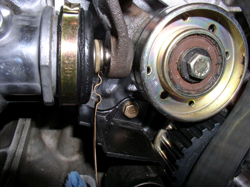
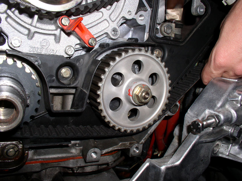
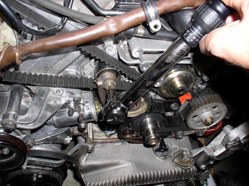
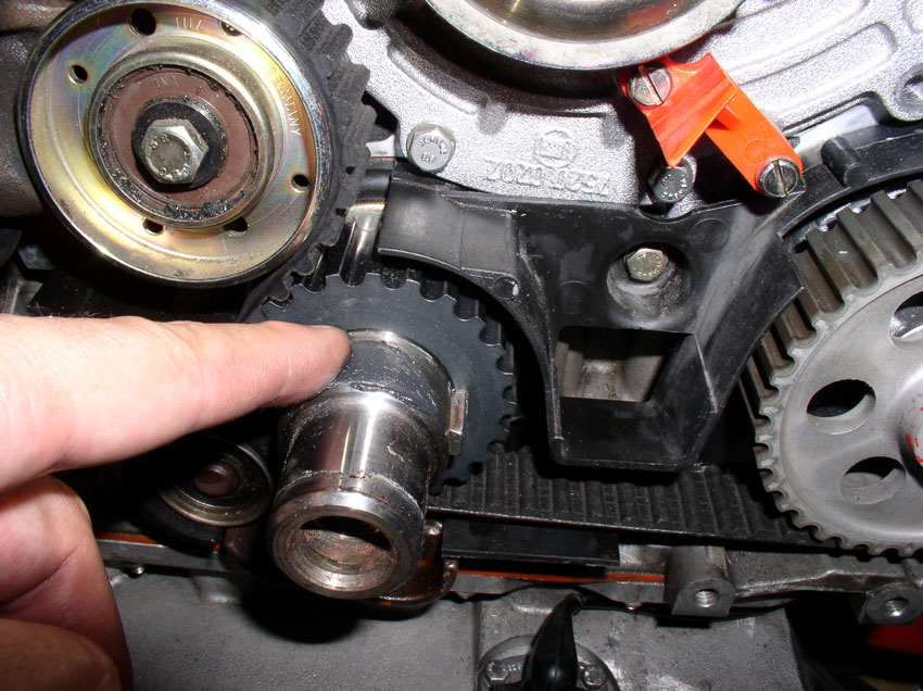
In order to install the Timing Belt Tensioner Pulley, you will need to partially install the new timing belt. First, feed the two loose ends of the two engine wiring harnesses through the timing belt. Then route the timing belt around the timing belt gear on the crankshaft, around the oil pump gear and up and over the driver's side cam gear and under the water pump pulley. Do not pull it tight - we'll do that in the next Chapter. Also, do not wrap timing belt around the passenger side cam gear - you will need the extra slack. This is mainly to keep the timing belt out of the way yet somewhat in place and slack in order to install the tensioner pulley. Before installing the tensioner pulley on the spindle located on the water pump, I applied some synthetic grease to the spindle to ease installation and future removal - see pic below.

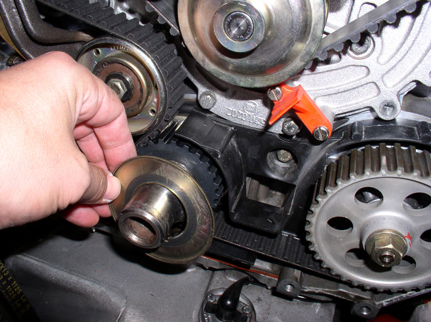
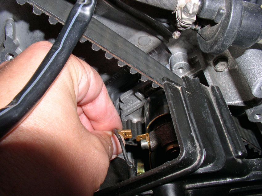
Install the Timing Belt Tension Warning Contact on the end of the tensioner boot fitting as shown below.

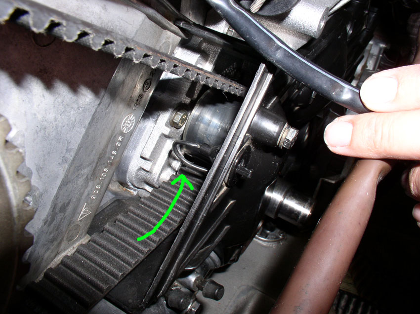
Next, position the tensioner pulley assembly as pictured below. Begin to slide the idler pulley (top pulley) over the freshly geased spindle.
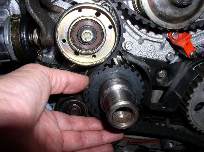
Press the idler pulley on to the spindle until it is fully seated as shown below. Also note how the timing belt is routed in the pic. We'll install the allen head bolt later after we've installed and tightened the belt and we're sure we don't need to take the belt off again.
Finally, ensure the Belt Tension Warning Contact fits into the Tensioner Pulley arm as shown below.
Now we'll route the timing belt and set the initial tension....
Continued....
Install the Timing Belt Tension Warning Contact on the end of the tensioner boot fitting as shown below.
Next, position the tensioner pulley assembly as pictured below. Begin to slide the idler pulley (top pulley) over the freshly geased spindle.
Press the idler pulley on to the spindle until it is fully seated as shown below. Also note how the timing belt is routed in the pic. We'll install the allen head bolt later after we've installed and tightened the belt and we're sure we don't need to take the belt off again.
Finally, ensure the Belt Tension Warning Contact fits into the Tensioner Pulley arm as shown below.
Now we'll route the timing belt and set the initial tension....
Continued....
Last edited by Dwayne; 01-02-2010 at 02:59 PM.
01-02-2010, 03:54 PM
#38
Three Wheelin'
Thread Starter
Join Date: Sep 2007
Location: Ridgecrest, California
Posts: 1,363
Likes: 0
Received 147 Likes
on
31 Posts
Before routing the timing belt, ensure the tension adjustment bolt at the back of the timing belt tensioner is out as far as possible to allow maximum slack in the belt while intalling. Start the installation by routing the timing belt around the crankshaft gear as shown.
Pull the timing belt tight as you route the belt around the oil pump gear next as shown.
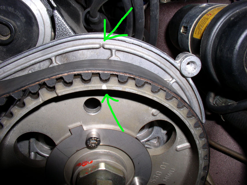
Continue pulling the timing belt tight as you route the timing belt over the driver's side cam gear. Ensure the white mark on the cam gear lines up with the "V" notch in the cam gear backplate as shown. If they are not liined up, you will need to move the cam gear so the paint mark lines up with the notch. This is depicted after the next couple of steps on the passenger side cam gear.
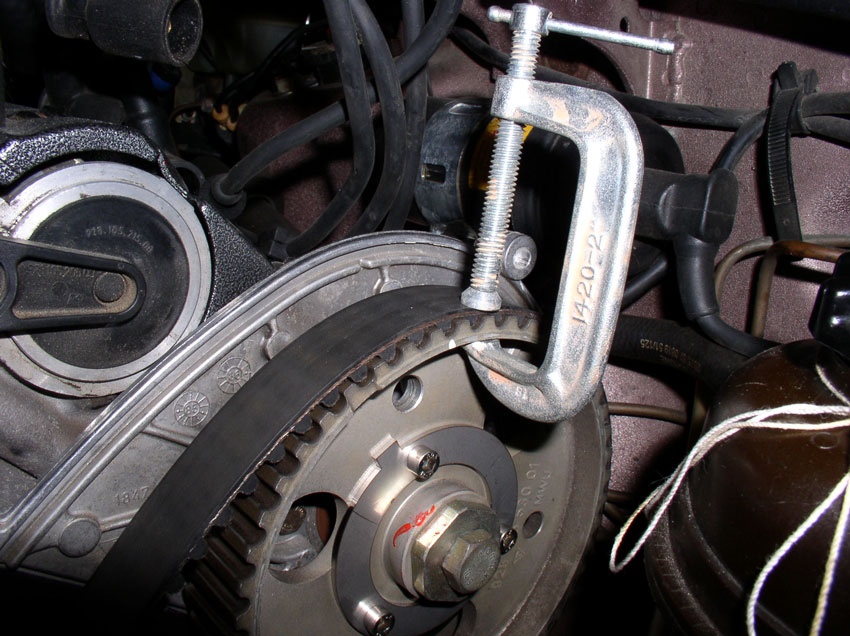
Once the belt is installed on the driver's side cam gear, you can (optionally) hold the belt in place using a small "C" clamp.
Route the timing belt under the water pump pulley, keeping the belt tight.
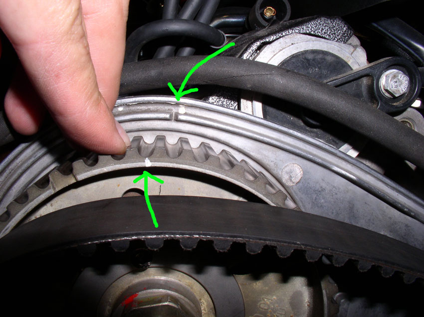
Route the timing belt over the passenger side cam gear next. However, my cam gear was not lined up with the "V" notch as you can see in the pic below. It had "backslid" about one cam gear tooth width.
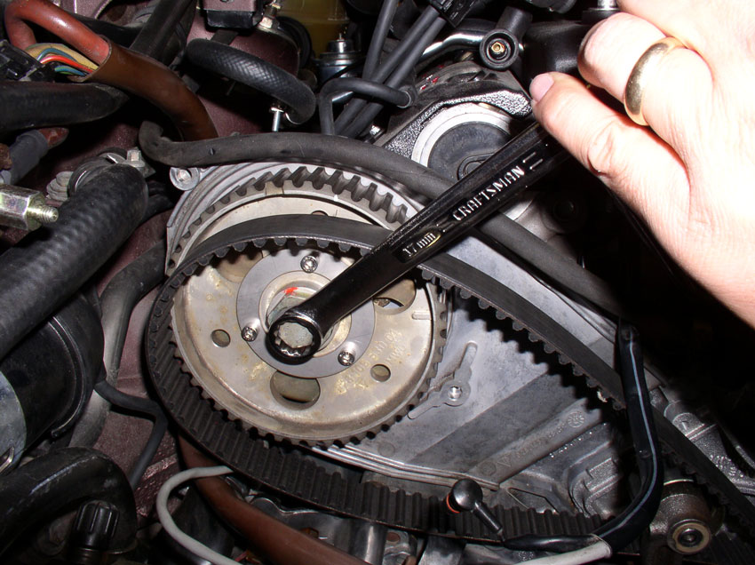
To line up the cam gear, use a 17mm long handled wrench to turn the cam gear as shown in the picture below. Only turn the cam gear in the clockwise direction. If the white mark is past the "V" notch in the backplate, you will need to rotate the cam gear all the way around clockwise again to line up the paint mark with the "V" notch.
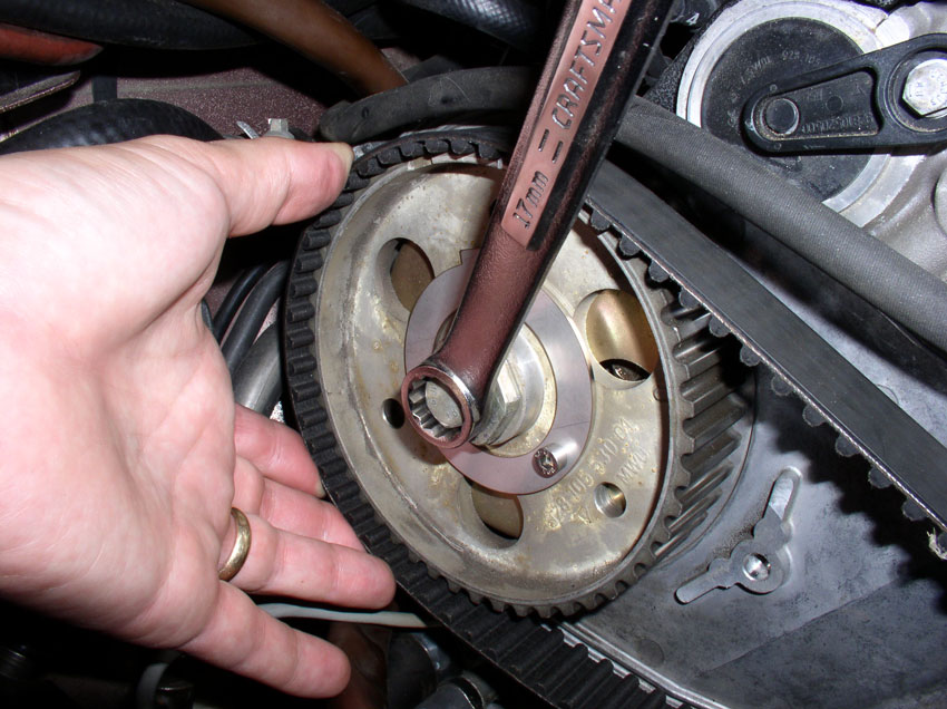
Once the paint mark is lined up with the "V" notch, hold the cam gear in place with the wrench while you pull the timing belt tight and slide it onto the gear with the other hand as shown.
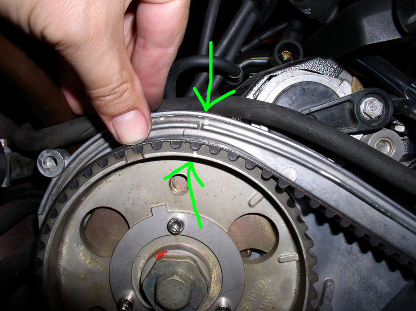
When the belt is correctly positioned on the cam gear, the paint mark should line up with the "V" notch as shown below.
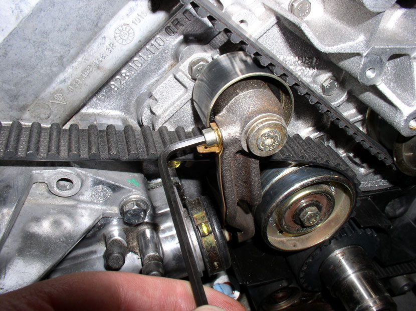
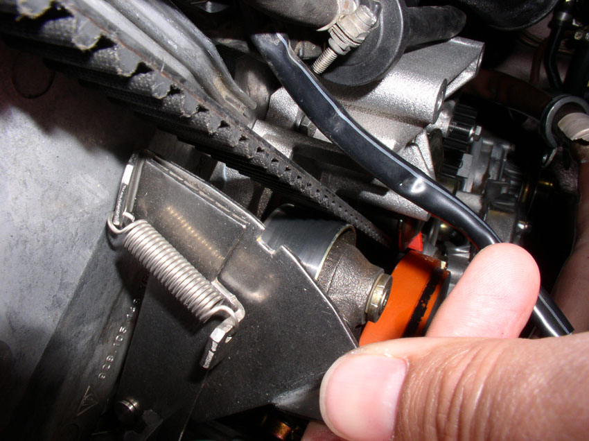
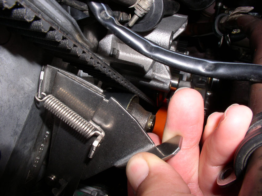
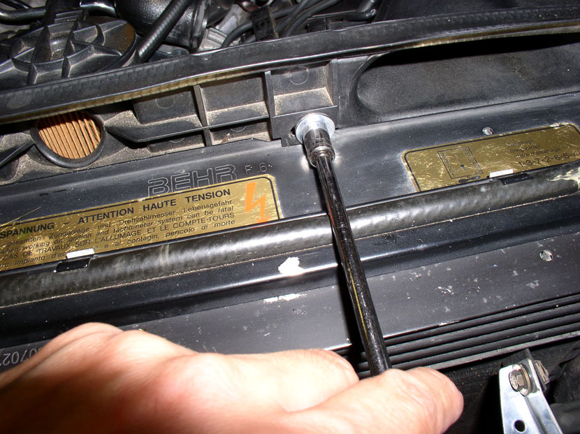
If everything looks "normal" at this point, we need to tighten the tensioner pulley bolt. Install the 4mm allen head bolt and washer into the pulley spindle as shown.
Then torque to no more than 10 Nm or 7 Ftlbs making sure the allen socket is fully seated in the bolt head to minimize chances of striping the bolt.
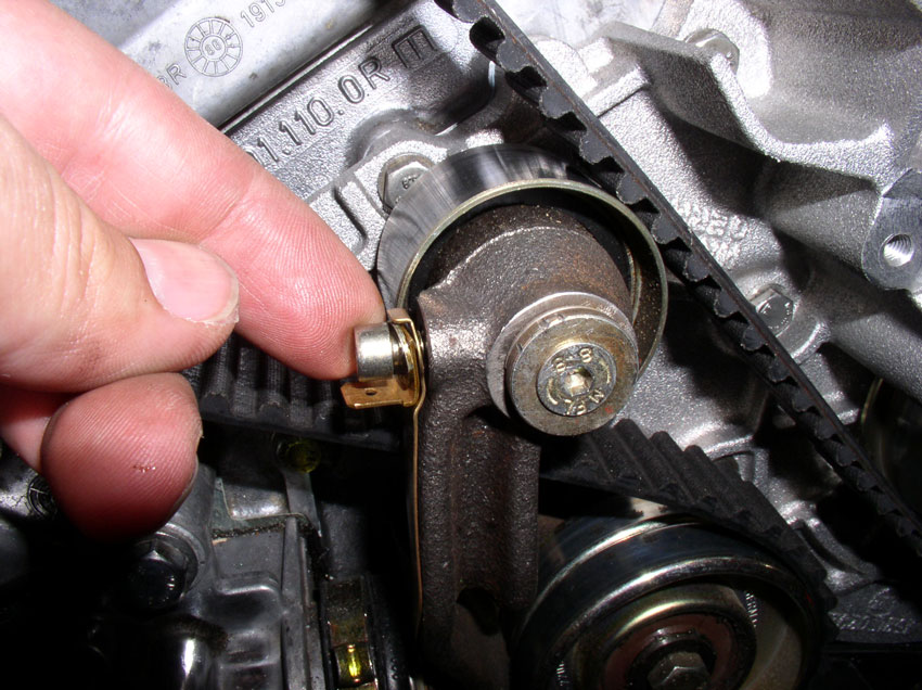
Next, attach the tension warning contact stip to the tensioner knuckle using the 4mm allen head bolt as shown. Note how the electrical connector blade is oriented. Make sure it is not oriented facing the front of the car as it may interfere with the timing belt cover when the electrical lead is connected to it.
Then snug down the allen head bolt with a wrench or socket. I did not feel the need to torque this bolt down as it seems smaller than an M6.
Now tigten the tming belt tensioner adjustment bolt using a 17mm wrench. Turn the bolt in a clockwise direction until all the slack is taken out of the timing belt and the timing belt is snug around the tensioner pulley.
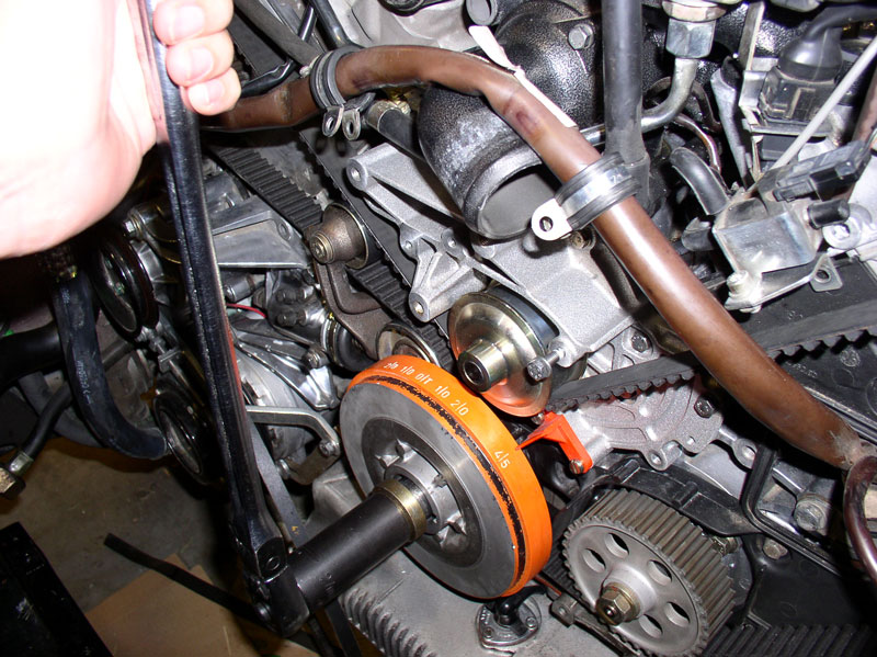
Next, we'll check the initial tension but we have to rotate the engine to the TDC position in order to get an accurate tension reading. To prepare for rotating the engine, we'll install the vibration dampener on the crankshaft. First, I applied a thin layer of synthetic grease to the end of the crankshaft to ease the installation and future removal of the vibration dampener.
Continued.....
Pull the timing belt tight as you route the belt around the oil pump gear next as shown.
Continue pulling the timing belt tight as you route the timing belt over the driver's side cam gear. Ensure the white mark on the cam gear lines up with the "V" notch in the cam gear backplate as shown. If they are not liined up, you will need to move the cam gear so the paint mark lines up with the notch. This is depicted after the next couple of steps on the passenger side cam gear.
Once the belt is installed on the driver's side cam gear, you can (optionally) hold the belt in place using a small "C" clamp.
Route the timing belt under the water pump pulley, keeping the belt tight.
Route the timing belt over the passenger side cam gear next. However, my cam gear was not lined up with the "V" notch as you can see in the pic below. It had "backslid" about one cam gear tooth width.
To line up the cam gear, use a 17mm long handled wrench to turn the cam gear as shown in the picture below. Only turn the cam gear in the clockwise direction. If the white mark is past the "V" notch in the backplate, you will need to rotate the cam gear all the way around clockwise again to line up the paint mark with the "V" notch.
Once the paint mark is lined up with the "V" notch, hold the cam gear in place with the wrench while you pull the timing belt tight and slide it onto the gear with the other hand as shown.
When the belt is correctly positioned on the cam gear, the paint mark should line up with the "V" notch as shown below.
If everything looks "normal" at this point, we need to tighten the tensioner pulley bolt. Install the 4mm allen head bolt and washer into the pulley spindle as shown.
Then torque to no more than 10 Nm or 7 Ftlbs making sure the allen socket is fully seated in the bolt head to minimize chances of striping the bolt.
Next, attach the tension warning contact stip to the tensioner knuckle using the 4mm allen head bolt as shown. Note how the electrical connector blade is oriented. Make sure it is not oriented facing the front of the car as it may interfere with the timing belt cover when the electrical lead is connected to it.
Then snug down the allen head bolt with a wrench or socket. I did not feel the need to torque this bolt down as it seems smaller than an M6.
Now tigten the tming belt tensioner adjustment bolt using a 17mm wrench. Turn the bolt in a clockwise direction until all the slack is taken out of the timing belt and the timing belt is snug around the tensioner pulley.
Next, we'll check the initial tension but we have to rotate the engine to the TDC position in order to get an accurate tension reading. To prepare for rotating the engine, we'll install the vibration dampener on the crankshaft. First, I applied a thin layer of synthetic grease to the end of the crankshaft to ease the installation and future removal of the vibration dampener.
Continued.....
01-02-2010, 04:12 PM
#39
Three Wheelin'
Thread Starter
Join Date: Sep 2007
Location: Ridgecrest, California
Posts: 1,363
Likes: 0
Received 147 Likes
on
31 Posts
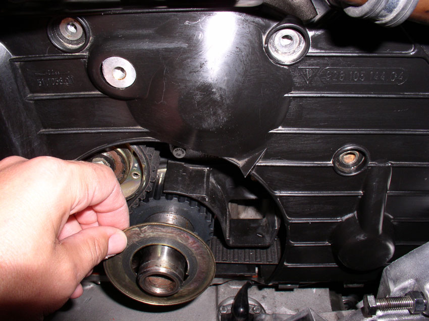
Next, install the timing belt guide onto the crankshaft as shown.
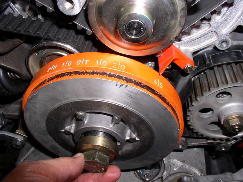
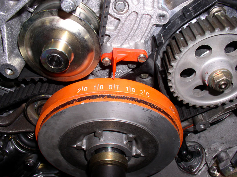
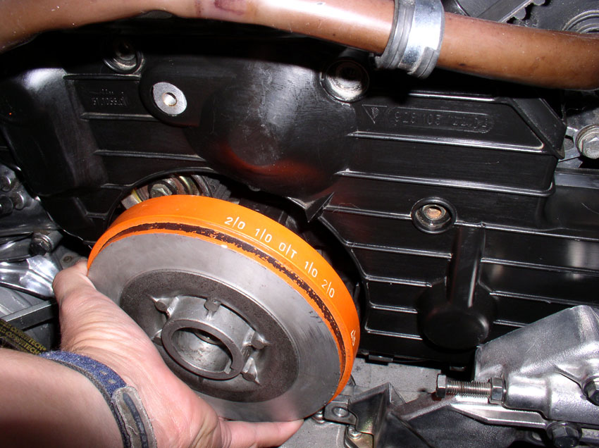
Install the vibration dampener onto the crankshaft as shown. The "45" mark should line up with the red timing indicator as shown below.
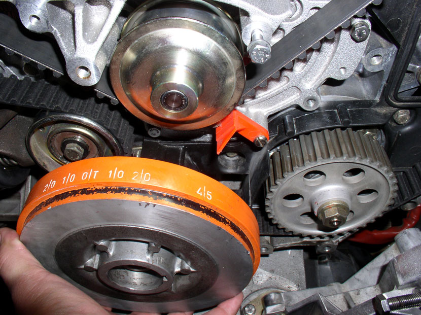
Install the 27mm crankshaft bolt and washer.
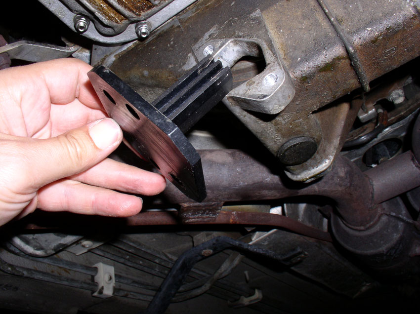
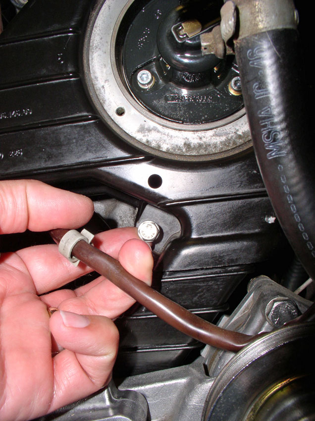
From underneath the car, remove the flywheel lock tool.
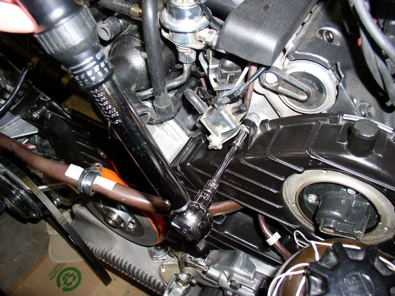
Using a 27mm socket and long handle socket wrench, turn the crankshaft clockwise at least two revolutions....
...until you come to the "OT" mark on the dampener indicating Top Dead Center (TDC). Verify you are at TDC by inspecting the cut "V" notches in the cam gears line up with the cut "V" notches in the cam gear backplates for both cam gears.
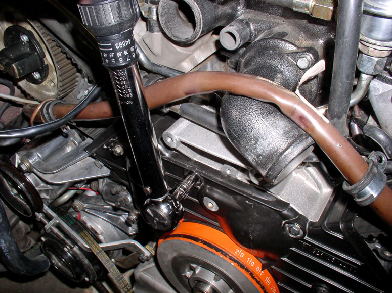
Once at TDC, I checked the belt tension with the Kempf tool. As you can see, it was too loose.
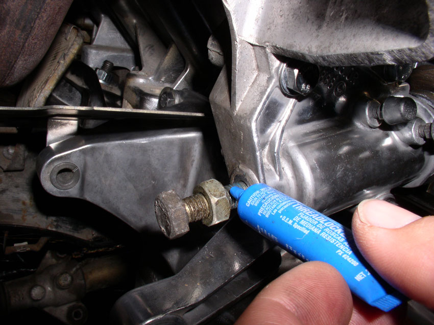
Before the final tightening, you can (optionally) apply some thread locker Blue to the threads of the tension adjustment bolt.
Then tighten the adjustment bolt again clockwise (I tightened it about 2 revolutions) and repeat the process of rotating the crank two revolutions to TDC again and check the tension. Repeat this process until.....
The tension is properly set according to the tool as seen below (i.e., the indicator is in the middle of the notch on the tool). When the tension is correct, tighten the locking nut (17mm) on the tensioner adjusting bolt (back of the tensioner).
Continued....
Install the vibration dampener onto the crankshaft as shown. The "45" mark should line up with the red timing indicator as shown below.
Install the 27mm crankshaft bolt and washer.
From underneath the car, remove the flywheel lock tool.
Using a 27mm socket and long handle socket wrench, turn the crankshaft clockwise at least two revolutions....
...until you come to the "OT" mark on the dampener indicating Top Dead Center (TDC). Verify you are at TDC by inspecting the cut "V" notches in the cam gears line up with the cut "V" notches in the cam gear backplates for both cam gears.
Once at TDC, I checked the belt tension with the Kempf tool. As you can see, it was too loose.
Before the final tightening, you can (optionally) apply some thread locker Blue to the threads of the tension adjustment bolt.
Then tighten the adjustment bolt again clockwise (I tightened it about 2 revolutions) and repeat the process of rotating the crank two revolutions to TDC again and check the tension. Repeat this process until.....
The tension is properly set according to the tool as seen below (i.e., the indicator is in the middle of the notch on the tool). When the tension is correct, tighten the locking nut (17mm) on the tensioner adjusting bolt (back of the tensioner).
Continued....
01-02-2010, 05:31 PM
#40
Three Wheelin'
Thread Starter
Join Date: Sep 2007
Location: Ridgecrest, California
Posts: 1,363
Likes: 0
Received 147 Likes
on
31 Posts
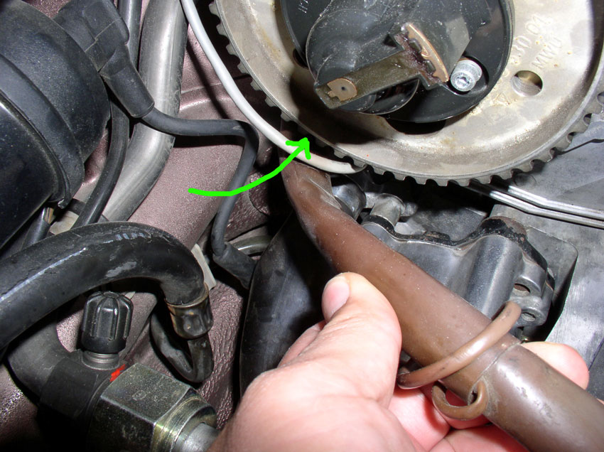
Next, route the engine harnesses that were detached previously back to their respective locations. Starting with the larger harness first, push the end of the 14-pin plug underneath the passenger side cam gear as shown.
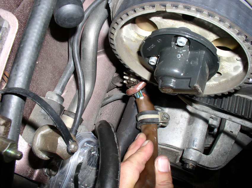
Continue pushing the harness up behind the passenger cam gear until you can grasp it from behind the gear near the engine lift hook.
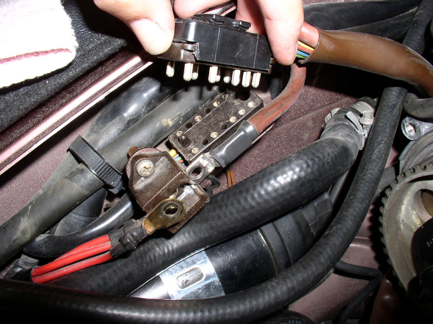
Pull the harness through enough to connect the 14-pin plug to its recepticle next to the battery charging post as pictured.
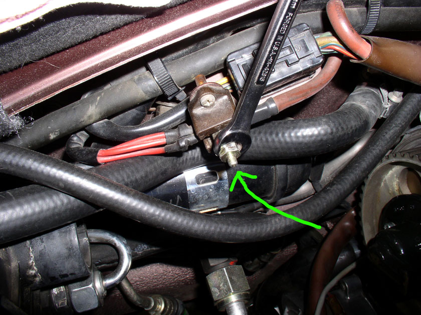
Connect the red power cable to the battery charging post and tighten down the 11mm charging post bolt as shown.
Place the harness in the harness clamp next to the engine lift hook and tighten down the 10mm clamp nut as shown.
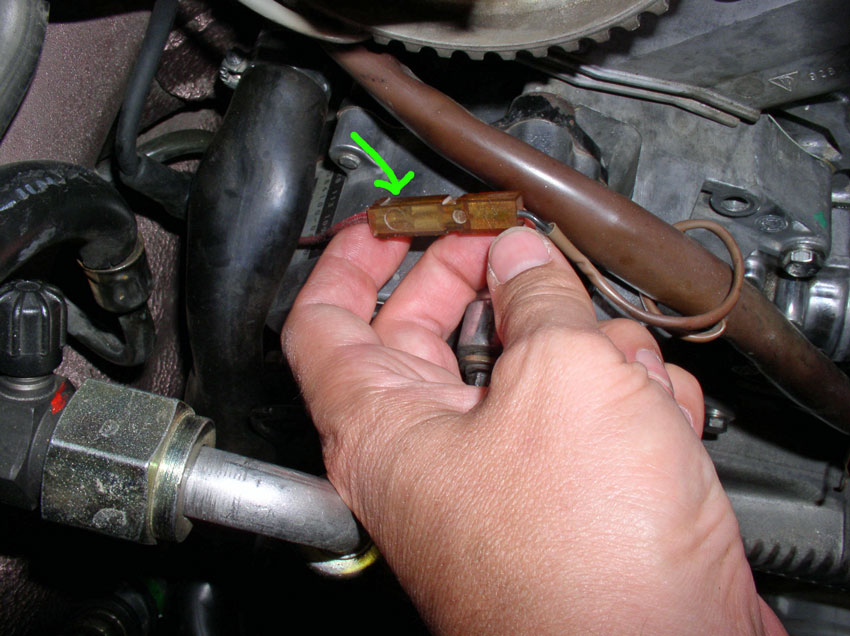
Re-connect the A/C compressor power lead to the harness. The power lead connects to a blade terminal located inside the square plastic connector as shown below.
Next, route the smaller engine harness in behind the power steering fluid hoses and behind the power steering fluid reservoir bracket as shown.
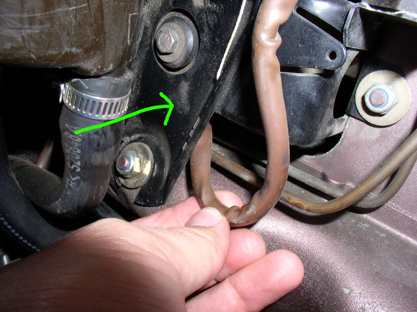
Connect the end to the terminal box as shown and secure the lead by tightening down the phillips screw.
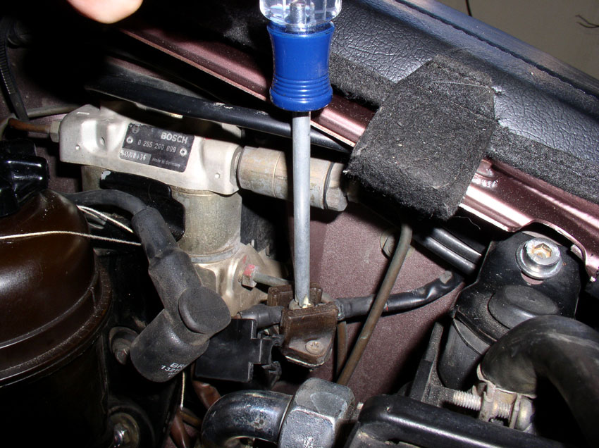
Close the protective cover lid over the connection box.
To prepare for installing the center timing belt cover, I removed the vibration dampener for ease of installation. You can actually install the cover with the dampener in place as well. Do not secure the cover yet.
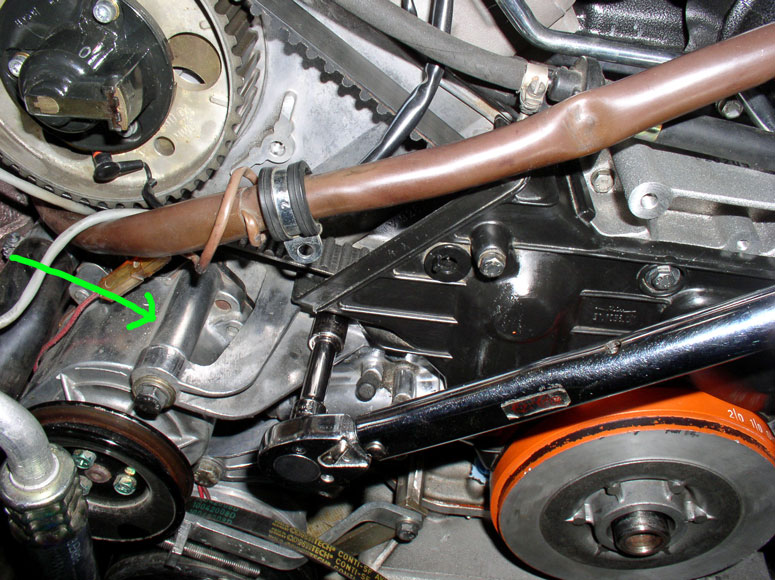
With the cover pulled out a couple of inches, attach the belt tension warning wire to the blade connector attached to the tensioner pulley knuckle as shown below. The blade connector on the pulley knuckle can be oriented down or toward the back as shown in the pic.
Ensure the wire is free from contact with the timing belt or idler pulley as shown.
Since I removed the vibration dampener for the cover install, I needed to re-install the timing belt guide on the crankshaft....
....followed by installing the vibration dampener on the end of the crankshaft next.
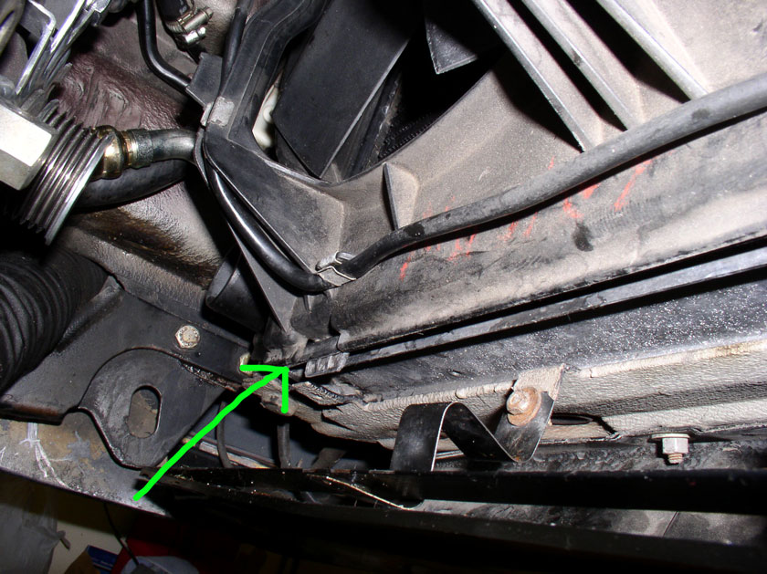
Install the 13mm bolt on the left side of the cover next.
Continued.....
Continue pushing the harness up behind the passenger cam gear until you can grasp it from behind the gear near the engine lift hook.
Pull the harness through enough to connect the 14-pin plug to its recepticle next to the battery charging post as pictured.
Connect the red power cable to the battery charging post and tighten down the 11mm charging post bolt as shown.
Place the harness in the harness clamp next to the engine lift hook and tighten down the 10mm clamp nut as shown.
Re-connect the A/C compressor power lead to the harness. The power lead connects to a blade terminal located inside the square plastic connector as shown below.
Next, route the smaller engine harness in behind the power steering fluid hoses and behind the power steering fluid reservoir bracket as shown.
Connect the end to the terminal box as shown and secure the lead by tightening down the phillips screw.
Close the protective cover lid over the connection box.
To prepare for installing the center timing belt cover, I removed the vibration dampener for ease of installation. You can actually install the cover with the dampener in place as well. Do not secure the cover yet.
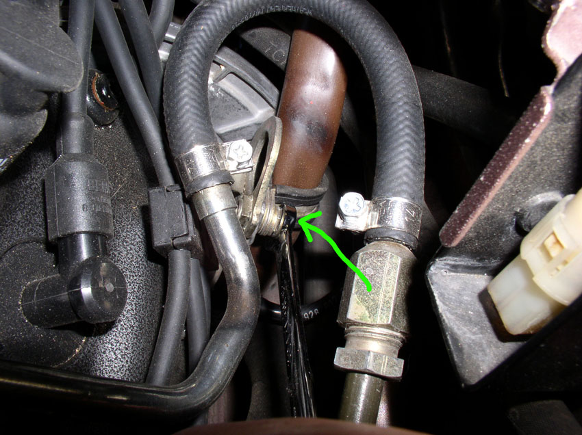
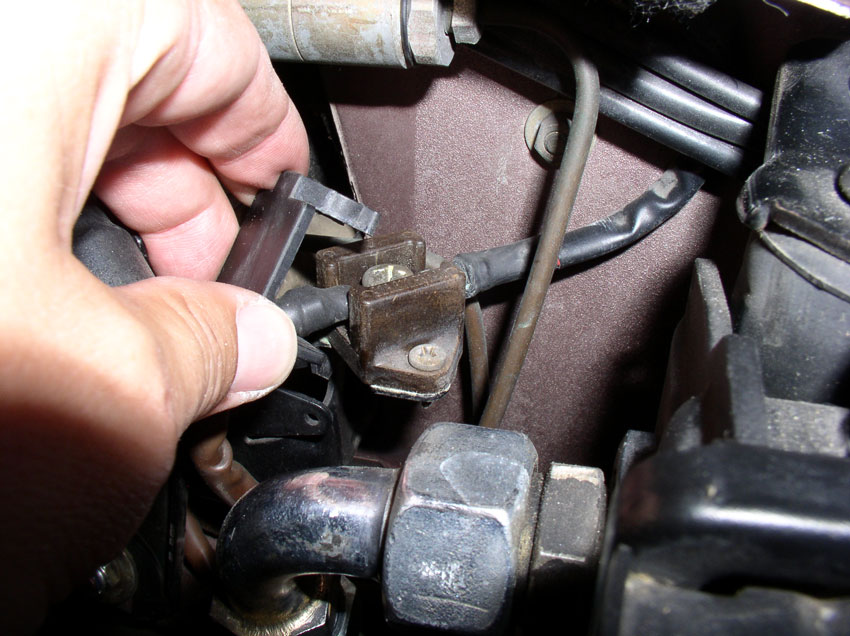
With the cover pulled out a couple of inches, attach the belt tension warning wire to the blade connector attached to the tensioner pulley knuckle as shown below. The blade connector on the pulley knuckle can be oriented down or toward the back as shown in the pic.
Ensure the wire is free from contact with the timing belt or idler pulley as shown.
Since I removed the vibration dampener for the cover install, I needed to re-install the timing belt guide on the crankshaft....
....followed by installing the vibration dampener on the end of the crankshaft next.
Install the 13mm bolt on the left side of the cover next.
Continued.....
01-02-2010, 05:58 PM
#41
Three Wheelin'
Thread Starter
Join Date: Sep 2007
Location: Ridgecrest, California
Posts: 1,363
Likes: 0
Received 147 Likes
on
31 Posts
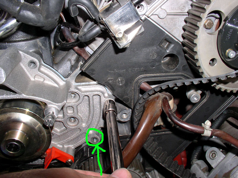
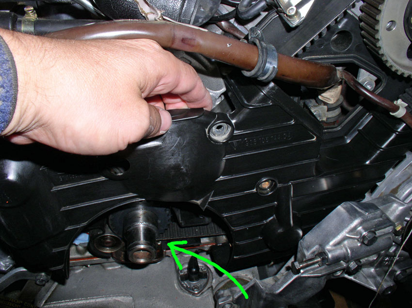
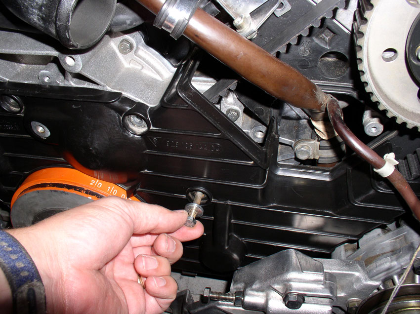
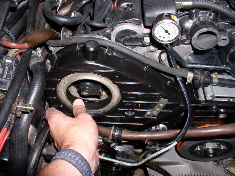
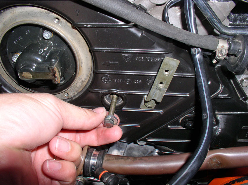
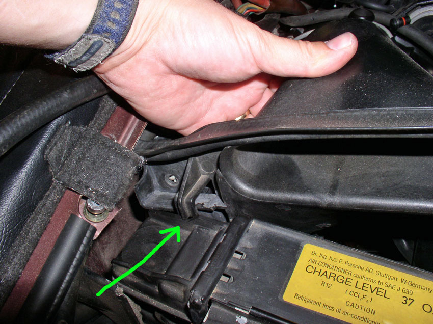
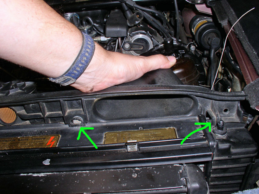
Install and hand-tighten the long 10mm bolt near the center of the cover as shown below. This is the bolt that goes through the water pump casing.
Install and hand-tighten the two 10mm bolts at the top of the cover as indicated by the green arrows below.
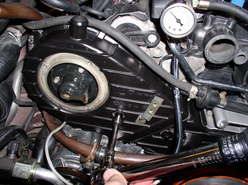
Torque the three 10mm bolts to 10 Nm or 7 Ftlbs.
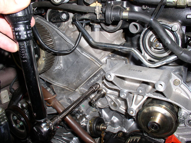
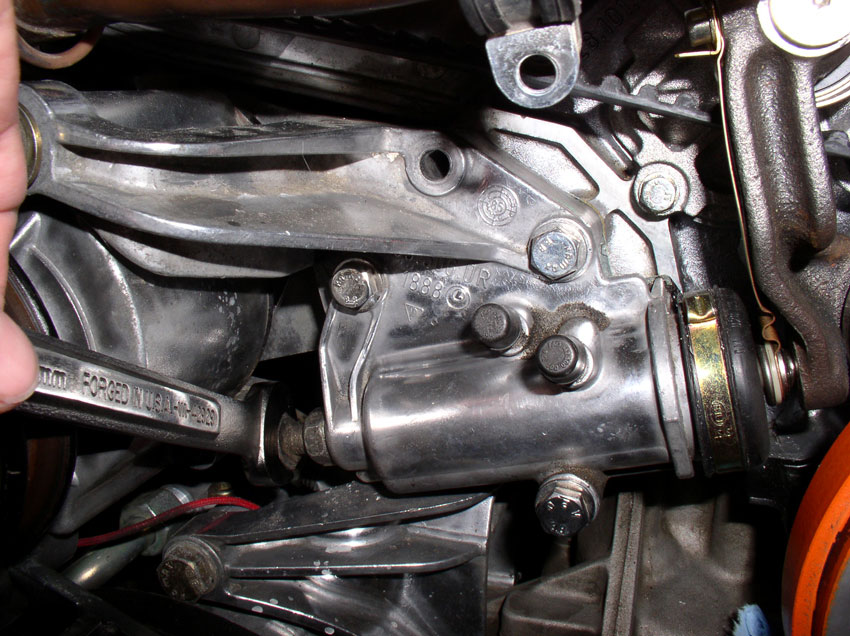
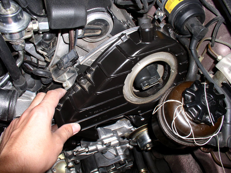
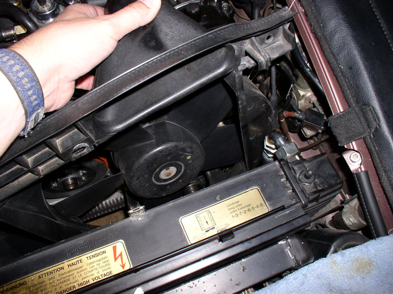
Torque the 13mm bolt on the left side of the cover to 20 Nm or 15 Ftlbs. The center cover is now installed. Next, install the air pump onto the tensioner bracket and insert and hand-tighten the long 13mm pivot bolt as shown in the pic below.
Next, we'll fill the tensioner with oil....
Continued....
Install and hand-tighten the two 10mm bolts at the top of the cover as indicated by the green arrows below.
Torque the three 10mm bolts to 10 Nm or 7 Ftlbs.
Torque the 13mm bolt on the left side of the cover to 20 Nm or 15 Ftlbs. The center cover is now installed. Next, install the air pump onto the tensioner bracket and insert and hand-tighten the long 13mm pivot bolt as shown in the pic below.
Next, we'll fill the tensioner with oil....
Continued....
01-02-2010, 06:17 PM
#42
Three Wheelin'
Thread Starter
Join Date: Sep 2007
Location: Ridgecrest, California
Posts: 1,363
Likes: 0
Received 147 Likes
on
31 Posts
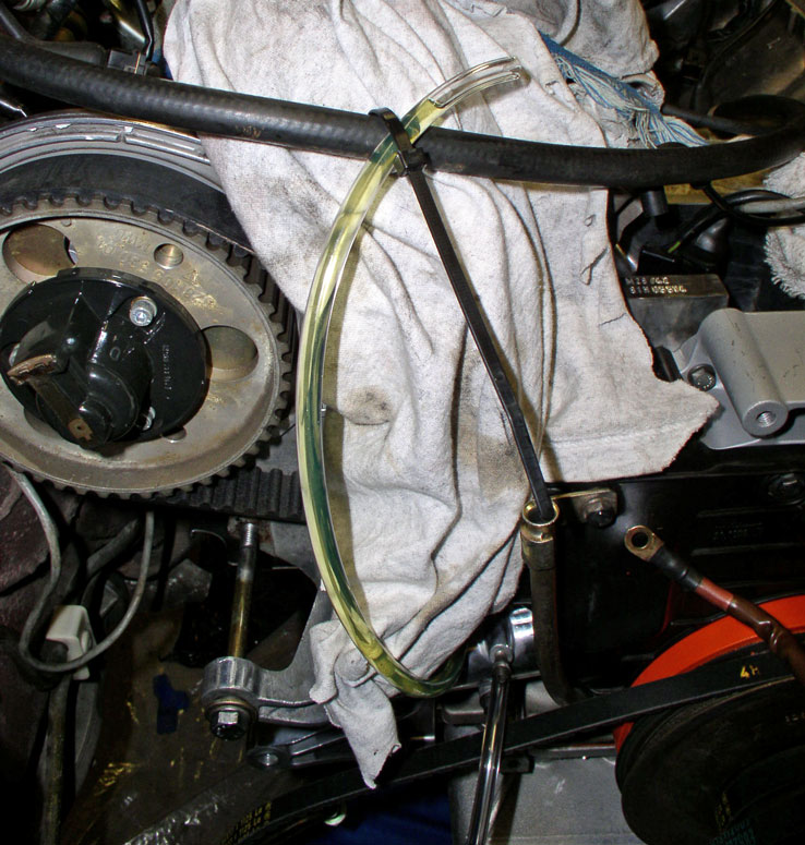
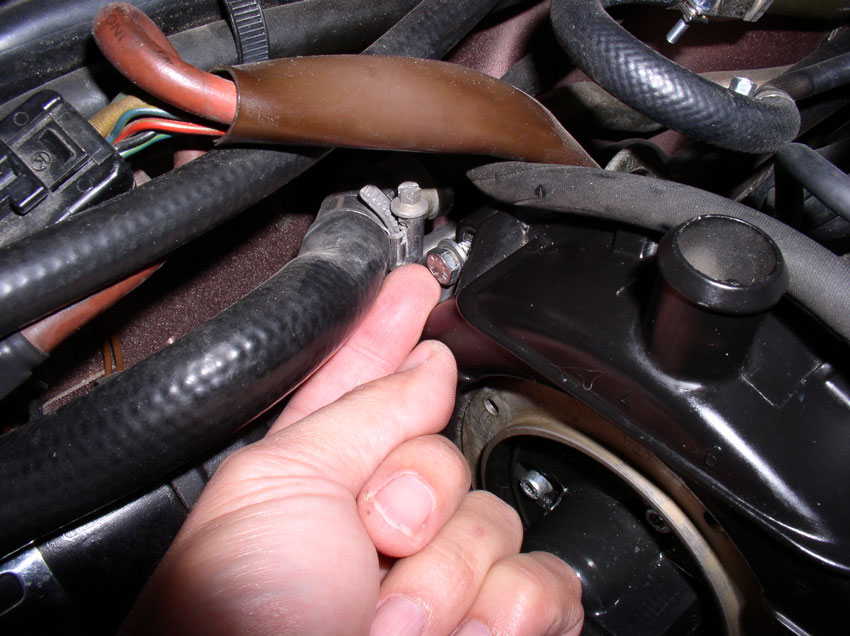
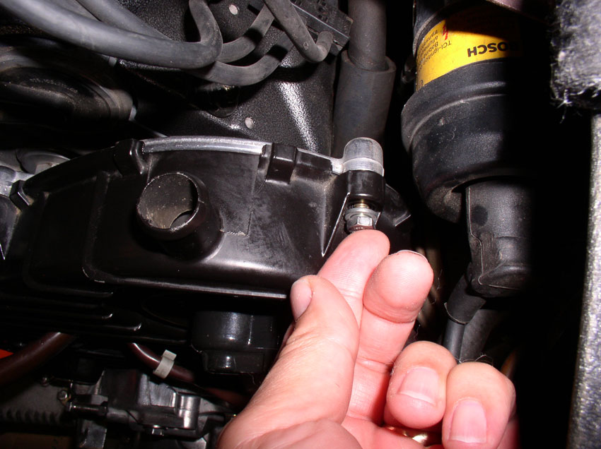
To fill the tensioner, I used 90w gear oil. You can also use motor oil according to the WSM. The main thing is to not force the oil into the tensioner so that it breaks a seal or gasket. For this purpose, I decided to let gravity do the work. I attached 2 long clear plastic tubes that fit snugly over the fill and bleeder fittings on the tensioner as shown in the pic below. Loosen the fittings first before attaching the tubes. The fill port is the port to the left and the bleeder port is the one to the right. Angle the hose to the right downward and into a catch can to catch any fluid that may come out through the bleeder port. The fill tube you can tie with a zip tie to one of the hoses or harnesses near the topside of the engine to keep it in place.
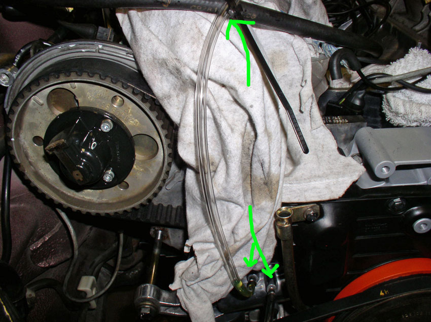
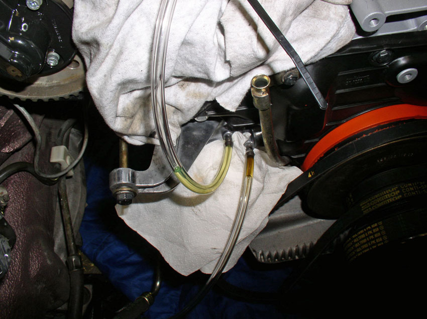
Next, fill the tube on the left that's connected to the fill port with 90w gear oil or clean motor oil. Fill the tube to the top as shown in the picture below. It will take a while for the tensioner to fill with this method so you may leave it unattended and work elsewhere on the car while it is filling. You will be watching to see if any oil comes out the bleeder port as seen through the plastic tube.
You may need to fill the hose 2 or 3 times before you finally see oil coming out the bleeder port as shown in the pic below. The tensioner is full.
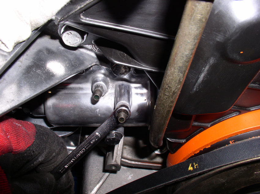
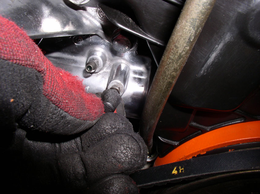
At this point, remove the plastic tubes and tighten down both of the fittings. Only about 3 Ftlbs should do it.
Attach the protective covers next and you're done.
Continued......
Next, fill the tube on the left that's connected to the fill port with 90w gear oil or clean motor oil. Fill the tube to the top as shown in the picture below. It will take a while for the tensioner to fill with this method so you may leave it unattended and work elsewhere on the car while it is filling. You will be watching to see if any oil comes out the bleeder port as seen through the plastic tube.
You may need to fill the hose 2 or 3 times before you finally see oil coming out the bleeder port as shown in the pic below. The tensioner is full.
At this point, remove the plastic tubes and tighten down both of the fittings. Only about 3 Ftlbs should do it.
Attach the protective covers next and you're done.
Continued......
01-02-2010, 06:34 PM
#43
Three Wheelin'
Thread Starter
Join Date: Sep 2007
Location: Ridgecrest, California
Posts: 1,363
Likes: 0
Received 147 Likes
on
31 Posts
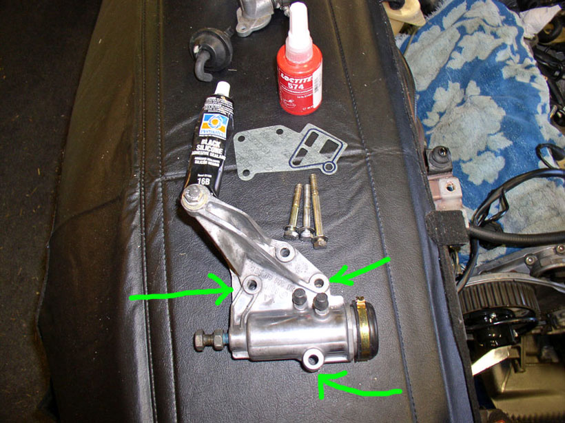
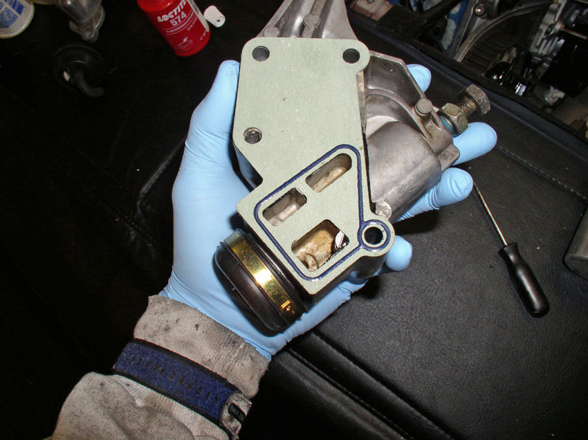
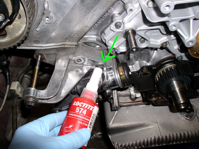
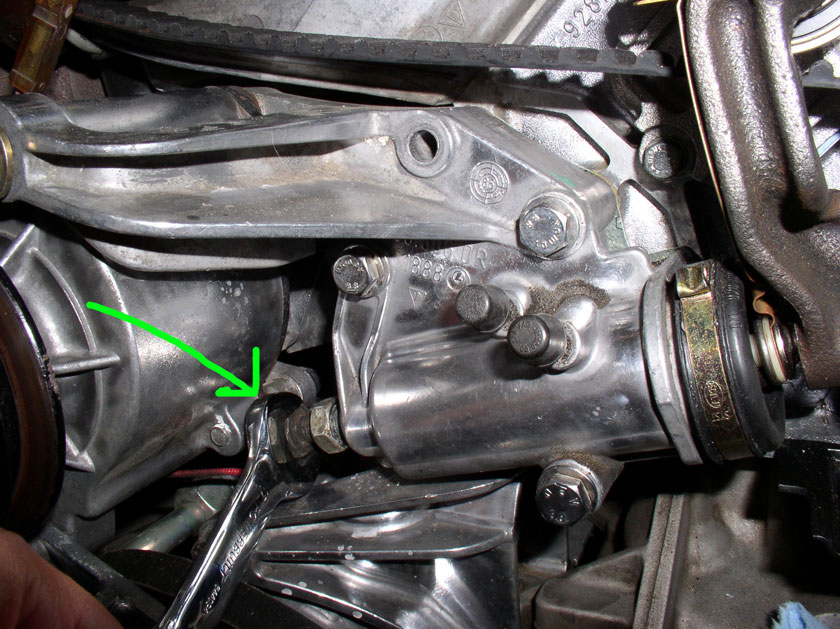
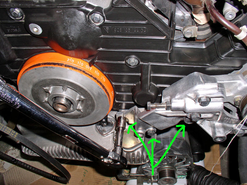
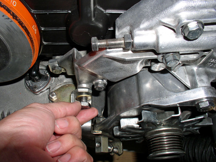
Install the Power Steering pump and bracket next. You will notice there is a locating pin on the engine block shown in the pic below.
The locating pin is mated to this locating hole in the PS bracket. Place the PS bracket on the locating pin and press into place.
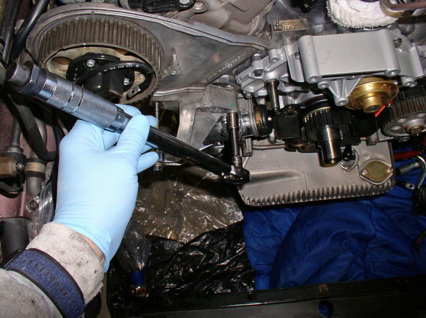
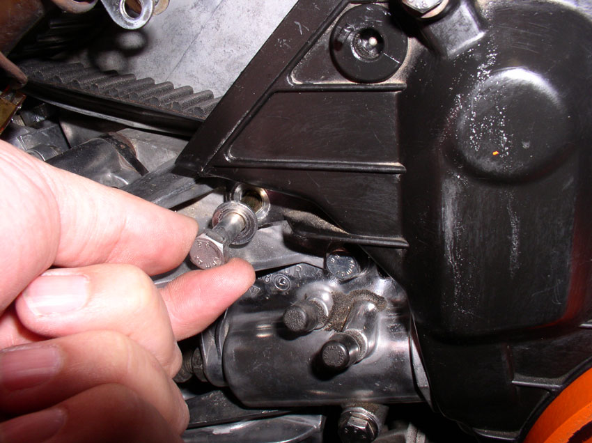
Next, install the 17mm bolt as shown below and hand tighten.
Install the two 13mm bolts and hand tighten as shown.
The bracket can now be torqued down. You will torque the 3 bolts just installed and indicated by the green arrows below. The two 13mm bolts to the left are torqued to 20 Nm or 15 Ftlbs. The 17mm bolt is torqued to 40 Nm or 30 Ftlbs.
Next, bring up the alternator and insert it onto the bracket....
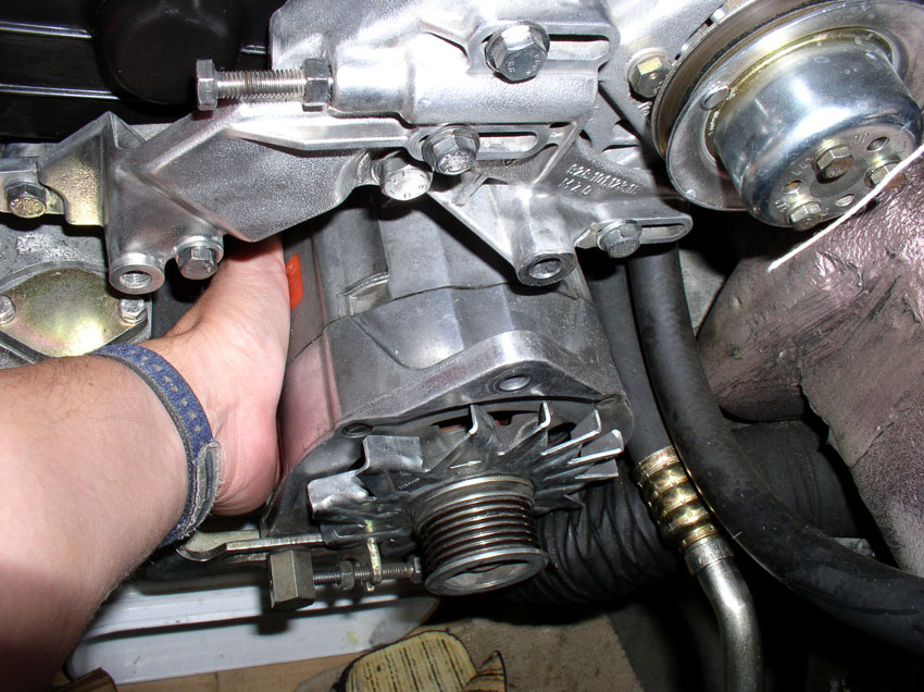
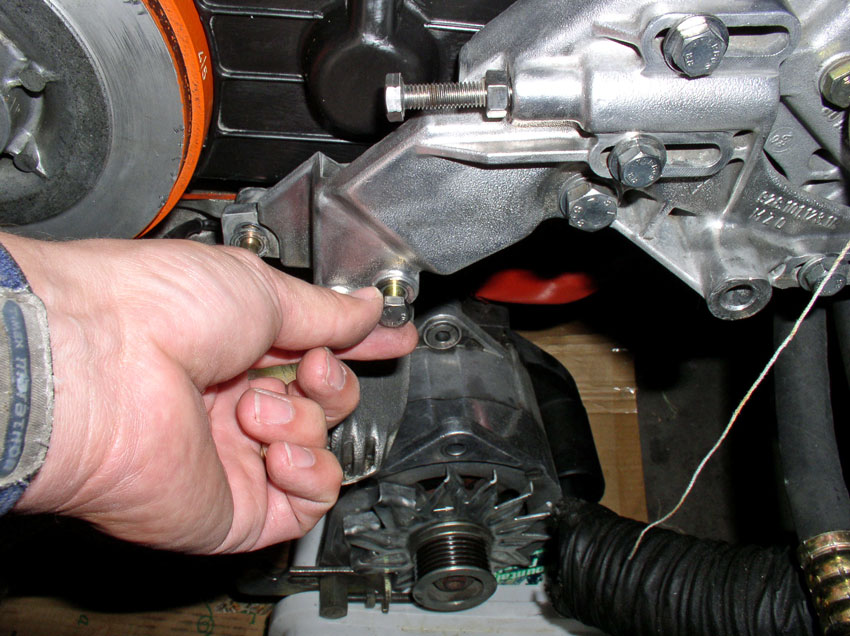
...and use the long 17mm pivot bolt to help locate the alternator on the bracket. Hand tighten the pivot bolt.
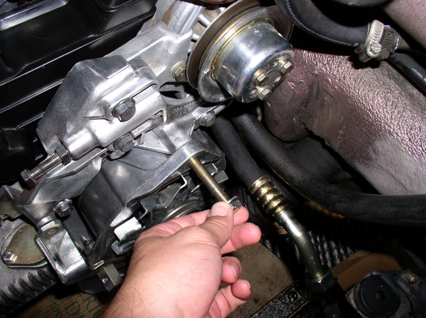
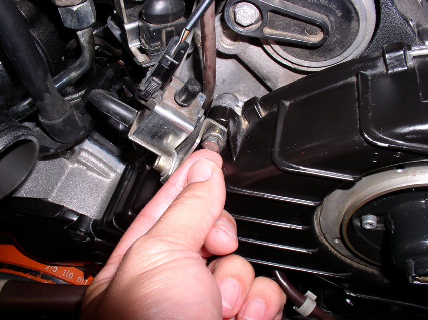
Bring the tension adjusting bracket up and install it with the 17mm bolt as shown below. Hand-tighten the bolt at this point. This bolt will be torqued down after the belt is installed and tensioned.
Next, we will install the upper cam covers....
Continued....
The locating pin is mated to this locating hole in the PS bracket. Place the PS bracket on the locating pin and press into place.
Next, install the 17mm bolt as shown below and hand tighten.
Install the two 13mm bolts and hand tighten as shown.
The bracket can now be torqued down. You will torque the 3 bolts just installed and indicated by the green arrows below. The two 13mm bolts to the left are torqued to 20 Nm or 15 Ftlbs. The 17mm bolt is torqued to 40 Nm or 30 Ftlbs.
Next, bring up the alternator and insert it onto the bracket....
...and use the long 17mm pivot bolt to help locate the alternator on the bracket. Hand tighten the pivot bolt.
Bring the tension adjusting bracket up and install it with the 17mm bolt as shown below. Hand-tighten the bolt at this point. This bolt will be torqued down after the belt is installed and tensioned.
Next, we will install the upper cam covers....
Continued....
01-02-2010, 06:49 PM
#44
Three Wheelin'
Thread Starter
Join Date: Sep 2007
Location: Ridgecrest, California
Posts: 1,363
Likes: 0
Received 147 Likes
on
31 Posts
I started with install the passenger side upper cam cover. Place it into position.
You will notice a locating pin on the upper bolt. The cam cover also has a lip that fits over the cam gear back plate. Make sure the lip is over the back plate and the locating pin should slide into place.

There are 2 bolts that secure the cover in place. Install the long 10mm bolt as shown and hand tighten.
Install the shorter 10mm bolt in the upper part of the cover as shown.
Torque both bolts down to 10 Nm or 7 Ftlbs.
The driver's side cam cover also has a locating pin as shown below and a lip that fits over the cam back plate.
Install the cover ensuring the lip is over the back plate.
This cover has three 10mm bolts that secure the cover. Install the 10mm bolt that also secures the flappy vacuum solenoid bracket as shown below.
Install the 10mm bolt at the top of the cover as shown.
Finally, install the "hidden" 10mm bolt at the cam cover opening as shown.
Torque all three 10mm bolts to 10 Nm or 7 Ftlbs.
Next, we install the fan shroud....
Continued....
You will notice a locating pin on the upper bolt. The cam cover also has a lip that fits over the cam gear back plate. Make sure the lip is over the back plate and the locating pin should slide into place.
There are 2 bolts that secure the cover in place. Install the long 10mm bolt as shown and hand tighten.
Install the shorter 10mm bolt in the upper part of the cover as shown.
Torque both bolts down to 10 Nm or 7 Ftlbs.
The driver's side cam cover also has a locating pin as shown below and a lip that fits over the cam back plate.
Install the cover ensuring the lip is over the back plate.
This cover has three 10mm bolts that secure the cover. Install the 10mm bolt that also secures the flappy vacuum solenoid bracket as shown below.
Install the 10mm bolt at the top of the cover as shown.
Finally, install the "hidden" 10mm bolt at the cam cover opening as shown.
Torque all three 10mm bolts to 10 Nm or 7 Ftlbs.
Next, we install the fan shroud....
Continued....
01-02-2010, 07:17 PM
#45
Three Wheelin'
Thread Starter
Join Date: Sep 2007
Location: Ridgecrest, California
Posts: 1,363
Likes: 0
Received 147 Likes
on
31 Posts
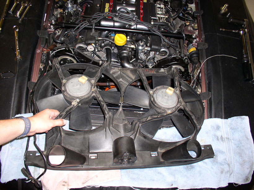
First lay the fan shroud fans facing down over the top of the radiator as shown in the picture. We'll be installing the wiring harness first.
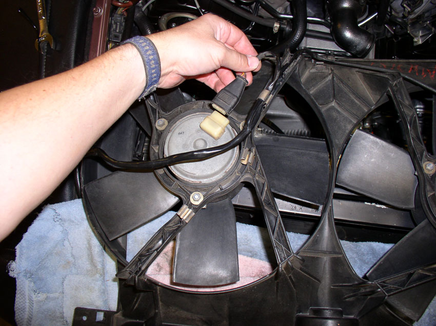
Connect the fan plugs first. The nearest plug on the harness goes to the left fan as shown in the pic while the plug at the end of the harness goes to the right fan.
Next, lay the harness into the spring clips attached to the fan shroud backing as shown below. Leave the harness out of the 2 top most clips because you will need the slack in the harness to manuever the shroud into place.
Tilt the shroud up and begin sliding it down the backside of the radiator.
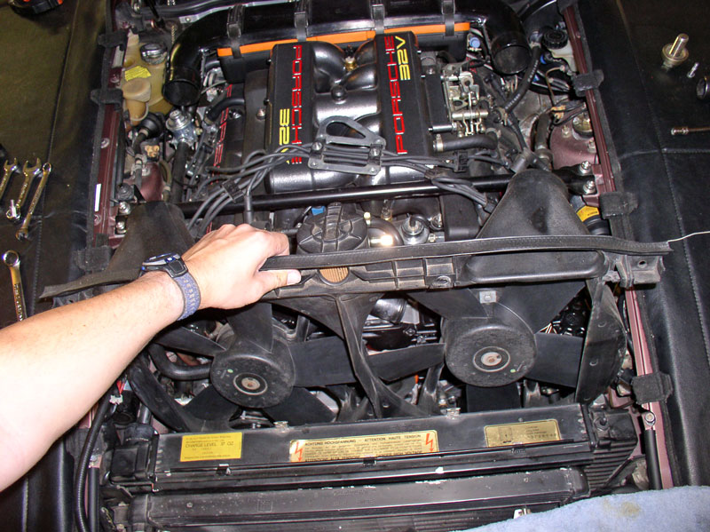
Grab the air pump hose and pull upward as shown and leave in place.
Tilt the shroud downward on the left side and position into place as shown in the pic below.
Position the left side of the shroud into place where the locking lip engages the radiator tank as shown in the pic.
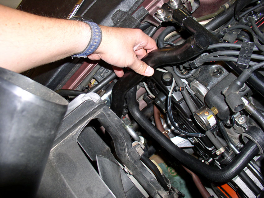
Manuever the right side of the shroud down and into place. The tight spot will be with the upper oil cooler hose fitting. With some manuevering, it will slide into place.
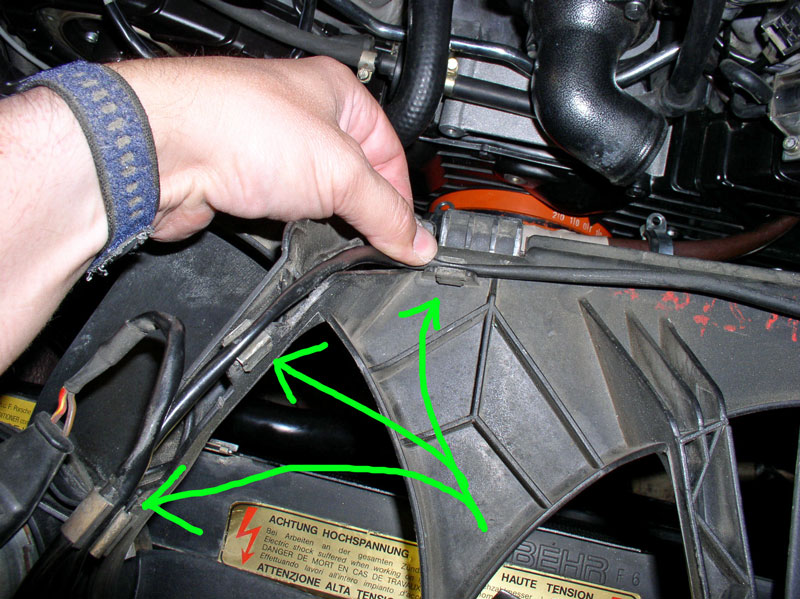
Make sure the locking lip on both sides of the shroud engage the radiator as shown in the pic and ensure the shroud is in front of the aluminum radiator tabs at the top of the radiator as shown below.
From underneath, ensure all the locking tabs are fully instered into their respective slots at the bottom of the shroud as shown below.
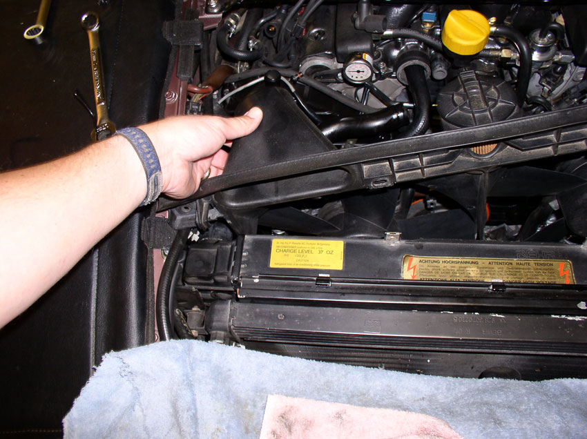
Lastly, secure the shroud to the radiator using the two 10mm screws as shown. Then insert the wiring harness into the 2 top most clips in the fan shroud from a few step back.
Next, we'll install accessory belts and pulleys.....
Continued...
Connect the fan plugs first. The nearest plug on the harness goes to the left fan as shown in the pic while the plug at the end of the harness goes to the right fan.
Next, lay the harness into the spring clips attached to the fan shroud backing as shown below. Leave the harness out of the 2 top most clips because you will need the slack in the harness to manuever the shroud into place.
Tilt the shroud up and begin sliding it down the backside of the radiator.
Grab the air pump hose and pull upward as shown and leave in place.
Tilt the shroud downward on the left side and position into place as shown in the pic below.
Position the left side of the shroud into place where the locking lip engages the radiator tank as shown in the pic.
Manuever the right side of the shroud down and into place. The tight spot will be with the upper oil cooler hose fitting. With some manuevering, it will slide into place.
Make sure the locking lip on both sides of the shroud engage the radiator as shown in the pic and ensure the shroud is in front of the aluminum radiator tabs at the top of the radiator as shown below.
From underneath, ensure all the locking tabs are fully instered into their respective slots at the bottom of the shroud as shown below.
Lastly, secure the shroud to the radiator using the two 10mm screws as shown. Then insert the wiring harness into the 2 top most clips in the fan shroud from a few step back.
Next, we'll install accessory belts and pulleys.....
Continued...