

Timing Belt and Water Pump Procedure w/pics
 01-01-2010, 08:19 PM
#16
Three Wheelin'
Thread Starter
Join Date: Sep 2007
Location: Ridgecrest, California
Posts: 1,363
Likes: 0
Received 149 Likes
on
33 Posts
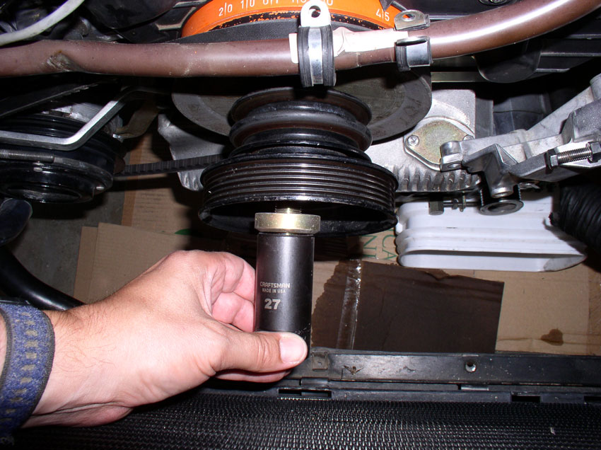
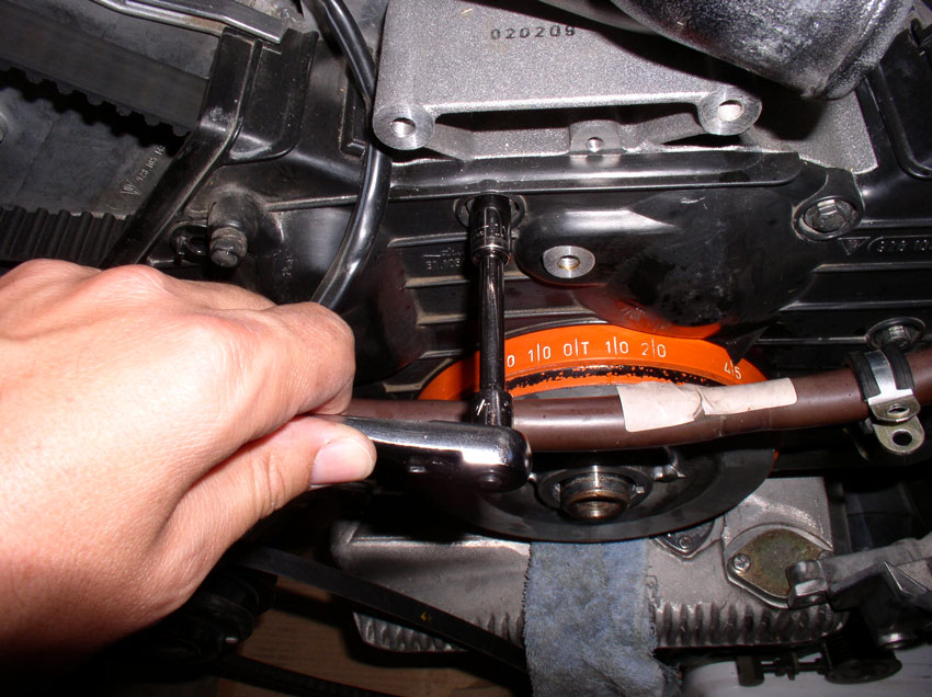
With the crank shaft properly locked down, you can now loosen and remove the crank shaft bolt. I used a breaker bar and the 6-point deep socket. Apply force in the counter clockwise direction to break the bolt loose. If you need more leverage, you can slide an iron pipe over the handle of your breaker bar to give more leverage. Since I had the bolt off before, I did not need the extension pipe for this removal.
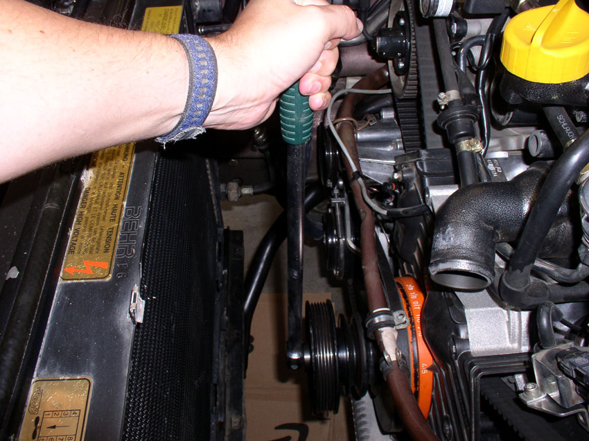
Once the bolt is loose, remove it and set it aside.
If the accessory pulleys do not come off when you pull on them, you can tap them slightly with a rubber mallet as shown below.
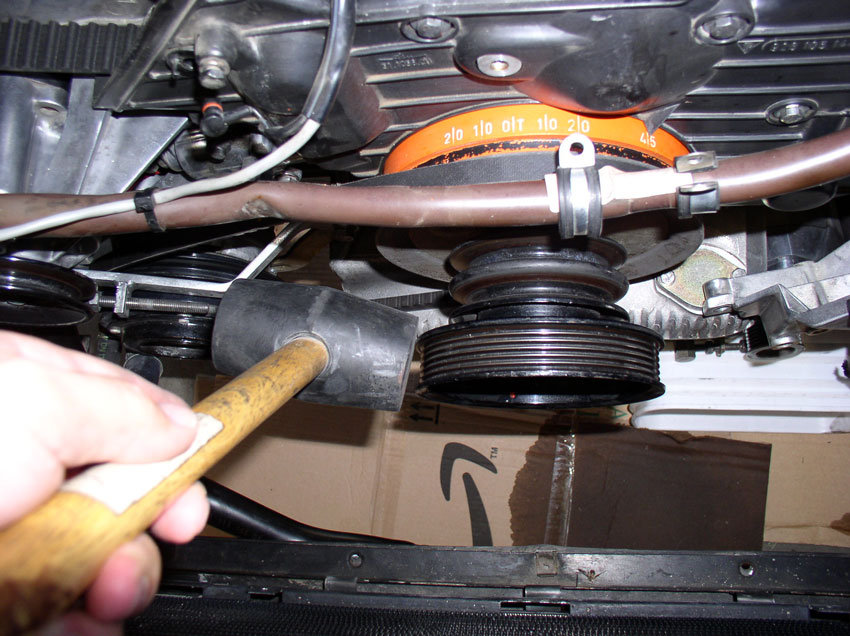
Once the pulleys are loose, remove them.
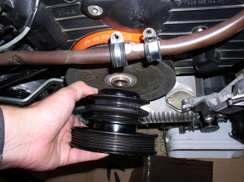
There seemed to be a little bit of rust corrosion holding the A/C pulley onto the crank shaft. I sprayed a little aero-kroil lubricating spray and let is soak in a few mintues.
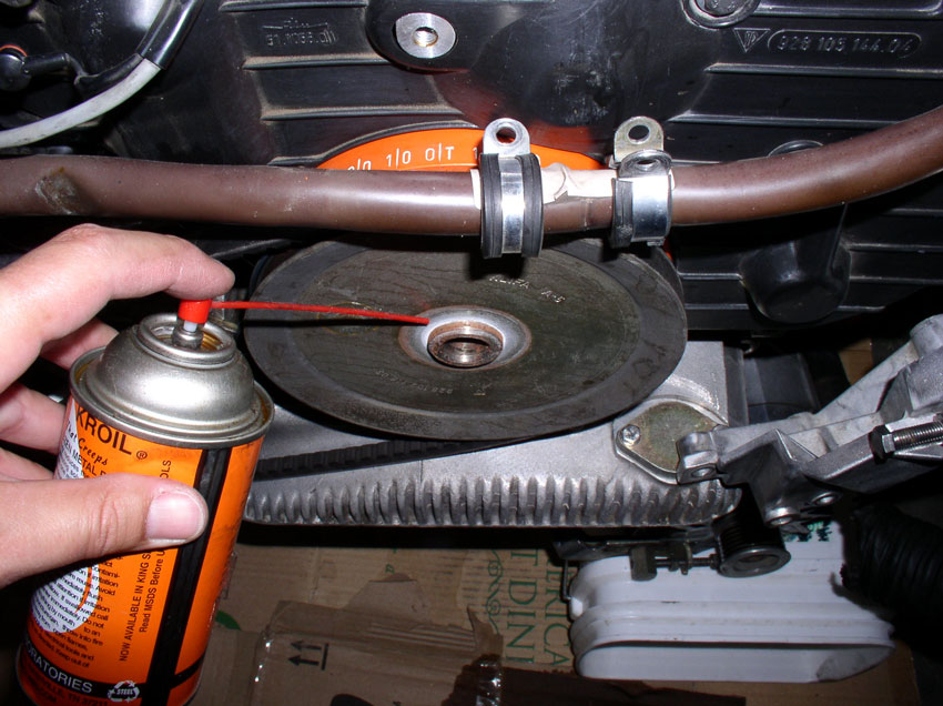
It still wouldn't budge so I put the crank bolt back in and applied a 3-jaw puller to the pulley.....
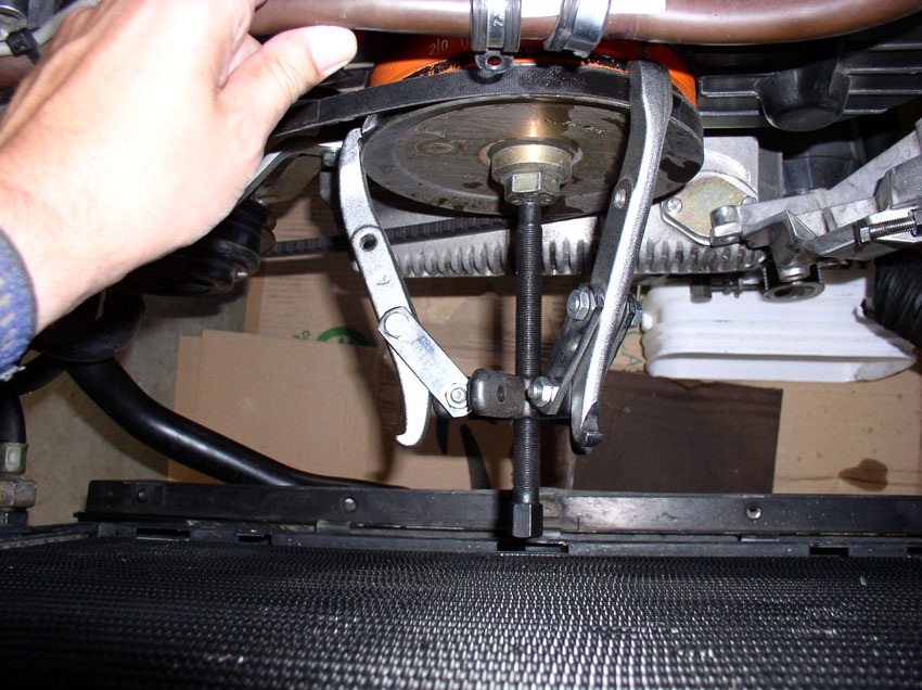
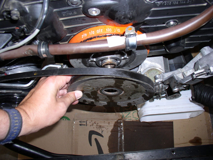
....and it came right off. Remove the belt from tlhe pulley and set the pulley aside. You do not have to remove the belt from the A/C compressor. Just lay it out of the way.
Next, we can remove the center timing belt cover. It is secured with three 10mm bolts and a 13mm bolt. Remove the upper left 10mm bolt as shown.
Followed by removing the upper right 10mm bolt.
Then remove the center 10mm bolt. This is a long bolt and runs through the water pump housing.
Lastly, remove the 13mm bolt that goes through the timing belt tensioner bracket.
Now you should be able to move the center timing belt cover out just a couple of inches. Just enough to.....
....get access to inside the cover to disconnect the belt tensioner wire from the tensioner pivot arm as shown below.
Now, remove the center cover and set aside.
Next, remove the harmonic balancer from the crank shaft. Mine would not come off by hand so I installed the crank bolt and applied the 3-jaw pulley puller.
Continued......
Once the bolt is loose, remove it and set it aside.
If the accessory pulleys do not come off when you pull on them, you can tap them slightly with a rubber mallet as shown below.
Once the pulleys are loose, remove them.
There seemed to be a little bit of rust corrosion holding the A/C pulley onto the crank shaft. I sprayed a little aero-kroil lubricating spray and let is soak in a few mintues.
It still wouldn't budge so I put the crank bolt back in and applied a 3-jaw puller to the pulley.....
....and it came right off. Remove the belt from tlhe pulley and set the pulley aside. You do not have to remove the belt from the A/C compressor. Just lay it out of the way.
Next, we can remove the center timing belt cover. It is secured with three 10mm bolts and a 13mm bolt. Remove the upper left 10mm bolt as shown.
Followed by removing the upper right 10mm bolt.
Then remove the center 10mm bolt. This is a long bolt and runs through the water pump housing.
Lastly, remove the 13mm bolt that goes through the timing belt tensioner bracket.
Now you should be able to move the center timing belt cover out just a couple of inches. Just enough to.....
....get access to inside the cover to disconnect the belt tensioner wire from the tensioner pivot arm as shown below.
Now, remove the center cover and set aside.
Next, remove the harmonic balancer from the crank shaft. Mine would not come off by hand so I installed the crank bolt and applied the 3-jaw pulley puller.
Continued......
 01-01-2010, 08:22 PM
#17
Three Wheelin'
Thread Starter
Join Date: Sep 2007
Location: Ridgecrest, California
Posts: 1,363
Likes: 0
Received 149 Likes
on
33 Posts
After applying the 3-Jaw pulley puller, the harmonic balancer came right off! Remove it and set it aside.
Next we'll work on removing the timing belt tensioner pulley and timing belt
Continued.....
Next we'll work on removing the timing belt tensioner pulley and timing belt
Continued.....
01-01-2010, 08:50 PM
#18
Three Wheelin'
Thread Starter
Join Date: Sep 2007
Location: Ridgecrest, California
Posts: 1,363
Likes: 0
Received 149 Likes
on
33 Posts
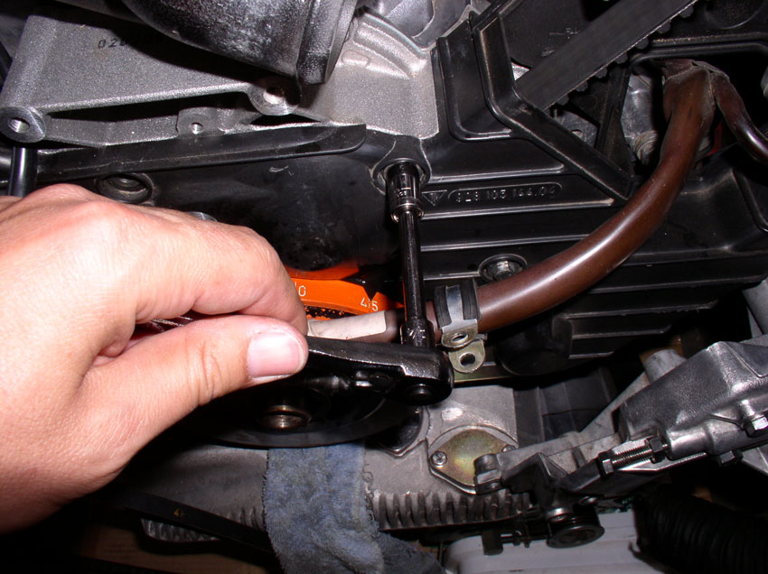
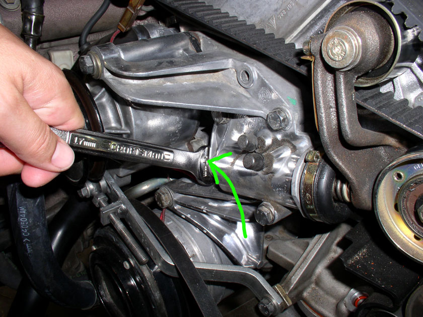
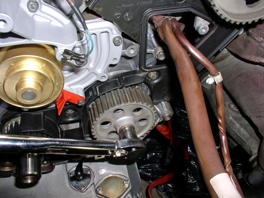
First we need to relax the tension on the timing belt. Belt tension is adjusted using the adjustment bolt at the rear of the tensioner. The adjustment bolt is locked in place with a locking nut. The nut and bolt are both 17mm. Using a 17mm wrench, loosen the adjustment bolt locking nut as shown below.
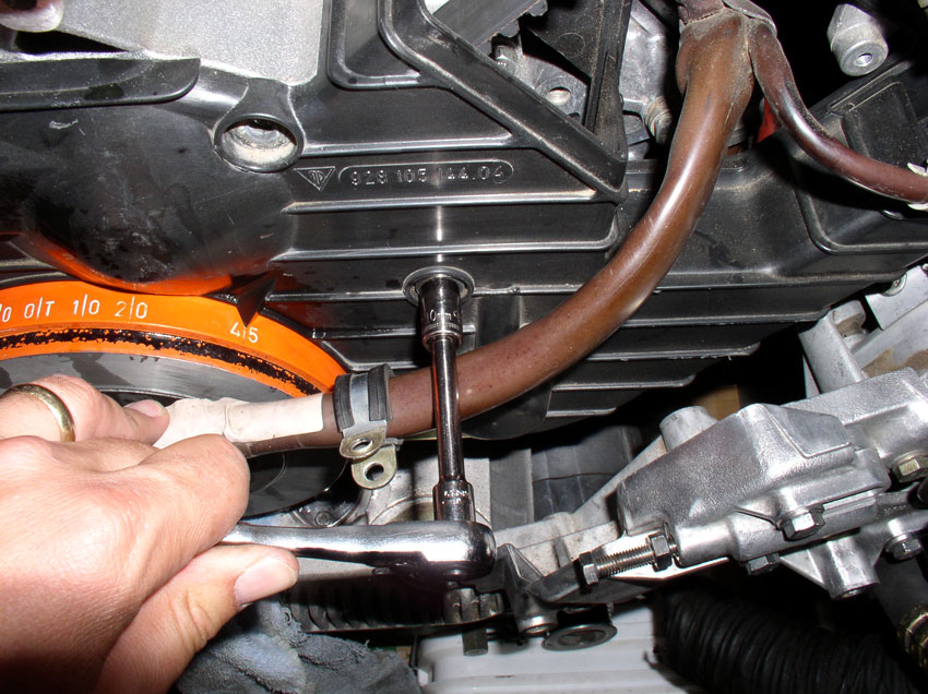
Then loosen (counter clockwise) the tension adjustment bolt. Turn it several turns counter clockwise until.....
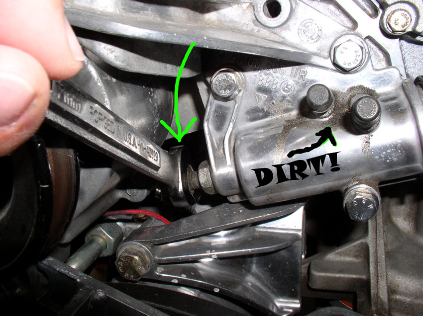
....you have some slack in the timing belt as shown below.
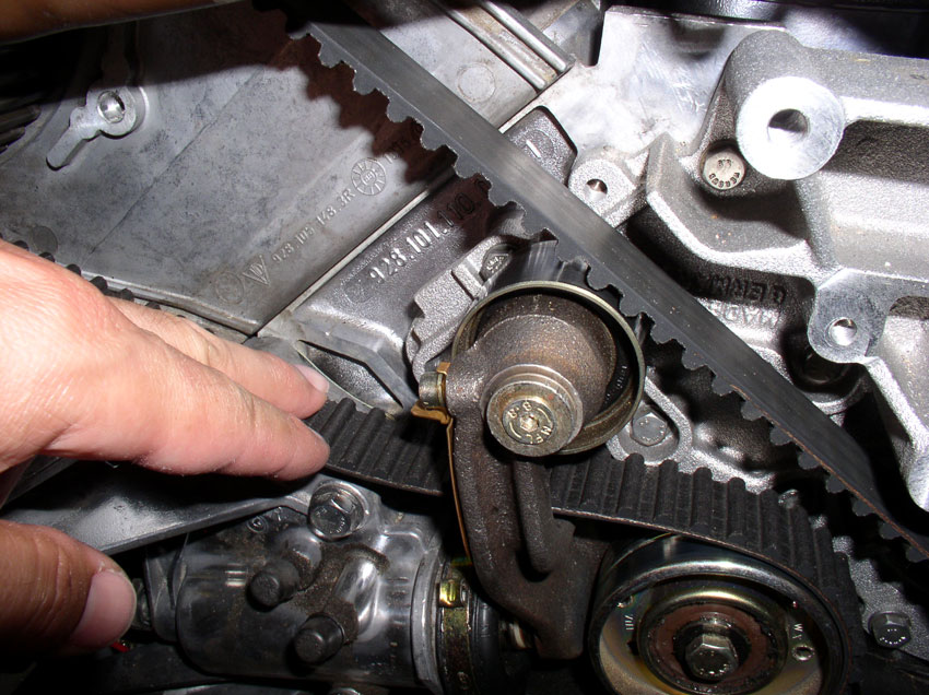
Then you should be able to slide the belt off the passenger timing gear as shown below.
Once the belt is off the passenger timing gear, you should be able to remove the tensioner pulley assembly. The pulley assembly is secured using a small 4mm allen head bolt. These can strip easily if they are stuck so be careful when removing the bolt making sure the allen socket is secure and fully seated in the bolt.
Remove the bolt and washer as shown.
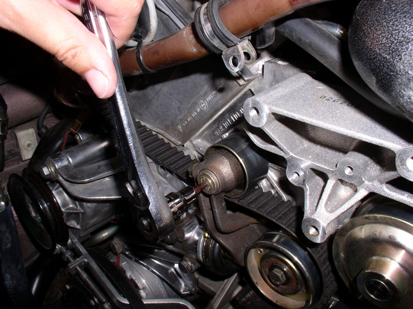
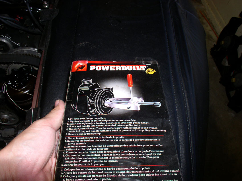
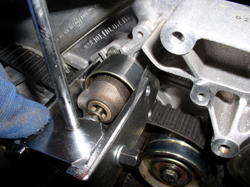
You should be able to pull of the tensioner pulley assembly. However, if your tensioner pulley assembly is stuck on the spindle as mine was, you may need some help getting it off. I used this Power Steering Pulley Puller to get a grip on the idler pulley and pull the assemply off the spindle. It's a common tool and can be found at most automotive stores.
I used an M6 (10mm bolt) the same size bolt that is used to secure the water pump to the block (I had spares) as the counterforce for the puller. Insert the bolt part way into the threads as shown and install the puller.
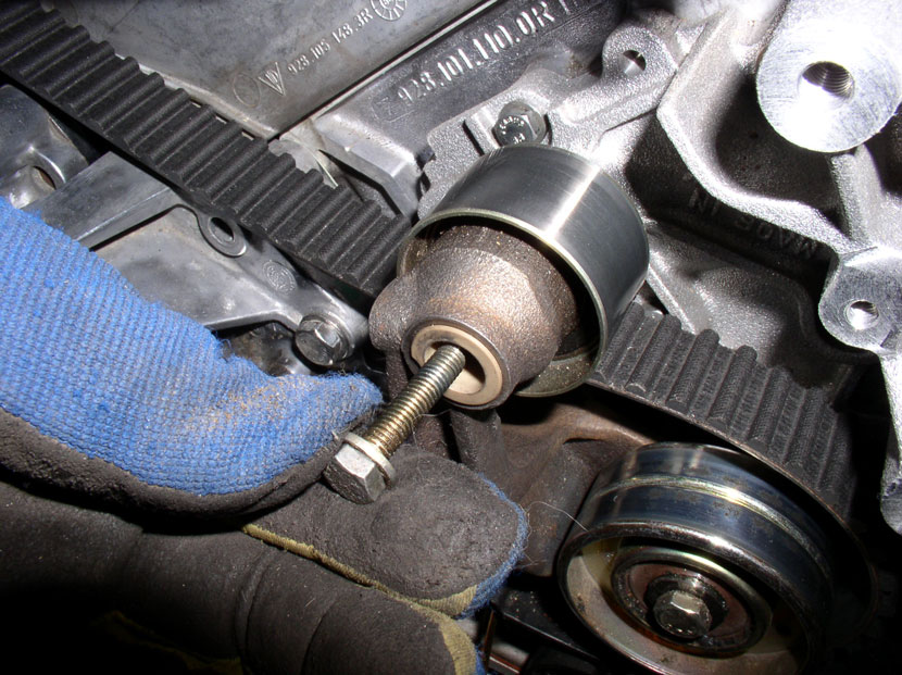
Slowly pull the idler pulley off the spindle....
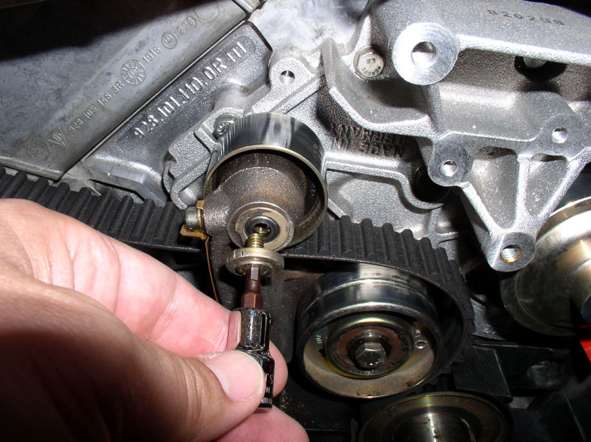
If you need more of the 10mm bolt exposed, simply unscrew it some more and continue pulling with the puller.
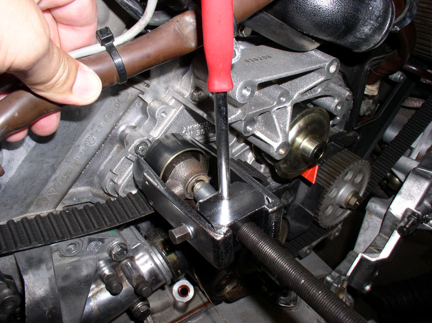
Eventually, the idler pulley comes off the spindle.
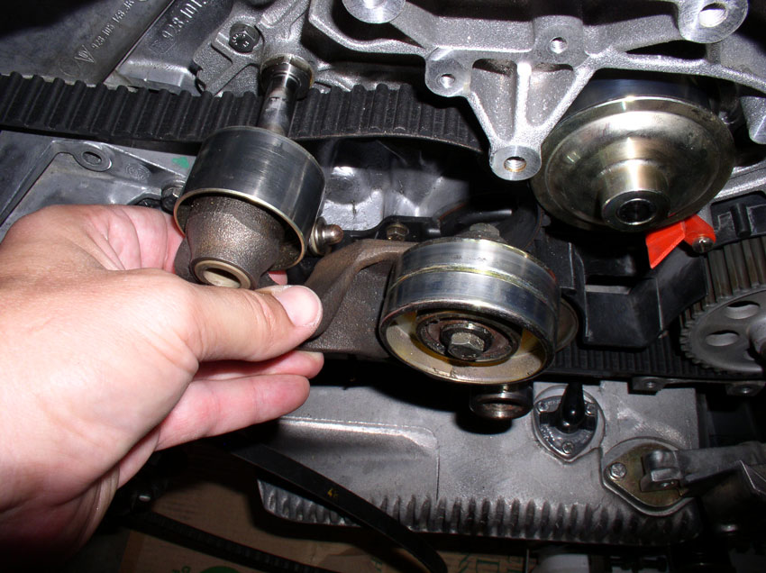
Set aside the tensioner pulley assembly. We'll work on it later to replace the pulley and bushings.

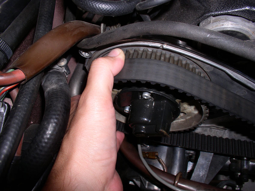
Next, remove the outer timing belt guide from the crank timing belt gear....
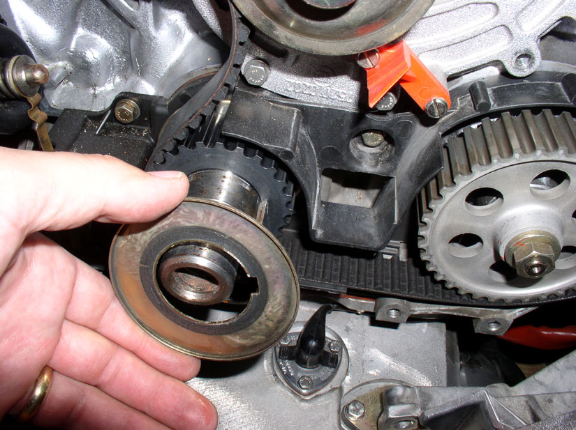
....and slide the timing belt out from the crank gear as shown.
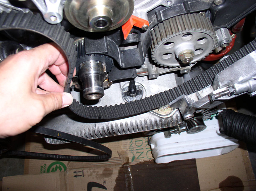
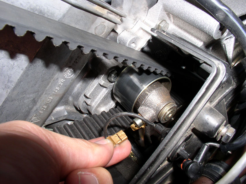
Now the timing belt is ready to come off but we need to disconnect a couple of wiring harnesses in order to remove the belt. We'll start with the small wriing harness that runs along the driver's side of the firewall behind the power steering reservoir mounting bracket. You can trace this harness to its connection point at the small box pictured below. Pop the protective top off to expose the phillips screw underneath as shown.
Continued.....
Then loosen (counter clockwise) the tension adjustment bolt. Turn it several turns counter clockwise until.....
....you have some slack in the timing belt as shown below.
Then you should be able to slide the belt off the passenger timing gear as shown below.
Once the belt is off the passenger timing gear, you should be able to remove the tensioner pulley assembly. The pulley assembly is secured using a small 4mm allen head bolt. These can strip easily if they are stuck so be careful when removing the bolt making sure the allen socket is secure and fully seated in the bolt.
Remove the bolt and washer as shown.
You should be able to pull of the tensioner pulley assembly. However, if your tensioner pulley assembly is stuck on the spindle as mine was, you may need some help getting it off. I used this Power Steering Pulley Puller to get a grip on the idler pulley and pull the assemply off the spindle. It's a common tool and can be found at most automotive stores.
I used an M6 (10mm bolt) the same size bolt that is used to secure the water pump to the block (I had spares) as the counterforce for the puller. Insert the bolt part way into the threads as shown and install the puller.
Slowly pull the idler pulley off the spindle....
If you need more of the 10mm bolt exposed, simply unscrew it some more and continue pulling with the puller.
Eventually, the idler pulley comes off the spindle.
Set aside the tensioner pulley assembly. We'll work on it later to replace the pulley and bushings.
Next, remove the outer timing belt guide from the crank timing belt gear....
....and slide the timing belt out from the crank gear as shown.
Now the timing belt is ready to come off but we need to disconnect a couple of wiring harnesses in order to remove the belt. We'll start with the small wriing harness that runs along the driver's side of the firewall behind the power steering reservoir mounting bracket. You can trace this harness to its connection point at the small box pictured below. Pop the protective top off to expose the phillips screw underneath as shown.
Continued.....
01-01-2010, 09:06 PM
#19
Three Wheelin'
Thread Starter
Join Date: Sep 2007
Location: Ridgecrest, California
Posts: 1,363
Likes: 0
Received 149 Likes
on
33 Posts
Using a phillips screwdriver, loosen and remove the phillips screw securing the wiring harness as shown.
Back out the harness from behind the power steering reservoir bracket as shown.
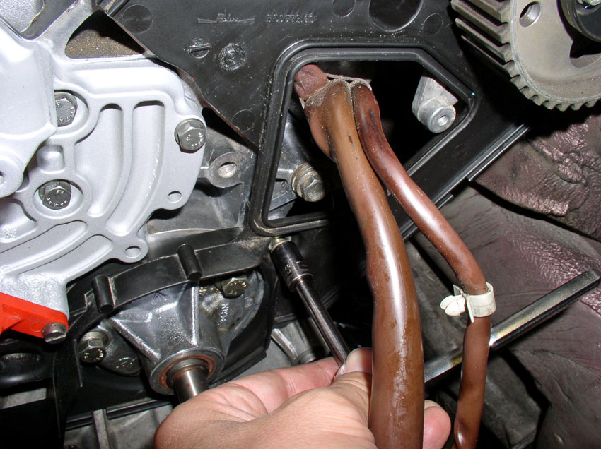
Continue backing out the harness from behind the power steering hoses as shown. Now, the small harness should be free.
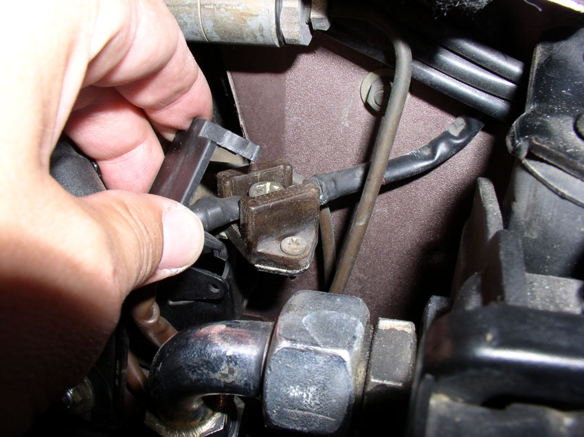
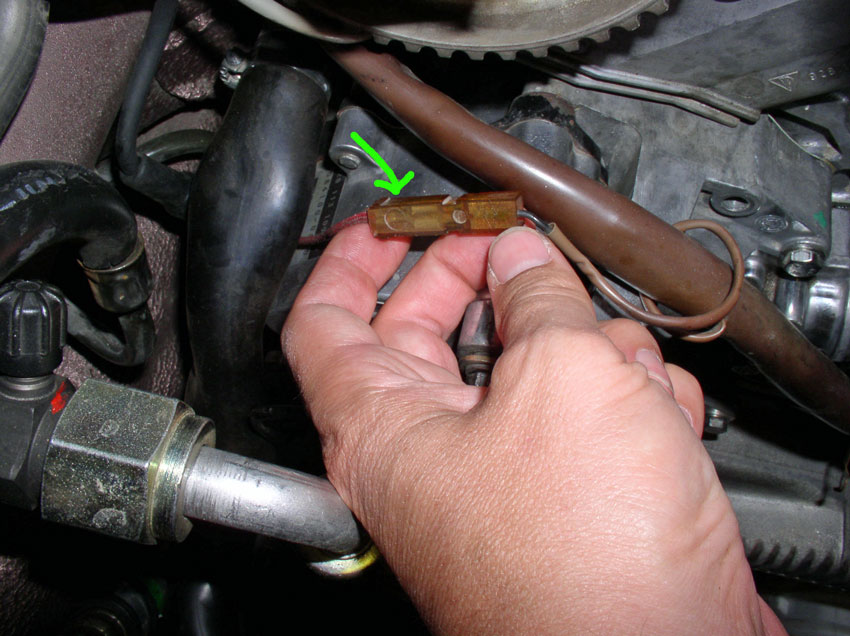
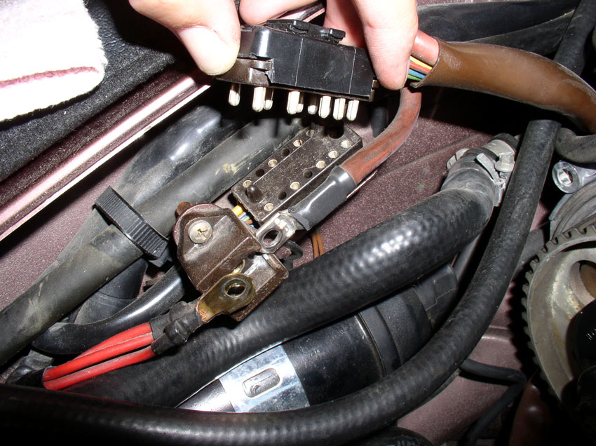
Next, we need to do the same for larger wiring harness pictured below. First, disconnect the power wire to the A/C compressor (the red wire that comes out of the brown square plastic connector pictured below. Pull the red wire out from the connector.
Remove the harness clamp that is attached to the engine lift hook at the passenger front side of the engine as pictured below. The clamp is secured with a 10mm bolt. Loosen and remove the 10mm bolt. Remove the harness from the clamp.
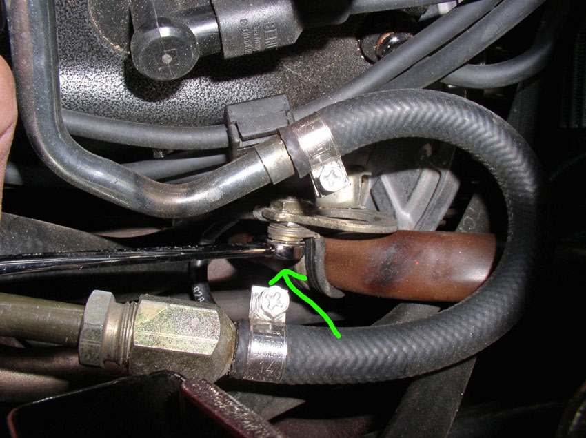
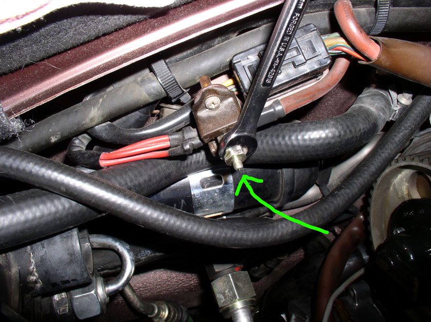
Loosen and remove the 11mm charge post bolt as pictured below. Pull the harness wire out and replace the bolt in the connector.
Lift up and remove the upper half of the 14-pin harness connector as shown below.
Back feed the harness back behind the cam cover back plate as shown.
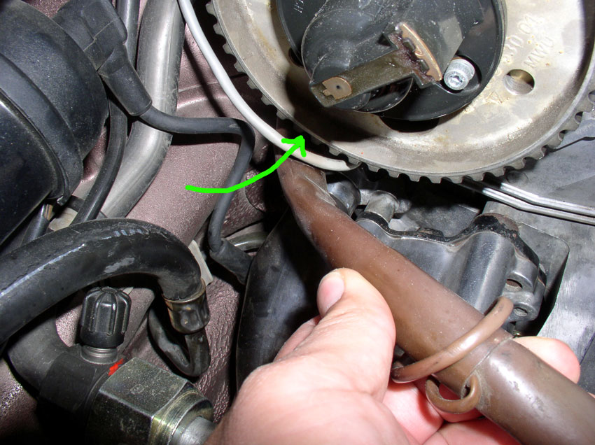
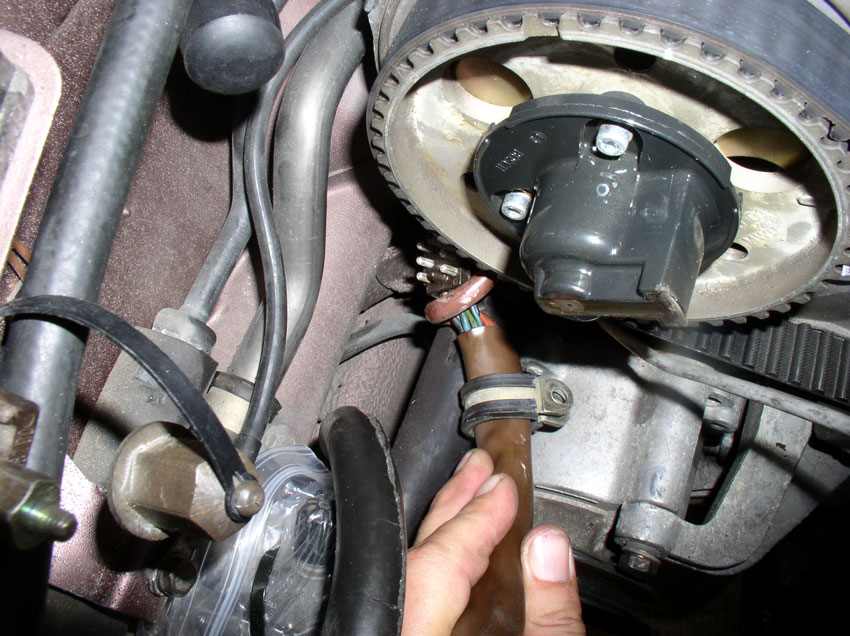
Pull the harness all they way out from behind the cam as shown. Now the large harness is free and you can remove the timing belt.
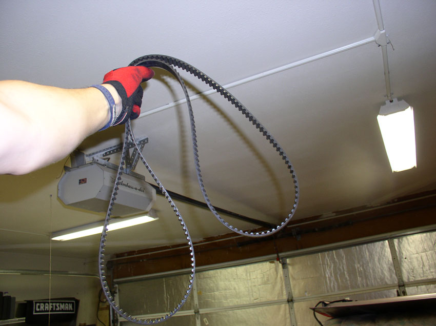
Once the timing belt is free, you can do the victory dance!
Removing the water pump is next.
Continued.....
Back out the harness from behind the power steering reservoir bracket as shown.
Continue backing out the harness from behind the power steering hoses as shown. Now, the small harness should be free.
Next, we need to do the same for larger wiring harness pictured below. First, disconnect the power wire to the A/C compressor (the red wire that comes out of the brown square plastic connector pictured below. Pull the red wire out from the connector.
Remove the harness clamp that is attached to the engine lift hook at the passenger front side of the engine as pictured below. The clamp is secured with a 10mm bolt. Loosen and remove the 10mm bolt. Remove the harness from the clamp.
Loosen and remove the 11mm charge post bolt as pictured below. Pull the harness wire out and replace the bolt in the connector.
Lift up and remove the upper half of the 14-pin harness connector as shown below.
Back feed the harness back behind the cam cover back plate as shown.
Pull the harness all they way out from behind the cam as shown. Now the large harness is free and you can remove the timing belt.
Once the timing belt is free, you can do the victory dance!
Removing the water pump is next.
Continued.....
01-01-2010, 09:39 PM
#20
Three Wheelin'
Thread Starter
Join Date: Sep 2007
Location: Ridgecrest, California
Posts: 1,363
Likes: 0
Received 149 Likes
on
33 Posts
The water pump is secured with 13 10mm bolts. At this point, you can begin removing all the bolts.
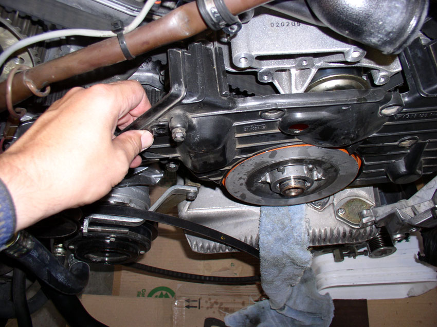
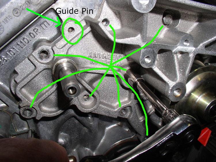
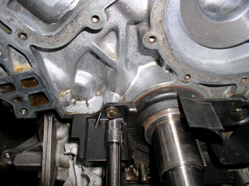
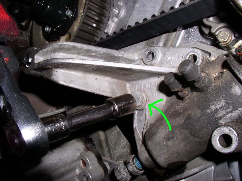
There are 8 bolts to the left of the pulley as depicted in the below picture. The remaining 5 bolts are to the right of the pulley. You will also notice that 5 of the bolts are shorter than the others. These 5 bolts are matched with the holes that are recessed in the water pump housing - there are 5 of them. Finallly, notice the guide pins. There is one on each side of the water pump. Depicted in the picture below is the guide pin on the left side of the water pump. There is another on the right side of the water pump. These are great for locating the water pump properly when installing. However, they can be bent or broken off if the water pump is forced off at an angle.
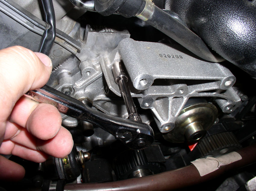
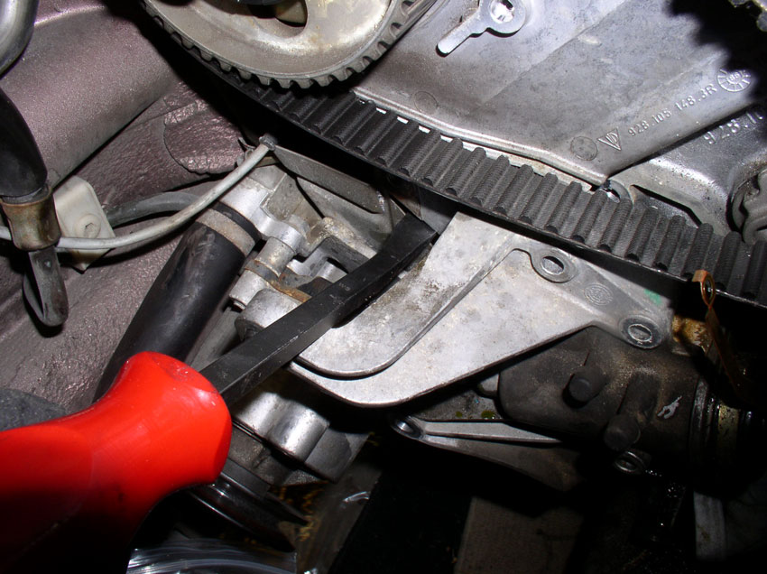
When all the bolts have been removed, you can pull the water pump off. It will probably be stuck on so you may need to pry it off. The method that works well for me is to gently pry the pump off by inserting a large flat blade screwdriver between the engine block (where the engine block number is stamped) and the water pump housing. Do not pry much, just enough to break the bond and allow you to "walk" the pump off the guide pins. Pull on one side then the other then the other side and so on until the pump comes off.
Once the pump is off, set it aside.
There are 8 bolts to the left of the pulley as depicted in the below picture. The remaining 5 bolts are to the right of the pulley. You will also notice that 5 of the bolts are shorter than the others. These 5 bolts are matched with the holes that are recessed in the water pump housing - there are 5 of them. Finallly, notice the guide pins. There is one on each side of the water pump. Depicted in the picture below is the guide pin on the left side of the water pump. There is another on the right side of the water pump. These are great for locating the water pump properly when installing. However, they can be bent or broken off if the water pump is forced off at an angle.
When all the bolts have been removed, you can pull the water pump off. It will probably be stuck on so you may need to pry it off. The method that works well for me is to gently pry the pump off by inserting a large flat blade screwdriver between the engine block (where the engine block number is stamped) and the water pump housing. Do not pry much, just enough to break the bond and allow you to "walk" the pump off the guide pins. Pull on one side then the other then the other side and so on until the pump comes off.
Once the pump is off, set it aside.
01-01-2010, 09:51 PM
#21
Three Wheelin'
Dwayne, do you have the same style of write up w/pics for your OB cars somewhere?
01-01-2010, 10:10 PM
#22
Three Wheelin'
Thread Starter
Join Date: Sep 2007
Location: Ridgecrest, California
Posts: 1,363
Likes: 0
Received 149 Likes
on
33 Posts
01-01-2010, 10:47 PM
#23
Three Wheelin'
Thread Starter
Join Date: Sep 2007
Location: Ridgecrest, California
Posts: 1,363
Likes: 0
Received 149 Likes
on
33 Posts
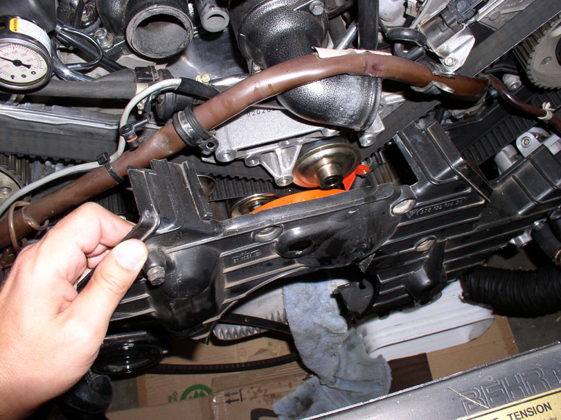
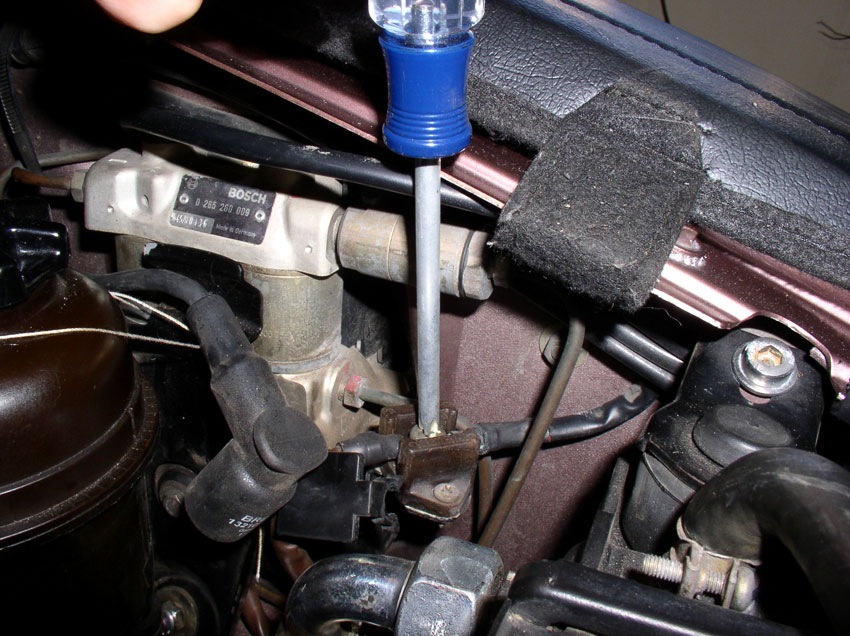
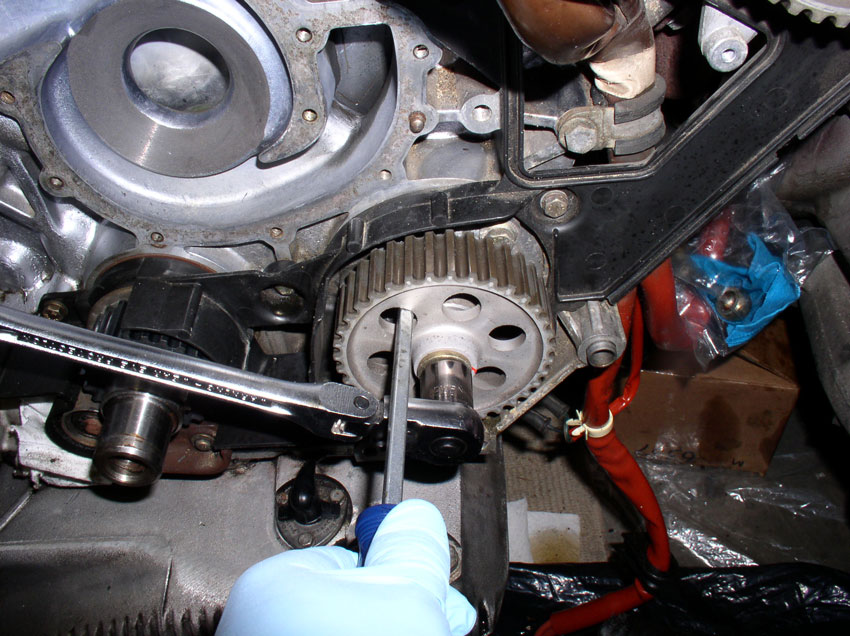
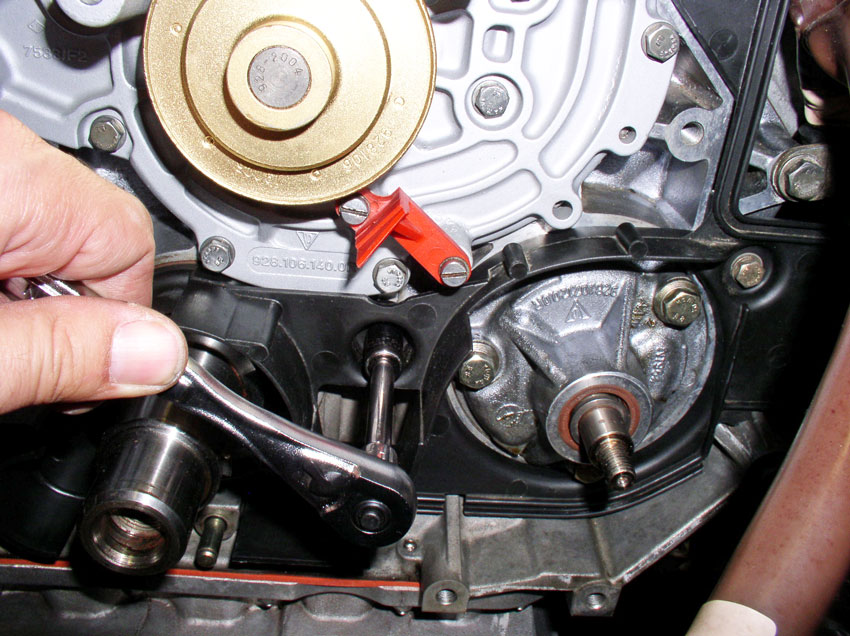
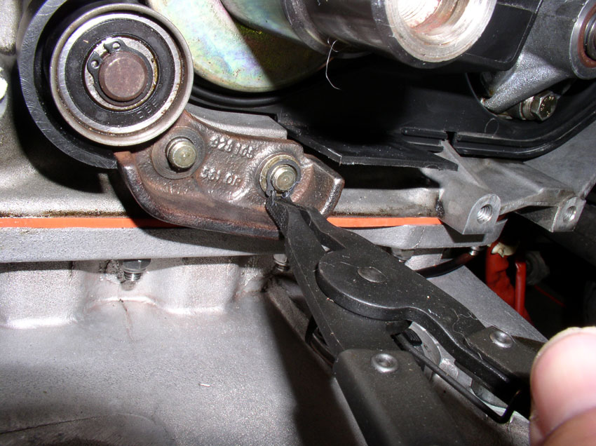
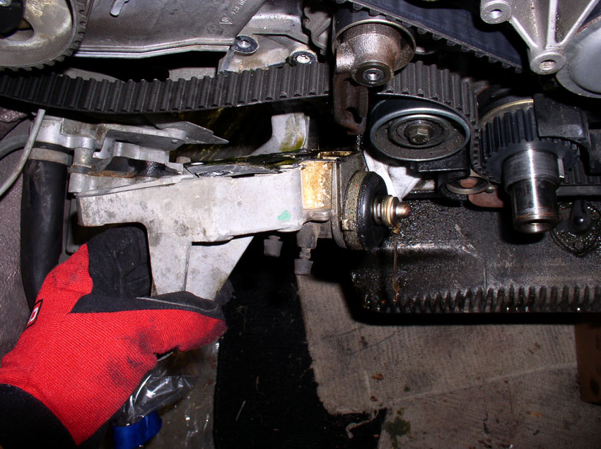
If you would like to replace a leaking o-ring or seal on the oil pump, this next section should help. However, if not, you can skip to Chapter 13 to resume with the regularly scheduled program of timing belt and water pump. First, we remove the oil pump gear. It is secured with a 17mm nut. You can counterhold the gear using a large flat blade screwdriver or pry bar by inserting the screwdriver in one of the gear holes and catching one of the casting ridges behind the gear as shown below.
Once the gear nut is loosened, remove the nut and washer.
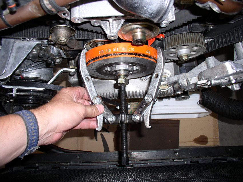
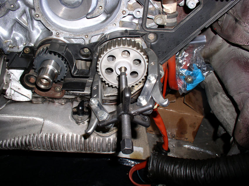
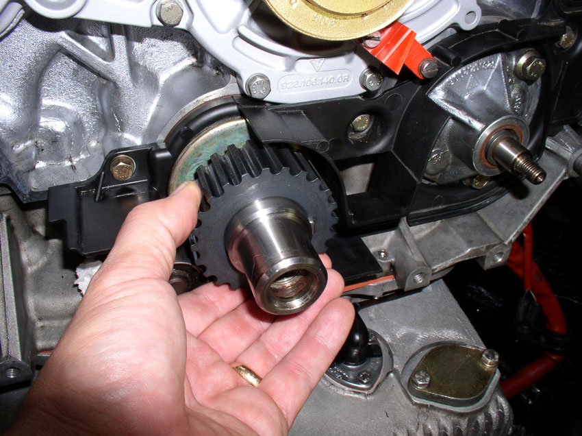
You can try to pull off the gear by hand but most likely it will be stuck. Mine was so I used a 2-Jaw puller and it came right off.
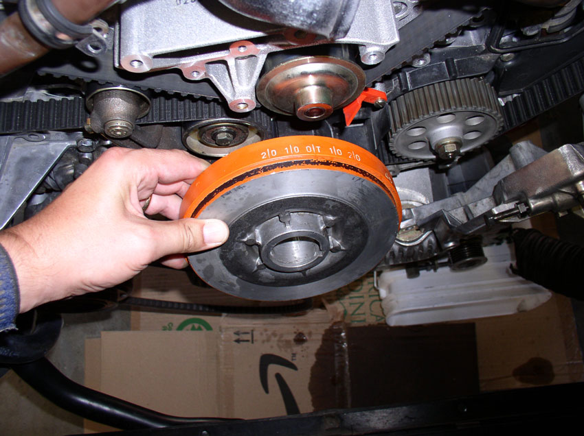
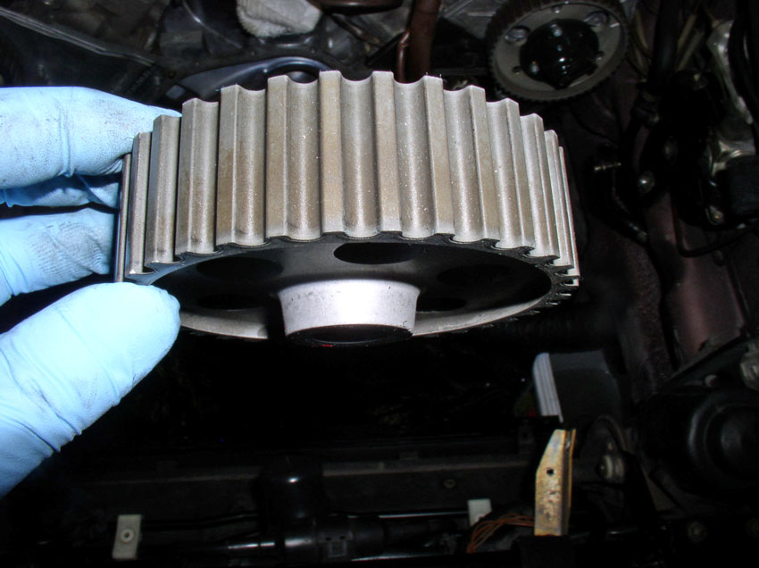
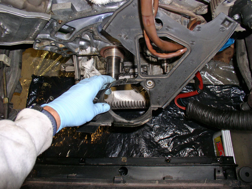
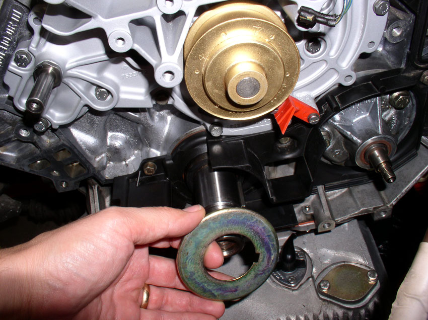
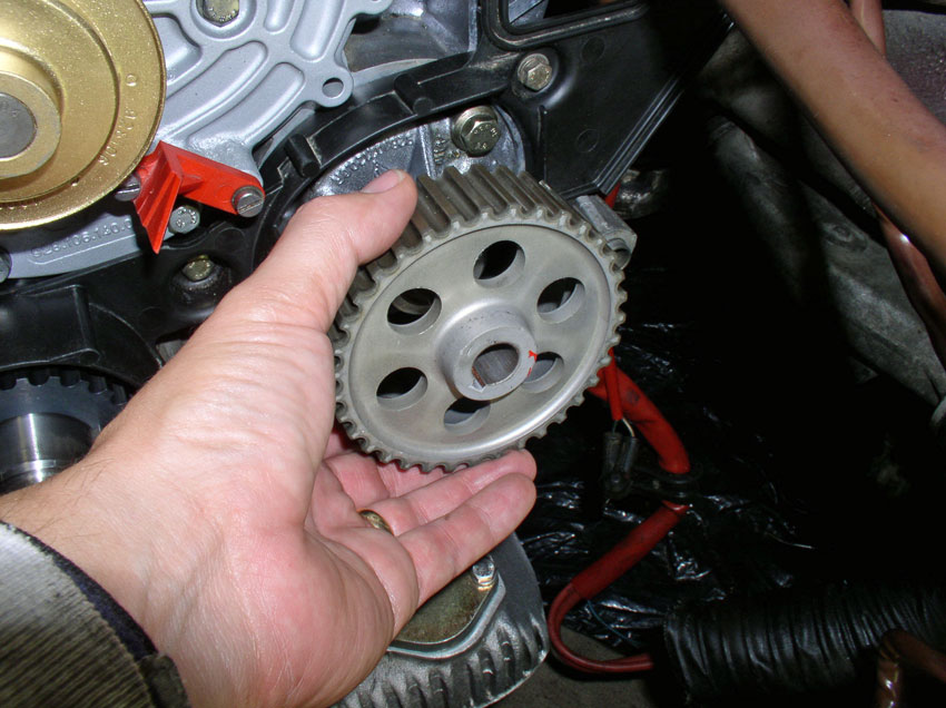
Once the gear is off, inspect the coating on the gear. The coating can wear off and expose the soft metal below. If the gear looks like shiny metal, the coating has worn off and the gear should be replaced. If the gear looks like the one pictured below, the coating is still intact and can be put back into service. This particular gear had about 34K miles on it.
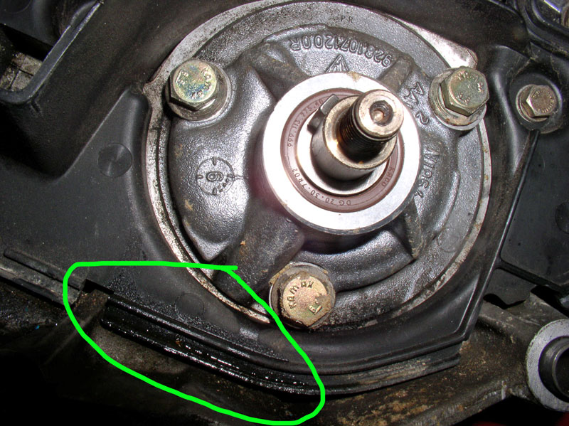
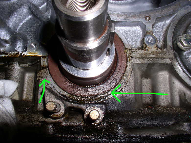
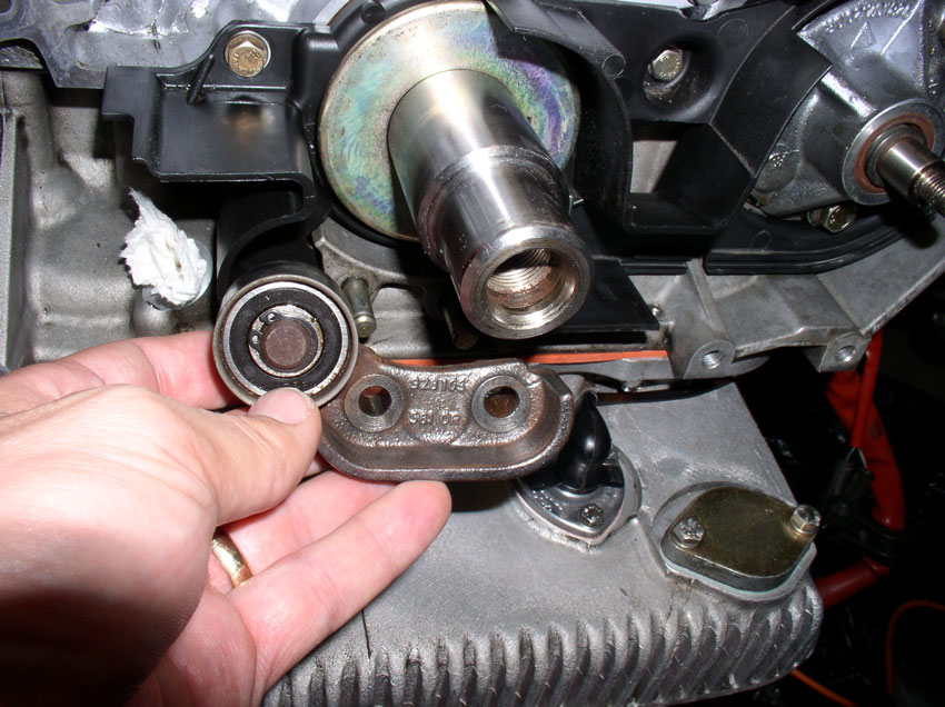
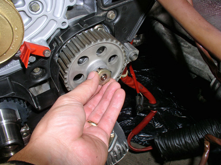
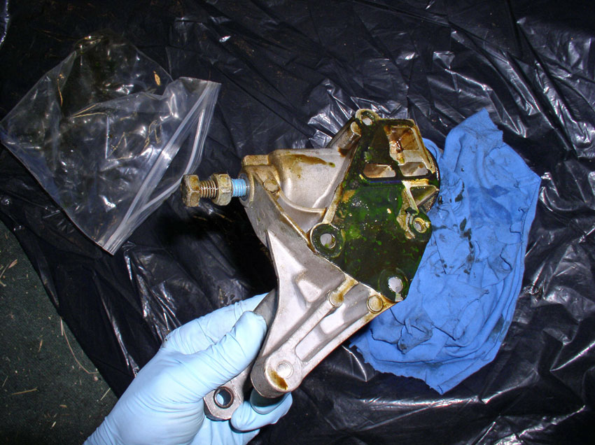
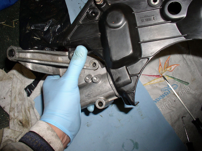
Once the gear is off, you can inspect the seals and mating surfaces to look for leaks. You can see here with mine that there is some weeping or light leaking below the oil pump. The brown seal around the pump spindle above the circled area appears clean with no leaks. The lower leak is probably due to a worn out O-ring on the pump housing. It appears the oil pump can be removed without removing the rear plastic cam cover shown in the background. However, since I wanted to clean it all up, I removed the cam cover as illustrated in the following steps.
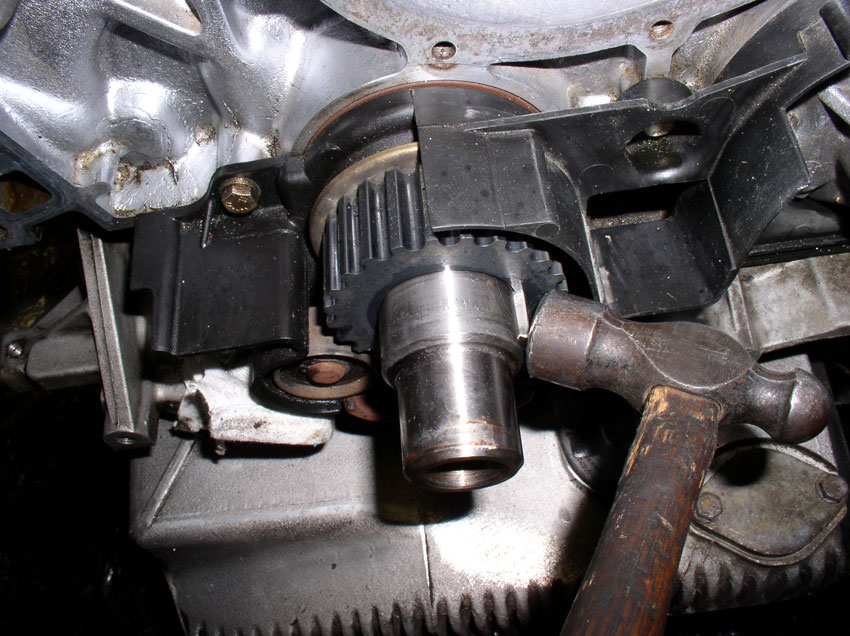
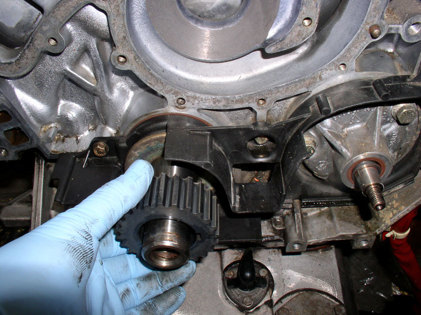
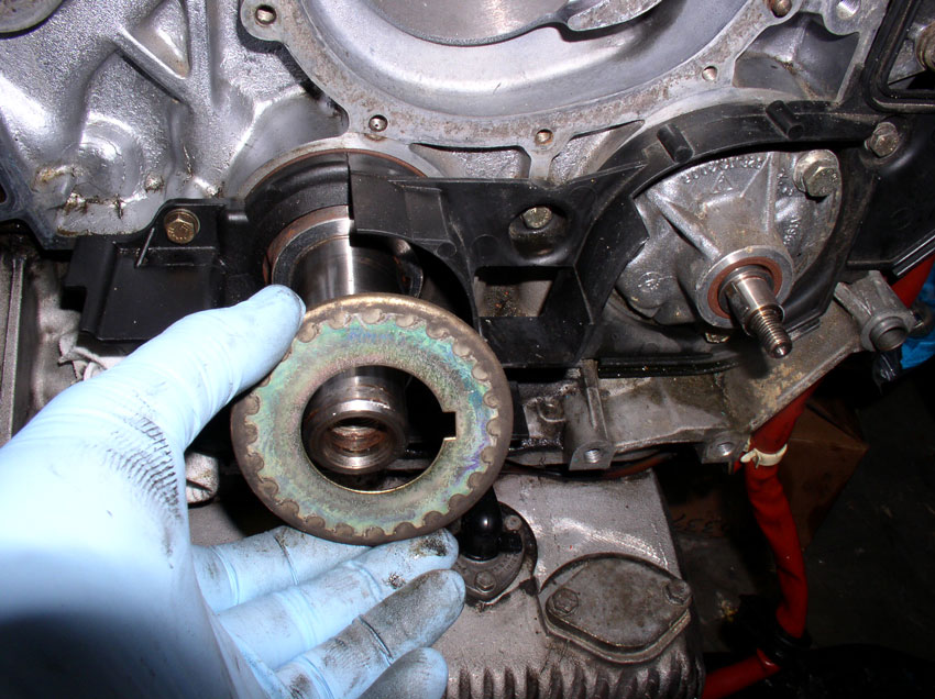
First, remove the crank timing belt gear from the crank shaft. Sometimes the gear will not slide off because the "key" is angled or wedged in at an angle. If the gear does not slide over the key, you can gently tap the key to align it as shown below.
The gear should slide off at this point.
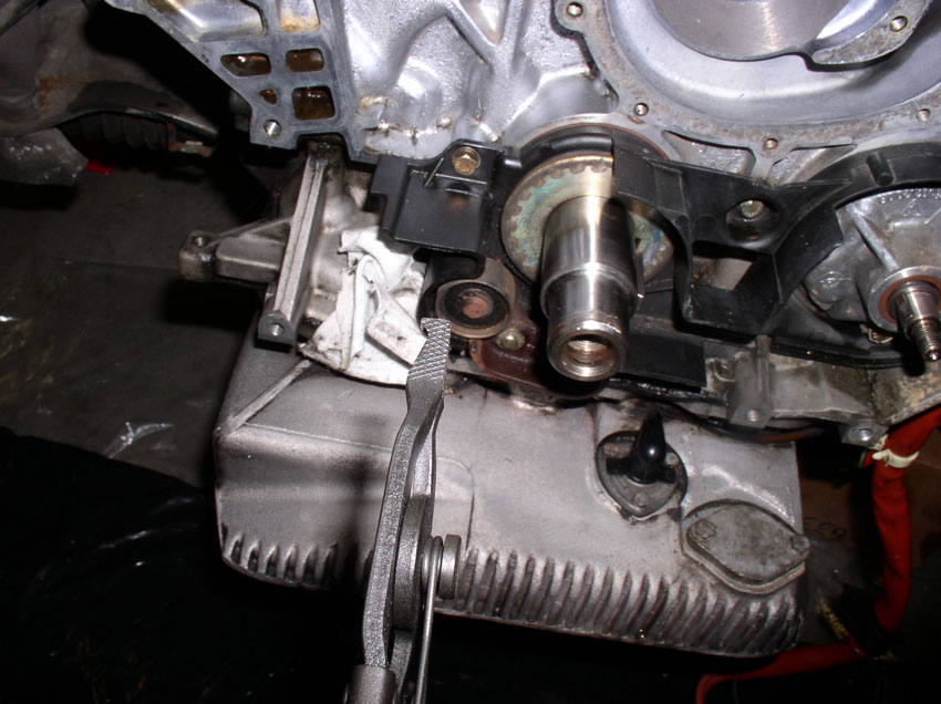
Next, remove the pulley below the crank shaft. You will need a small pair of circlip pliers.
Remove both of the circlips on the pulley assembly as shown.
Remove both of the washers behind the circlips as shown.
Remove the pulley assembly. As you can see from the pic, the assembly never gets used or comes in contact with the belt. I'm not sure why it's still present.
Remove the inner timing belt guide from the crank shaft.
The rear timing belt cover is secured with 5 bolts. First, remove the 5mm allen head bolt that resides behind the metal cam cover backplate as shown. You will notice it also secures a grounding wire between the engine and the fender at the coil mounting bracket (see pic). Remove the bolt.
There is another 5mm allen head bolt on the other side of the cam shaft between the head and the metal cam cover backplate. Remove the bolt.
Next, remove the center 10mm bolt as pictured.
Continued....
Once the gear nut is loosened, remove the nut and washer.
You can try to pull off the gear by hand but most likely it will be stuck. Mine was so I used a 2-Jaw puller and it came right off.
Once the gear is off, inspect the coating on the gear. The coating can wear off and expose the soft metal below. If the gear looks like shiny metal, the coating has worn off and the gear should be replaced. If the gear looks like the one pictured below, the coating is still intact and can be put back into service. This particular gear had about 34K miles on it.
Once the gear is off, you can inspect the seals and mating surfaces to look for leaks. You can see here with mine that there is some weeping or light leaking below the oil pump. The brown seal around the pump spindle above the circled area appears clean with no leaks. The lower leak is probably due to a worn out O-ring on the pump housing. It appears the oil pump can be removed without removing the rear plastic cam cover shown in the background. However, since I wanted to clean it all up, I removed the cam cover as illustrated in the following steps.
First, remove the crank timing belt gear from the crank shaft. Sometimes the gear will not slide off because the "key" is angled or wedged in at an angle. If the gear does not slide over the key, you can gently tap the key to align it as shown below.
The gear should slide off at this point.
Next, remove the pulley below the crank shaft. You will need a small pair of circlip pliers.
Remove both of the circlips on the pulley assembly as shown.
Remove both of the washers behind the circlips as shown.
Remove the pulley assembly. As you can see from the pic, the assembly never gets used or comes in contact with the belt. I'm not sure why it's still present.
Remove the inner timing belt guide from the crank shaft.
The rear timing belt cover is secured with 5 bolts. First, remove the 5mm allen head bolt that resides behind the metal cam cover backplate as shown. You will notice it also secures a grounding wire between the engine and the fender at the coil mounting bracket (see pic). Remove the bolt.
There is another 5mm allen head bolt on the other side of the cam shaft between the head and the metal cam cover backplate. Remove the bolt.
Next, remove the center 10mm bolt as pictured.
Continued....
01-01-2010, 10:52 PM
#24
Three Wheelin'
Thread Starter
Join Date: Sep 2007
Location: Ridgecrest, California
Posts: 1,363
Likes: 0
Received 149 Likes
on
33 Posts
Remove the 10mm bolt to the right.....
....and the 10mm bolt to the left on the cover.
At this point, you can remove the back cover. You will have to feed the wiring harnesses through just as you did with the timing belt.
Now you can clean the area before removing the pump which is detailed next.
Continued.....
....and the 10mm bolt to the left on the cover.
At this point, you can remove the back cover. You will have to feed the wiring harnesses through just as you did with the timing belt.
Now you can clean the area before removing the pump which is detailed next.
Continued.....
01-01-2010, 11:13 PM
#25
Three Wheelin'
Thread Starter
Join Date: Sep 2007
Location: Ridgecrest, California
Posts: 1,363
Likes: 0
Received 149 Likes
on
33 Posts
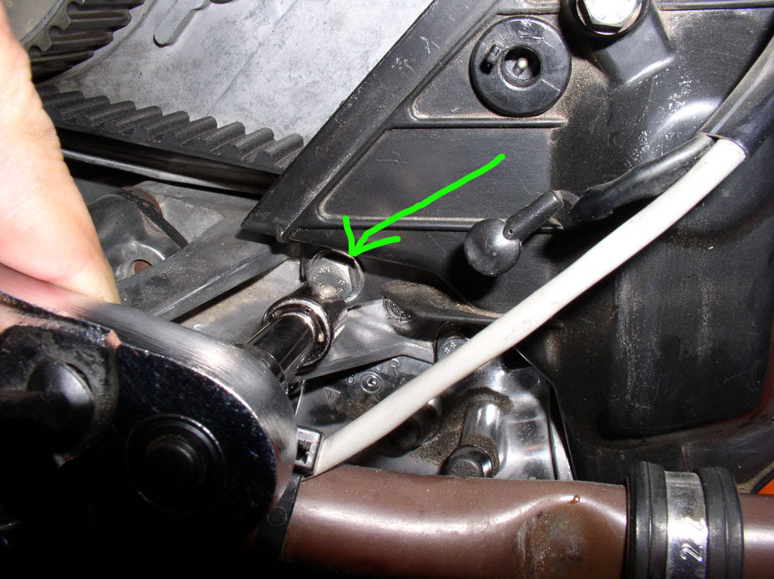
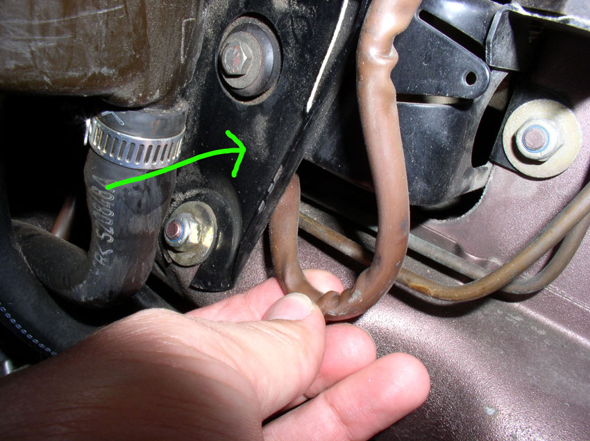
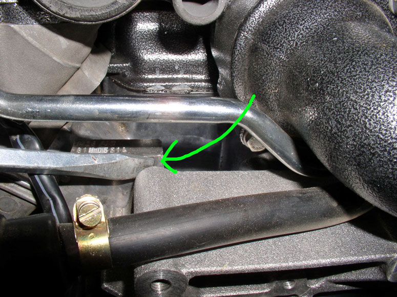
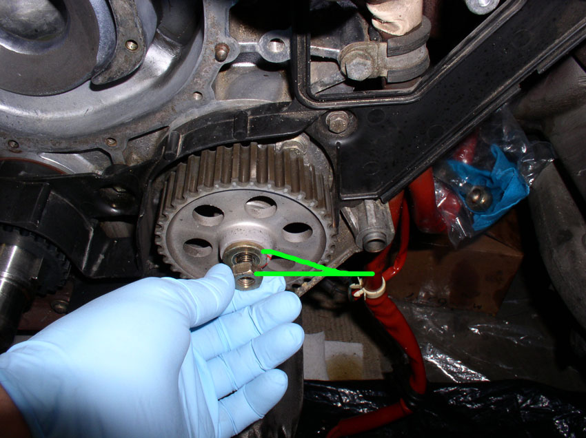
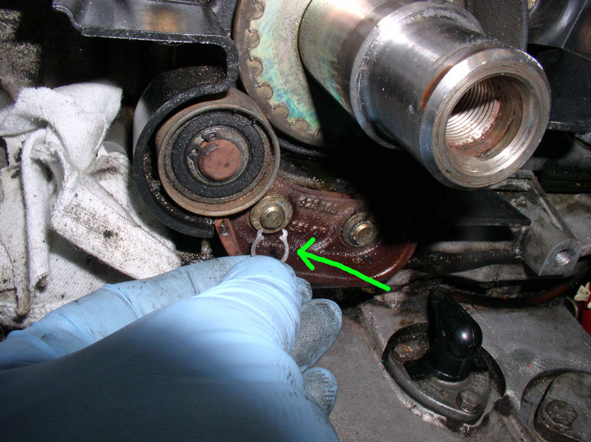
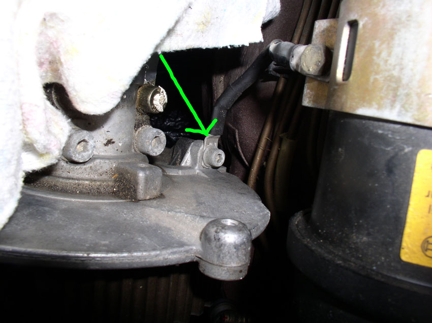
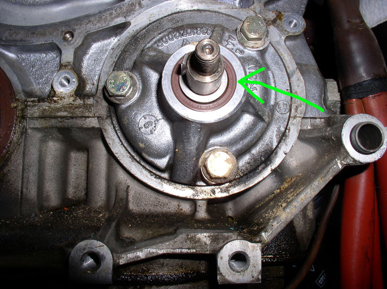
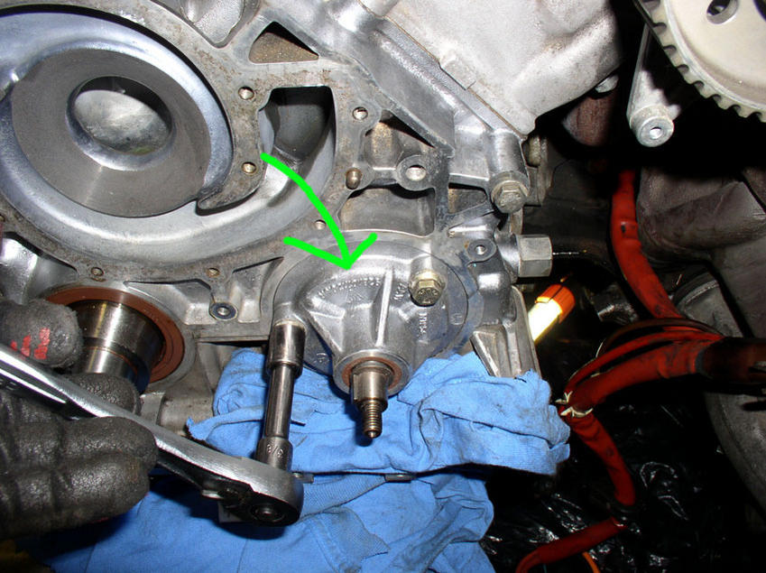
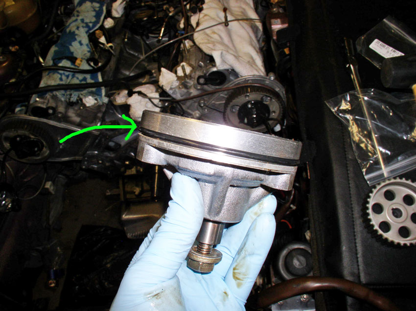
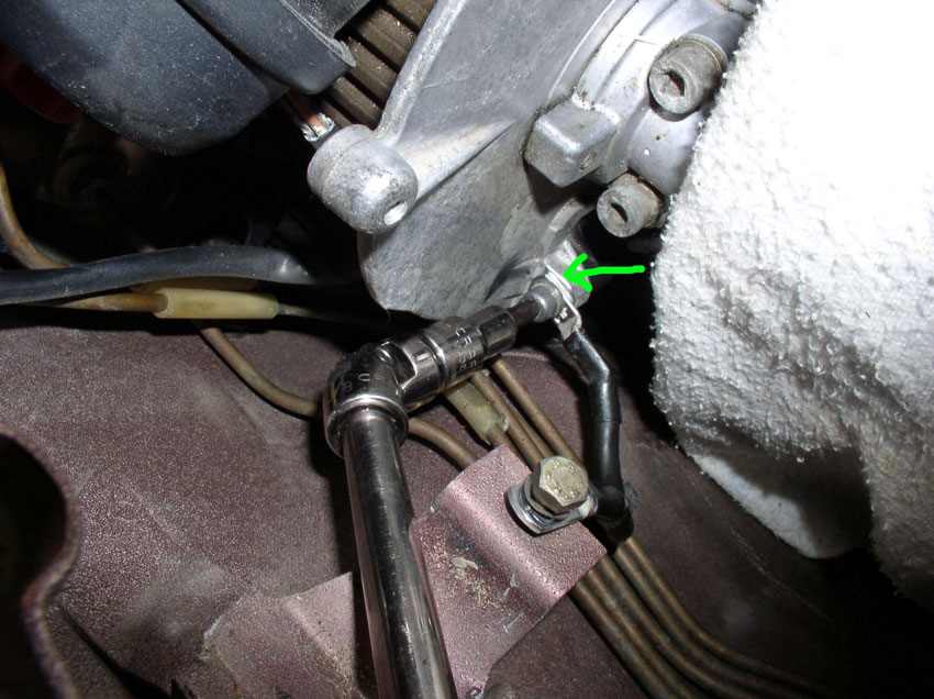
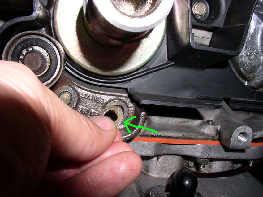
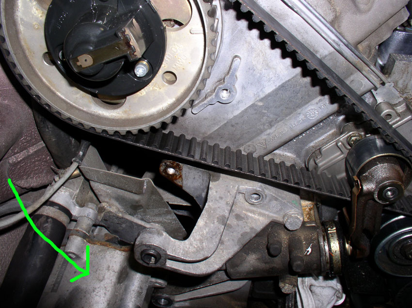
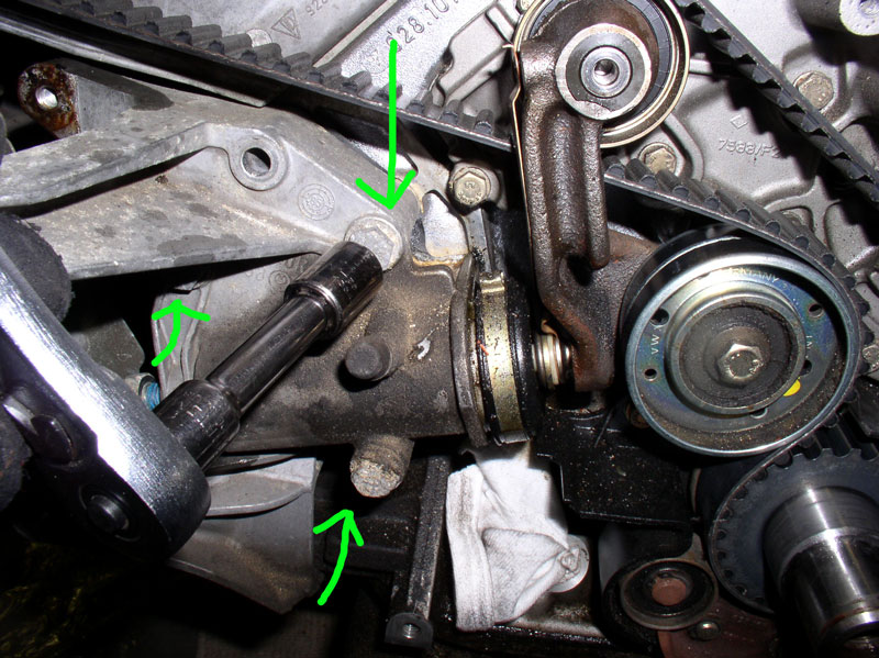
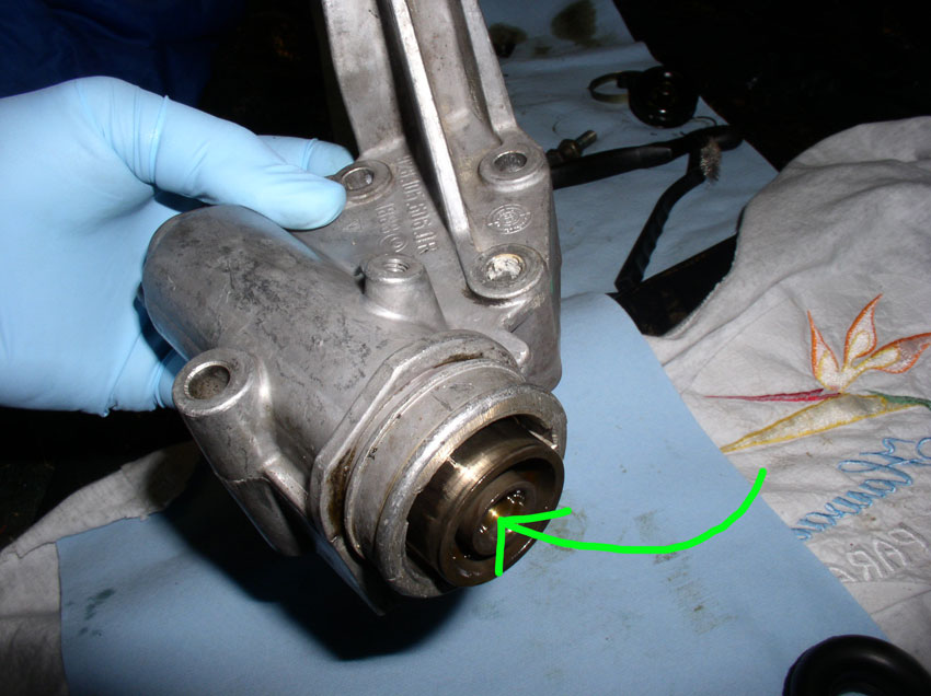
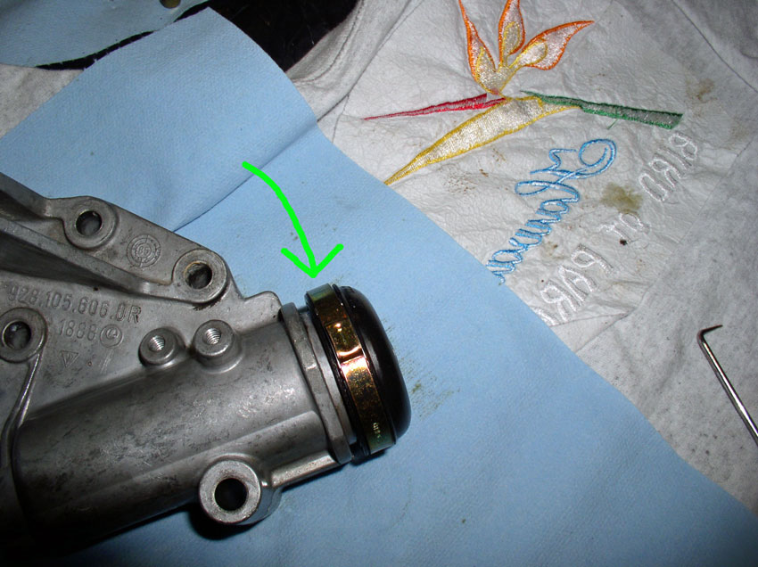
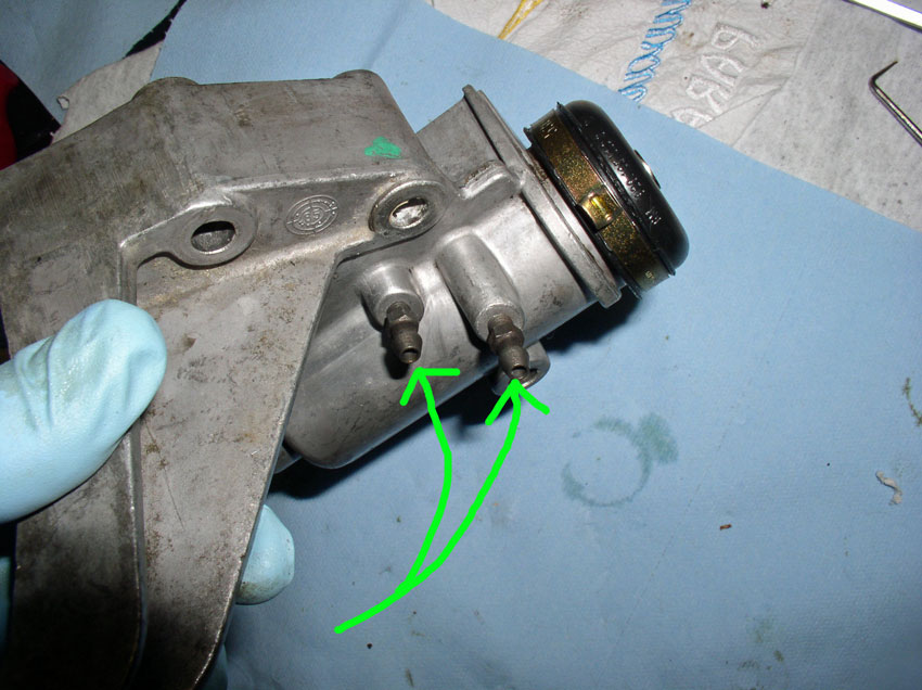
The oil pump has a seal on the spindle as indicated by the green arrow in the pic below. This seal was in very good shape so I left it alone. However, if you wanted to replace it, when the pump is removed, you can remove the gears and spindle and can easily replace the seal with a new one. That procedure is not covered here.
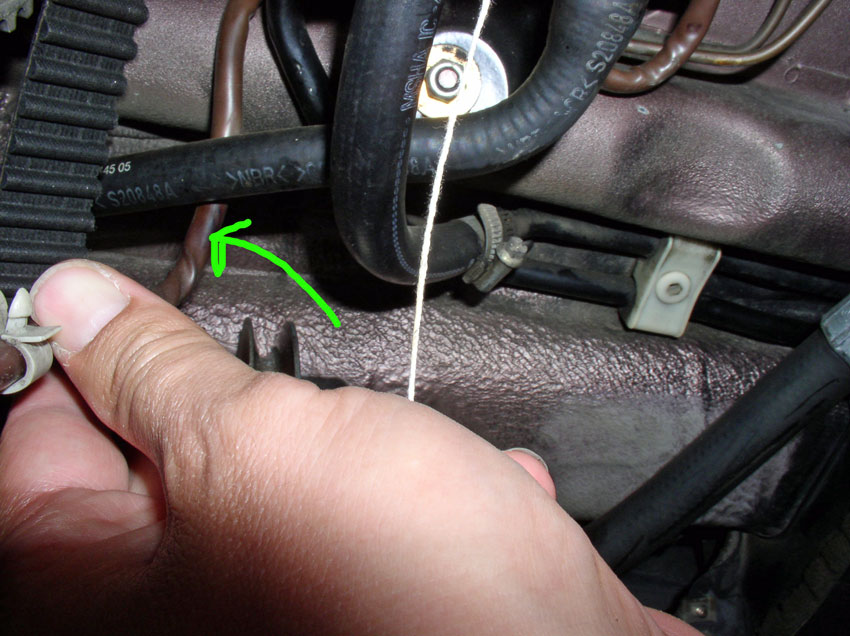
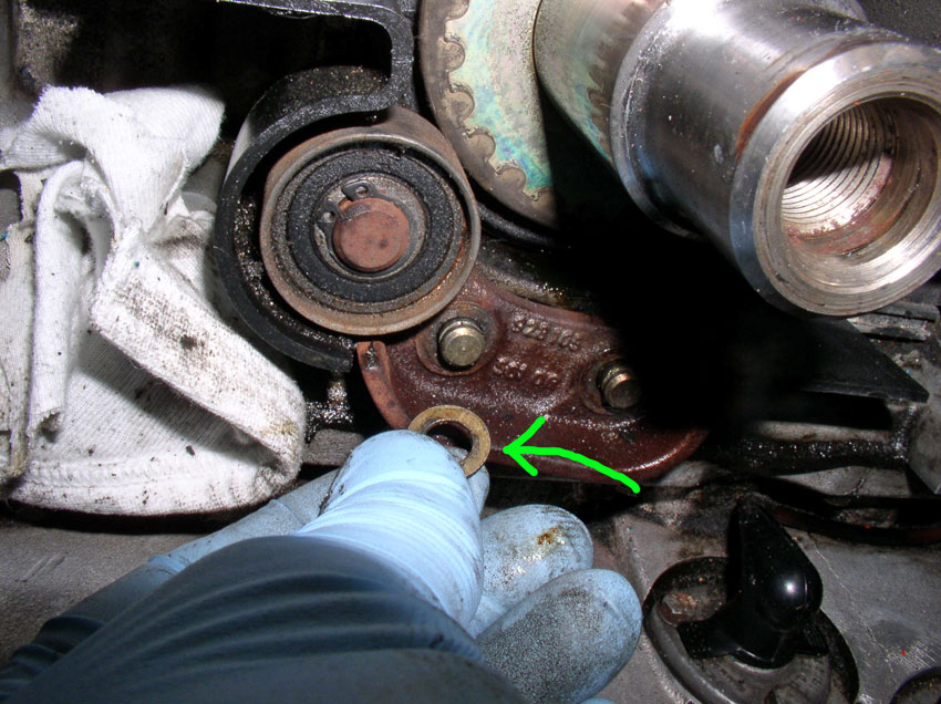
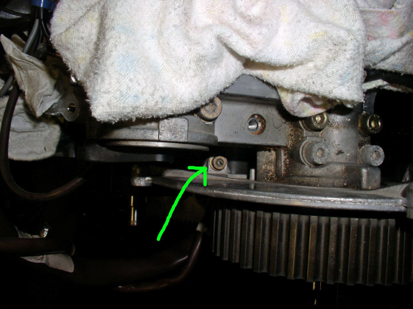
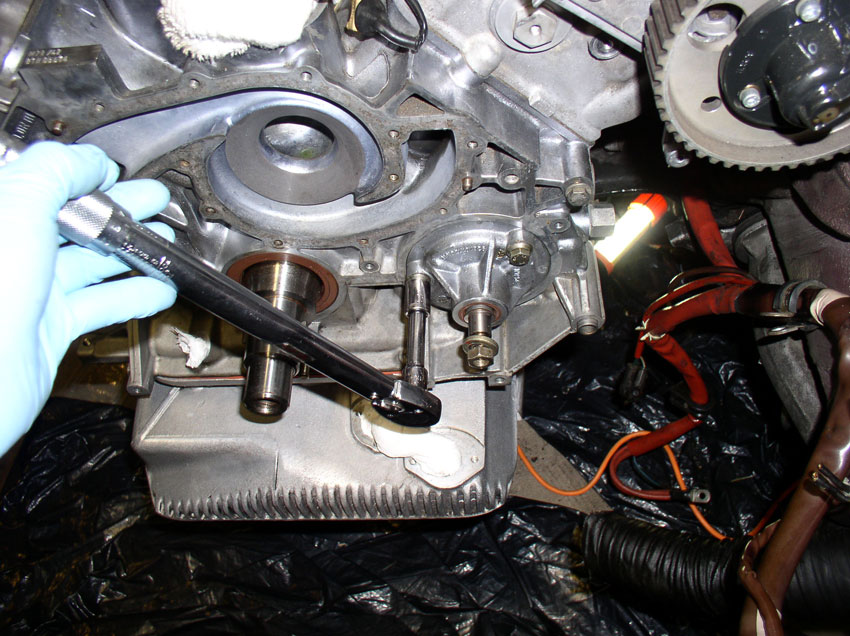
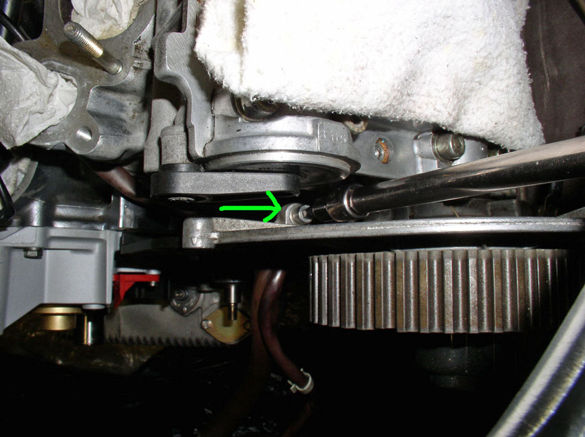
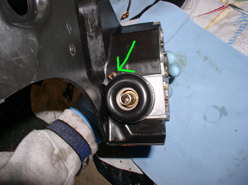
Also, you can inspect the crank shaft front seal for leaks. It appears from this pic below, my seal may be weeping (slight leak). I decided to leave it alone and monitor it for leaking. If you were going to replace seal. Now would be the time to do it. You can see by the green arrow to the left, there is a canal cut into the engine block that will give you access to pry the old seal out. Once the old seal is out, you can press the new one in. However, that procedure is not covered here. I will replace the seal the next time I'm in there.
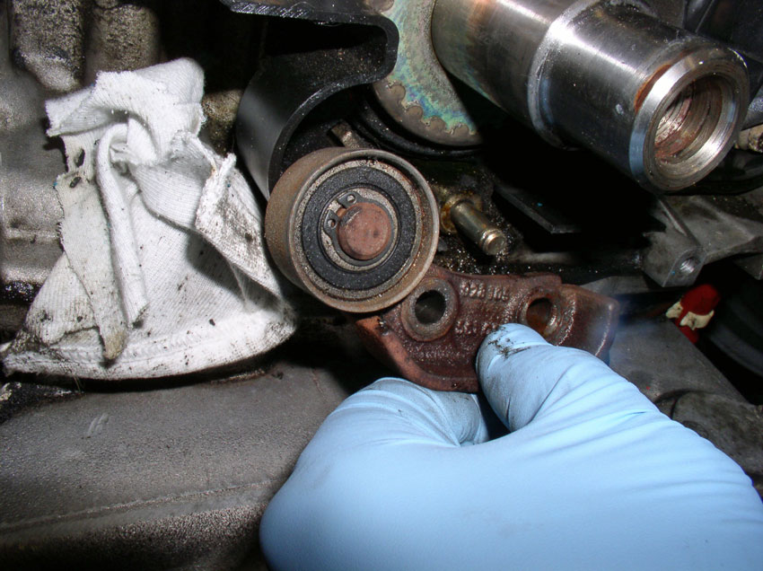
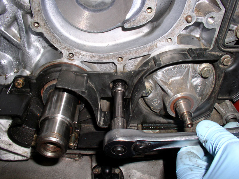
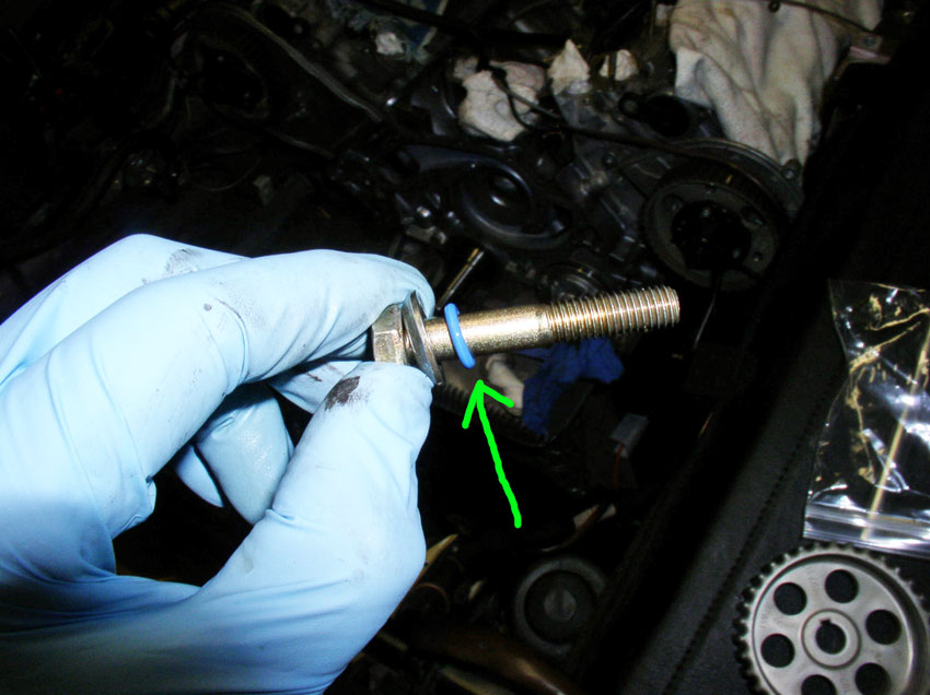
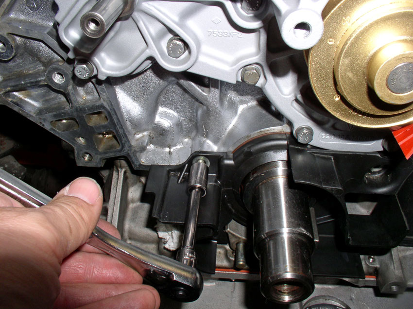
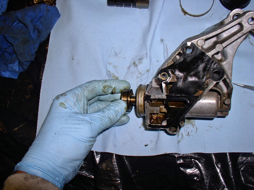
To remove the oil pump, remove the three 13mm bolts that secure the pump to the engine block. Each bolt has an umbrella washer and an o-ring. We'll be replacing the o-rings later.
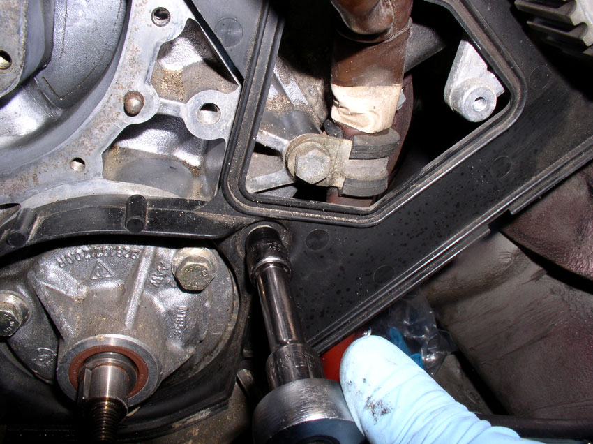
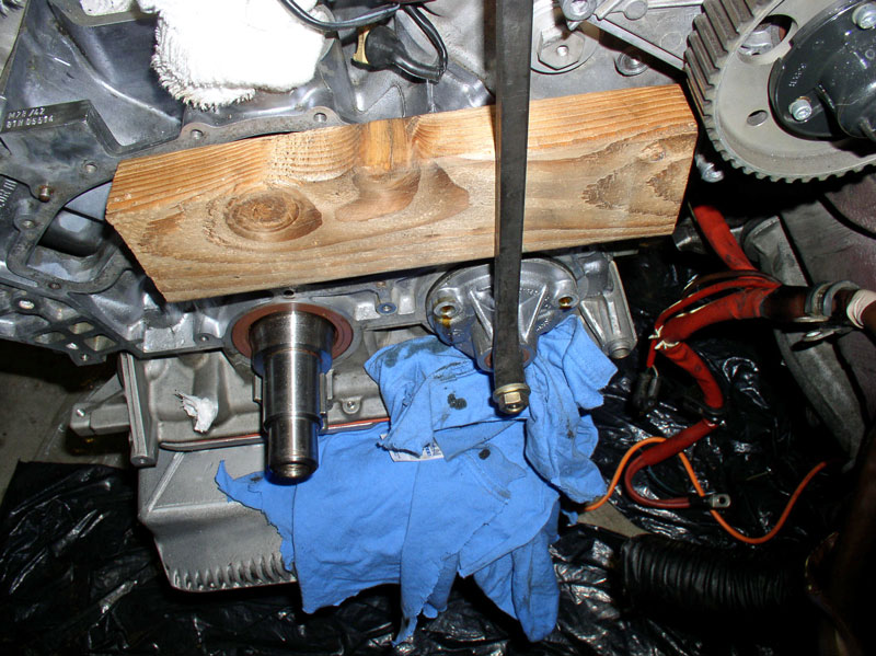
Once you get the bolts out, you will need to pry or pull the pump out. The method that worked well for me was to use a short section of 2X4 and a long pry bar. Put the gear washer and bolt back on the spindle as shown below. Place the 2X4 against the block and use the pry bar to lever against the 2X4 and the washer and bolt to carefully pry the pump out (see below).
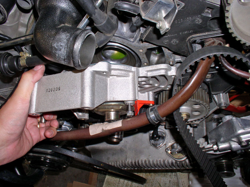
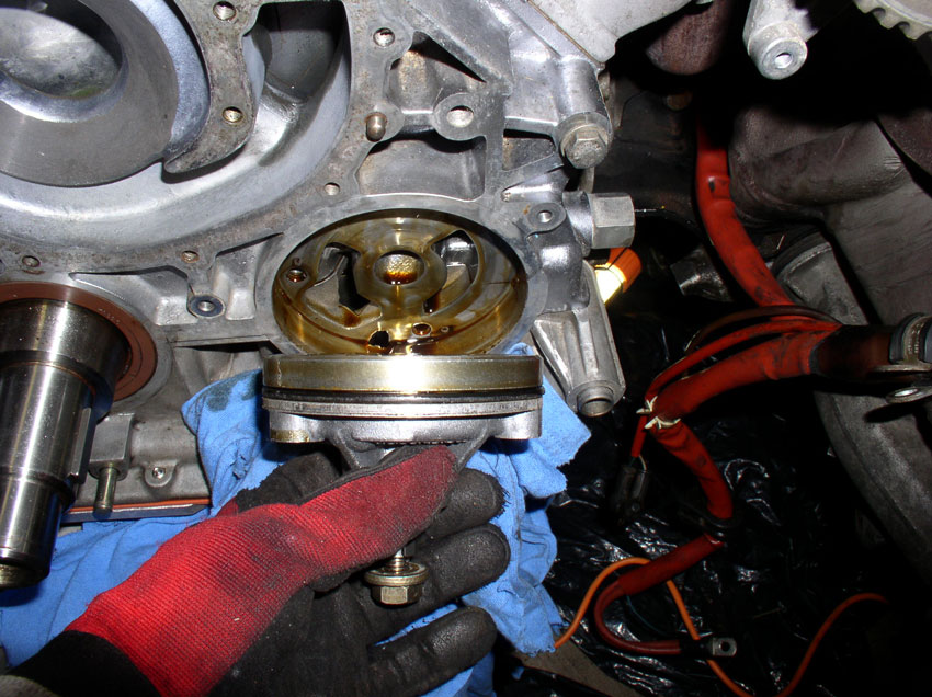
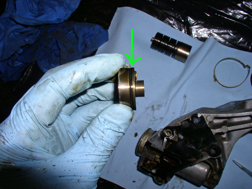
Make note of the oil pump orientation. For example, mine had the part number at the top. Remove the pump as shown.
Use a small screwdriver or pick tool to remove the old oil pump O-Ring as shown.
Install the new O-Ring and coat with some motor oil to help it slide back in on install.
Remove the old O-Rings from the 3 mounting bolts and install the new O-rings one on each bolt.
Place the Oil Pump back into the block in the same orientation as it came out and re-install the three 13mm mounting bolts as shown. The bolts are torqued down in a two step process. First pass, torque down to 11 Ftlbs, on the second pass, torque to 14 Ftlbs.
Continued......
Also, you can inspect the crank shaft front seal for leaks. It appears from this pic below, my seal may be weeping (slight leak). I decided to leave it alone and monitor it for leaking. If you were going to replace seal. Now would be the time to do it. You can see by the green arrow to the left, there is a canal cut into the engine block that will give you access to pry the old seal out. Once the old seal is out, you can press the new one in. However, that procedure is not covered here. I will replace the seal the next time I'm in there.
To remove the oil pump, remove the three 13mm bolts that secure the pump to the engine block. Each bolt has an umbrella washer and an o-ring. We'll be replacing the o-rings later.
Once you get the bolts out, you will need to pry or pull the pump out. The method that worked well for me was to use a short section of 2X4 and a long pry bar. Put the gear washer and bolt back on the spindle as shown below. Place the 2X4 against the block and use the pry bar to lever against the 2X4 and the washer and bolt to carefully pry the pump out (see below).
Make note of the oil pump orientation. For example, mine had the part number at the top. Remove the pump as shown.
Use a small screwdriver or pick tool to remove the old oil pump O-Ring as shown.
Install the new O-Ring and coat with some motor oil to help it slide back in on install.
Remove the old O-Rings from the 3 mounting bolts and install the new O-rings one on each bolt.
Place the Oil Pump back into the block in the same orientation as it came out and re-install the three 13mm mounting bolts as shown. The bolts are torqued down in a two step process. First pass, torque down to 11 Ftlbs, on the second pass, torque to 14 Ftlbs.
Continued......
01-01-2010, 11:33 PM
#26
Three Wheelin'
Thread Starter
Join Date: Sep 2007
Location: Ridgecrest, California
Posts: 1,363
Likes: 0
Received 149 Likes
on
33 Posts
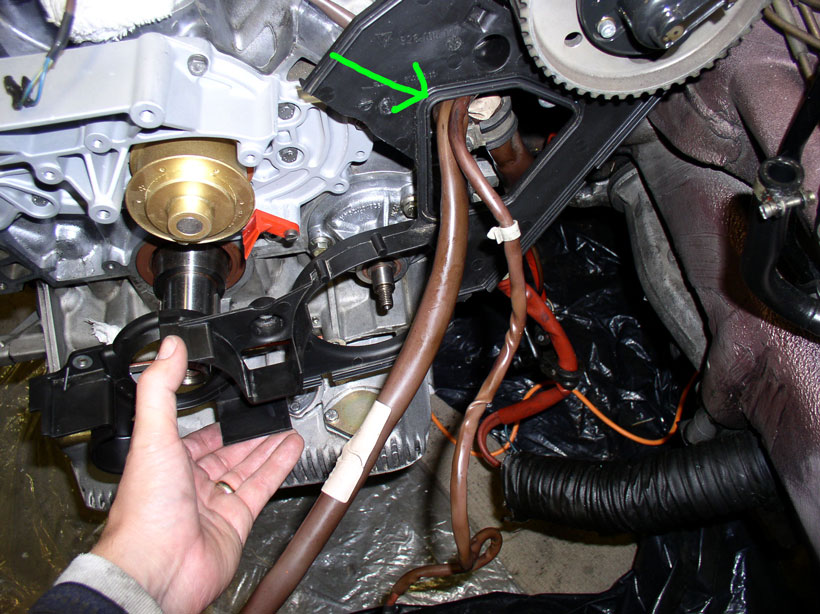
Feed the wiring harnesses through the access hole in the timing belt rear cover and position the cover into place as shown.
Install the 5mm allen head Bolt as shown. Ensure the grounding wire is installed underneath as pictured.
Install the 2nd 5mm allen head bolt as shown.
Install the first of 3 10mm bolts as shown below.
Install the second mounting bolt, 10mm.
And the final 10mm mounting bolt as shown.
Next, install the rear timing belt guide onto the crank shaft as shown.
Followed by the pulley assembly as shown. Mount it on the two pins.
Install the washers.
Install the circlips as shown. If the clips are stretched out, you can carefully clamp them back into shape with a pair of pliers.
Install the timing belt gear onto the crank shaft.
Install the oil pump gear on its shaft as shown.
Install the washer and the gear nut next.
While counterholding the gear, tighten the gear nut to 30 Ftlbs.
Continued.....
01-02-2010, 12:05 AM
#27
Three Wheelin'
Thread Starter
Join Date: Sep 2007
Location: Ridgecrest, California
Posts: 1,363
Likes: 0
Received 149 Likes
on
33 Posts
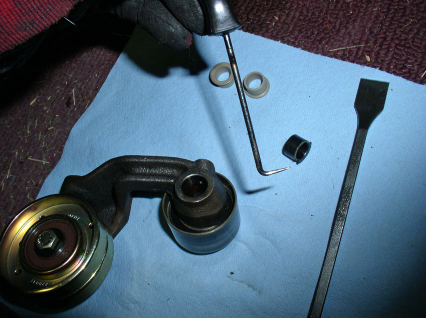
Next, we'll replace the tensioner pulley and bushings.
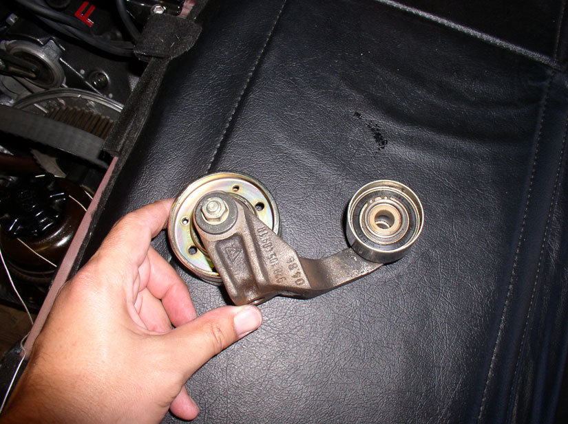
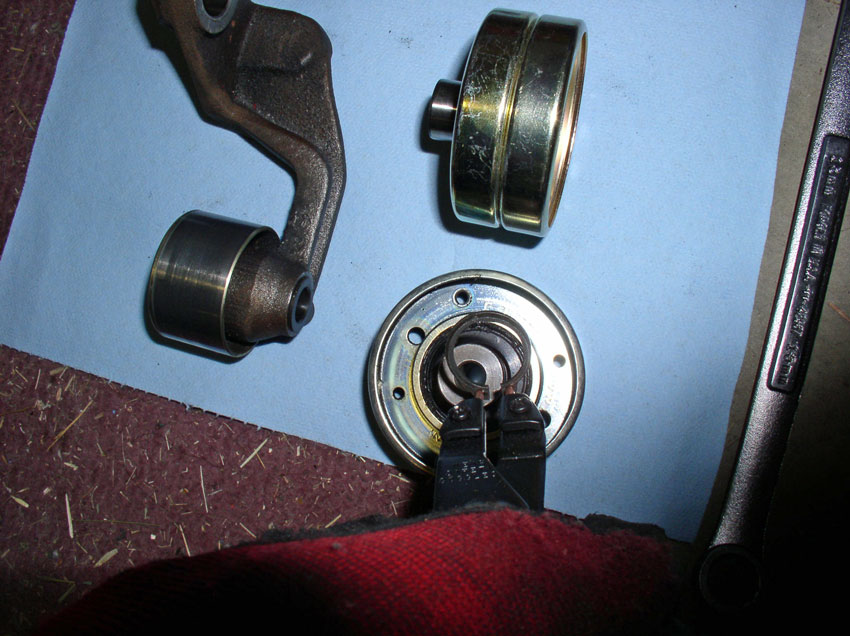
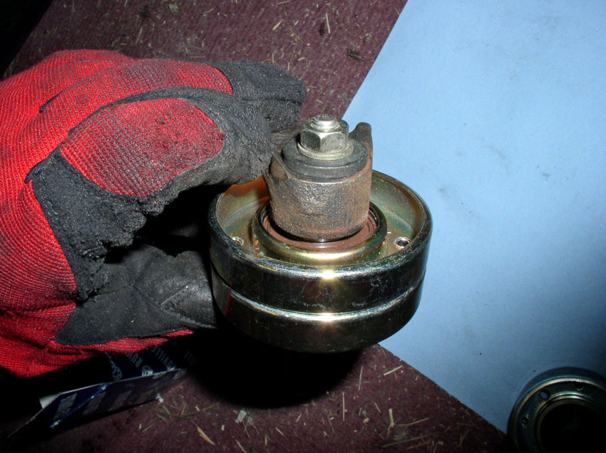
The pulley is mounted to the arm with a 13mm bolt and nut. Counterhold the 13mm nut while loosening the 13mm bolt. Remove the nut and bolt from the pulley and arm assembly
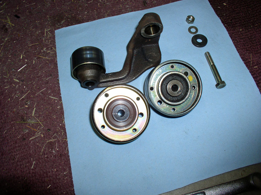
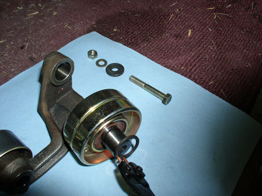
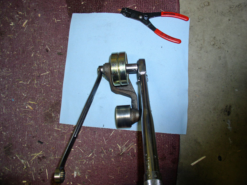
Here's a picture of the disassembled bolt and washers and pulleys (old an new).
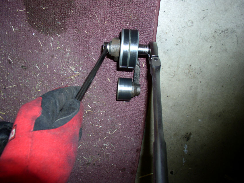
You will need to transfer the large circlip from the old pulley to the new pulley. Use a pair of circlip pliers to remove the clip from the old pulley.
And install in the groove on the new pulley.
Ensure the circlip is fully seated in the groove as pictured.
Install the new pulley into the arm as shown with the circlip facing/contacting the tensioner arm.
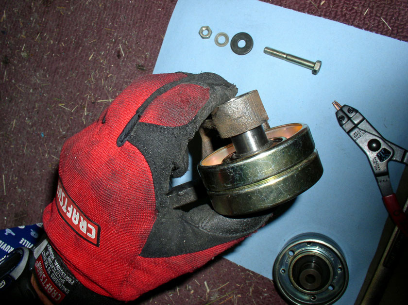
Install the bolt from the front of the pully and install the thick washer first followed by the 2nd washer and finally the nut as pictured.
Counterhold the nut and torgue the bolt to 15 Ftlbs.
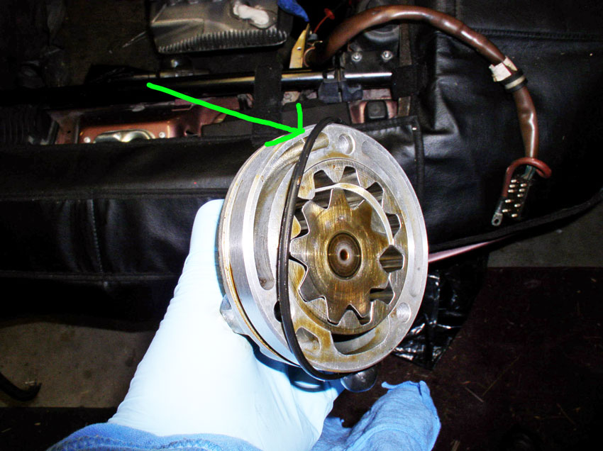
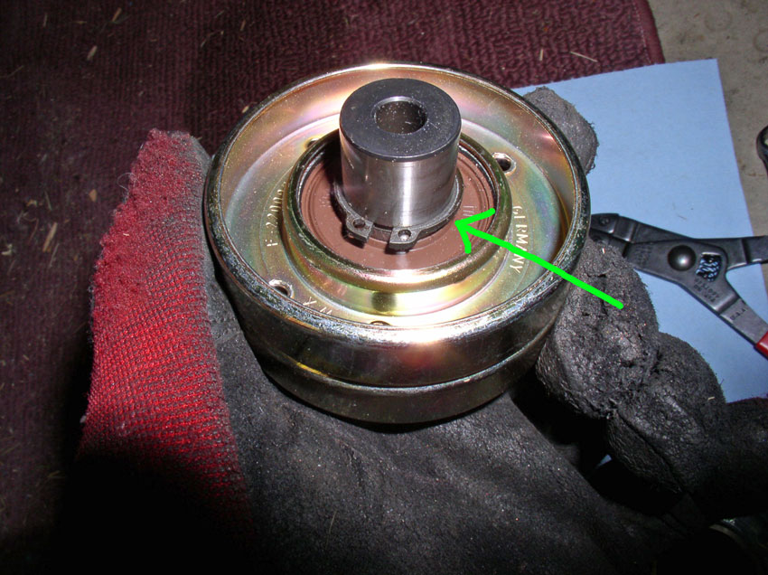
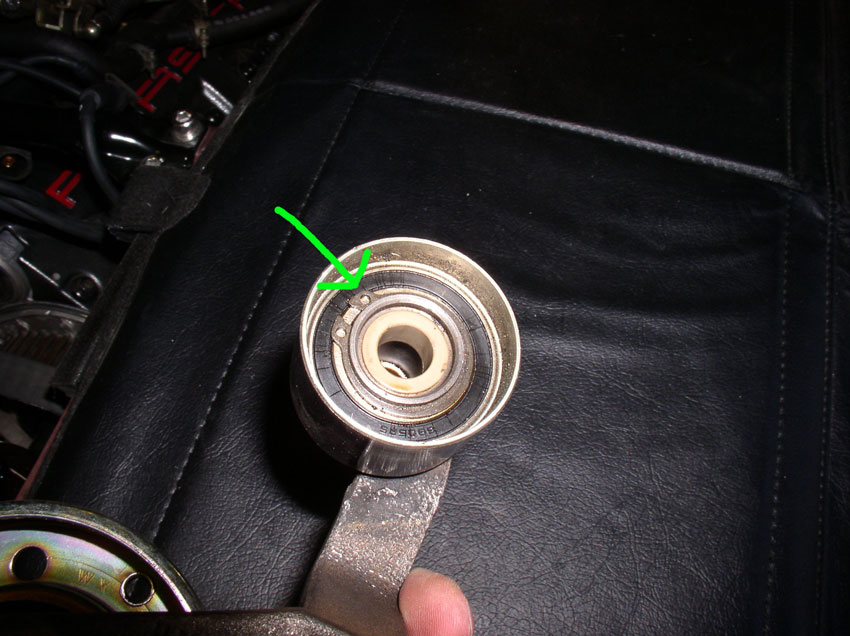
The idler pulley can also be replaced at this time. Mine, however, was still in great shape so I did not replace it. If you are going to replace it, you have to remove this circlip as shown in the picture below. Then separate the pulley from the arm and install the new pulley. The idler pulley helps keep the timing belt from flopping and coming in contact with the pulley mounting hardware since the most slack in the timing belt is in the area of the tensioner pulley. I don't belive the idler pulley is replaced regularly.
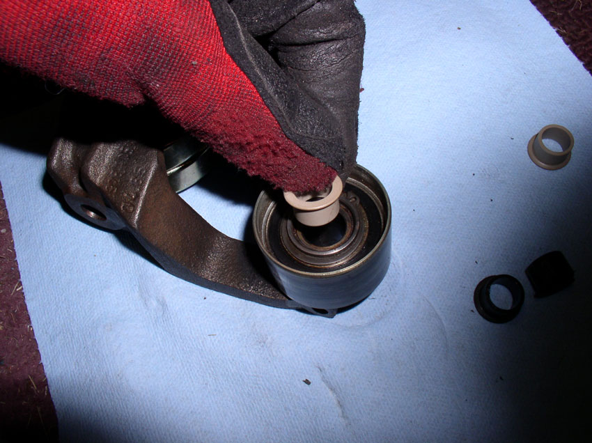
The bushings should be replaced next. To get the old bushings out, I used a pick tool and grabbed the inside edge and pulled up.
It moved a little at a time but eventualy came out. There is a bushing on each side of the pulley. Remove the 2nd bushing as well.
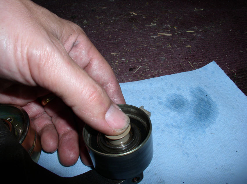
Place the new bushing into the mounting hole.
The bushings are usually a tight fit so you may need to use a "C" clamp to press them in evenly and flush with the mounting bracket. After both bushings are installed the tensioner pulley assembly is ready for installation (later in Chapter 17)
Continued......
The pulley is mounted to the arm with a 13mm bolt and nut. Counterhold the 13mm nut while loosening the 13mm bolt. Remove the nut and bolt from the pulley and arm assembly
Here's a picture of the disassembled bolt and washers and pulleys (old an new).
You will need to transfer the large circlip from the old pulley to the new pulley. Use a pair of circlip pliers to remove the clip from the old pulley.
And install in the groove on the new pulley.
Ensure the circlip is fully seated in the groove as pictured.
Install the new pulley into the arm as shown with the circlip facing/contacting the tensioner arm.
Install the bolt from the front of the pully and install the thick washer first followed by the 2nd washer and finally the nut as pictured.
Counterhold the nut and torgue the bolt to 15 Ftlbs.
The idler pulley can also be replaced at this time. Mine, however, was still in great shape so I did not replace it. If you are going to replace it, you have to remove this circlip as shown in the picture below. Then separate the pulley from the arm and install the new pulley. The idler pulley helps keep the timing belt from flopping and coming in contact with the pulley mounting hardware since the most slack in the timing belt is in the area of the tensioner pulley. I don't belive the idler pulley is replaced regularly.
The bushings should be replaced next. To get the old bushings out, I used a pick tool and grabbed the inside edge and pulled up.
It moved a little at a time but eventualy came out. There is a bushing on each side of the pulley. Remove the 2nd bushing as well.
Place the new bushing into the mounting hole.
The bushings are usually a tight fit so you may need to use a "C" clamp to press them in evenly and flush with the mounting bracket. After both bushings are installed the tensioner pulley assembly is ready for installation (later in Chapter 17)
Continued......
01-02-2010, 12:43 AM
#28
Three Wheelin'
Thread Starter
Join Date: Sep 2007
Location: Ridgecrest, California
Posts: 1,363
Likes: 0
Received 149 Likes
on
33 Posts
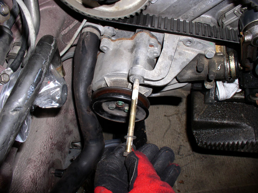
The next sequence of pictures may seem out of order since the timing belt and tensioner pulley are still on the engine but you can ignore those. I had to use an older set of pictures to capture the rebuild process. To remove the timing belt tensioner, you will need to remove the air pump from the tensioner bracket. Loosen and remove the 13mm pivot bolt on the air pump as shown.
Work the air pump back and forth while pushing down and work it out of the bracket. When it comes out, set it aside down below out of the way.
The tensioner is attached to the block with three 13mm bolts. Two are easily visible but the third is to the left and hard to see under the bracket arm. Loosen and remove the mounting bolts.
Here's a shot at the 3rd bolt located under the bracket arm.
When the bolts are removed, you can use a pry bar to lever off the block and the bracket arm as shown to break the tensioner loose. In case there is any fluid left in the reservoir, you may want to place a rag or towel under the tensioner before breaking it loose.
Once loose, remove the tensioner.
You can see the gasket was pretty much shot on this tensioner. The tensioner holds fluid (90w Gear Oil) that helps transfer engine heat and provide lubrication to the tensioner washers inside. When the engine warms up, it expands and causes the tension on the timing belt to increase. The purpose of the tensioner is to provide slack in the timing belt to compensate for the extra tension created by the expanding engine.
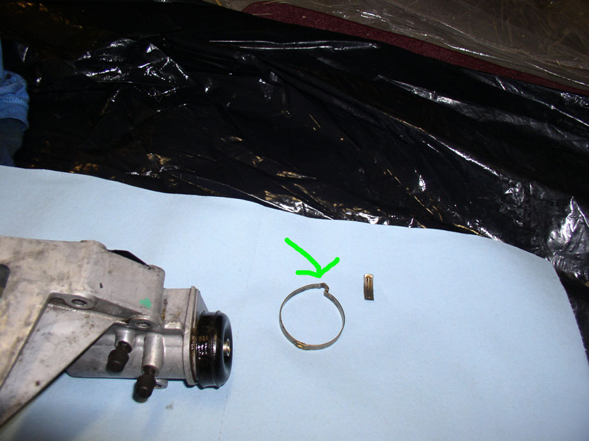
To rebuild/repair the tensioner, first remove the boot clamp. It is easily removed by placing a screwdriver in the crimped part of the clamp and twisting the screwdriver to open the crimp. Once the crimp is opened, the clamp can be removed.
Then remove the boot as shown.
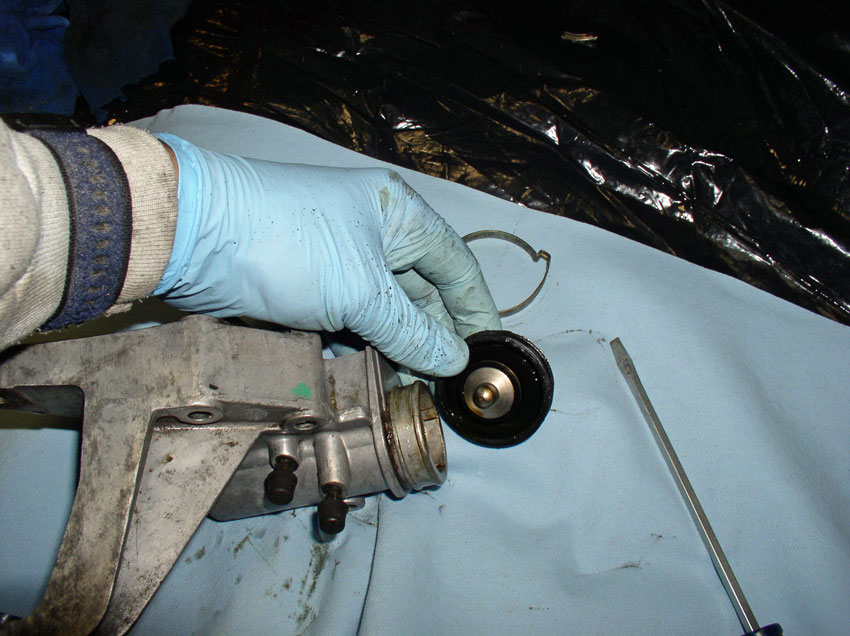
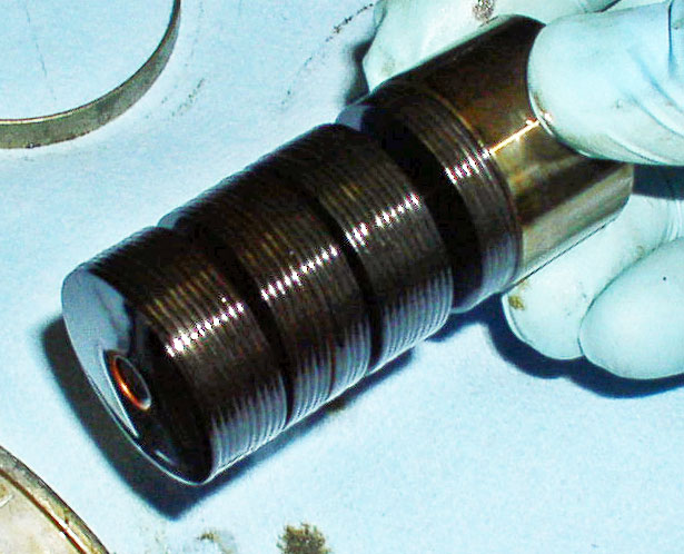
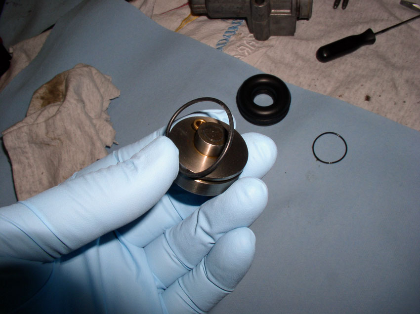
Hold the tensioner facing downward with your hand over the opening to catch the washer assembly. Carefully remove the washer stack and leave the washer stack in tact. There is no need to disassemble the washers unless they are caked and stuck together. If they need to be cleaned you can remove them. There should be a total of 35 washers. They are concave rather than flat. When they heat up, the washers flatten out.
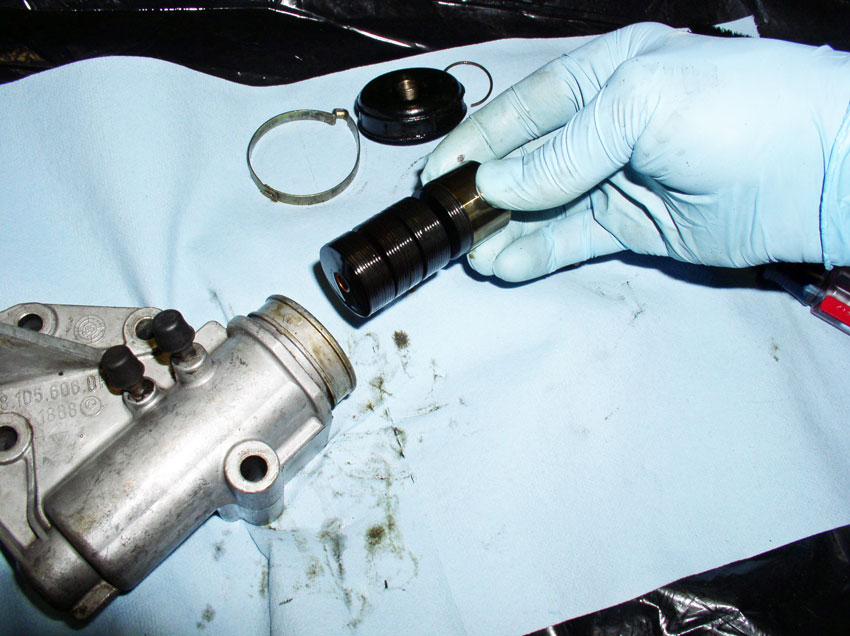
Here's a close up of the washers. They are grouped in sets of 5. If you have to take them apart you will reassemble in the same order they were taken apart. You will have 7 groups of 5 washers each. The 5 washers in each group will be facing the same direction. Each group of 5 washers will be assembled on the spindle in opposing directions and it should look like the pic below.
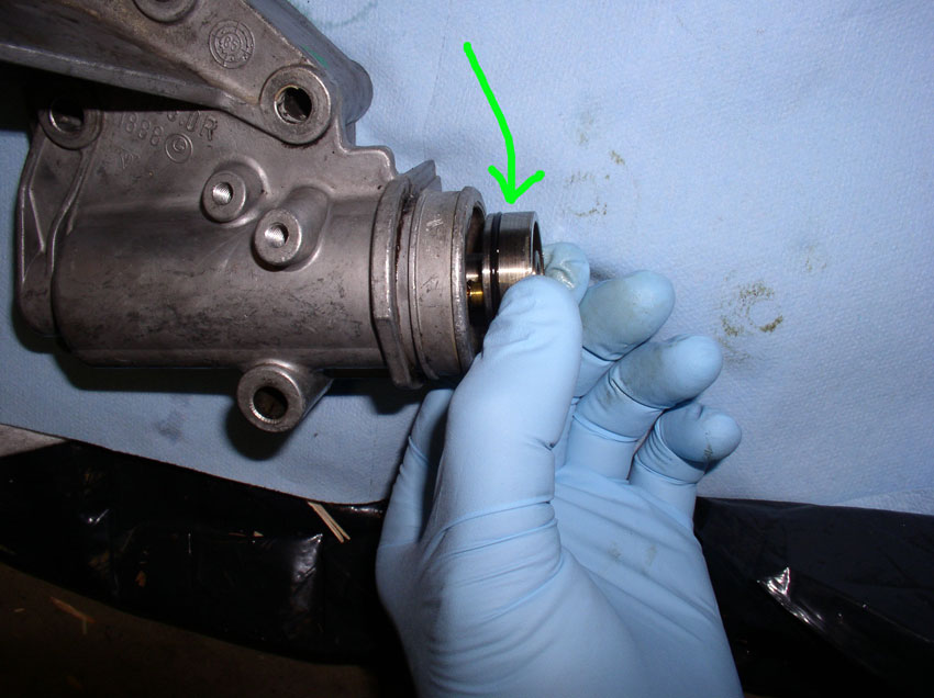
After the washer stack has been removed, you should be able to see the piston at the bottom of the tensioner. This needs to be removed as well because it has an O-Ring that should be replaced.
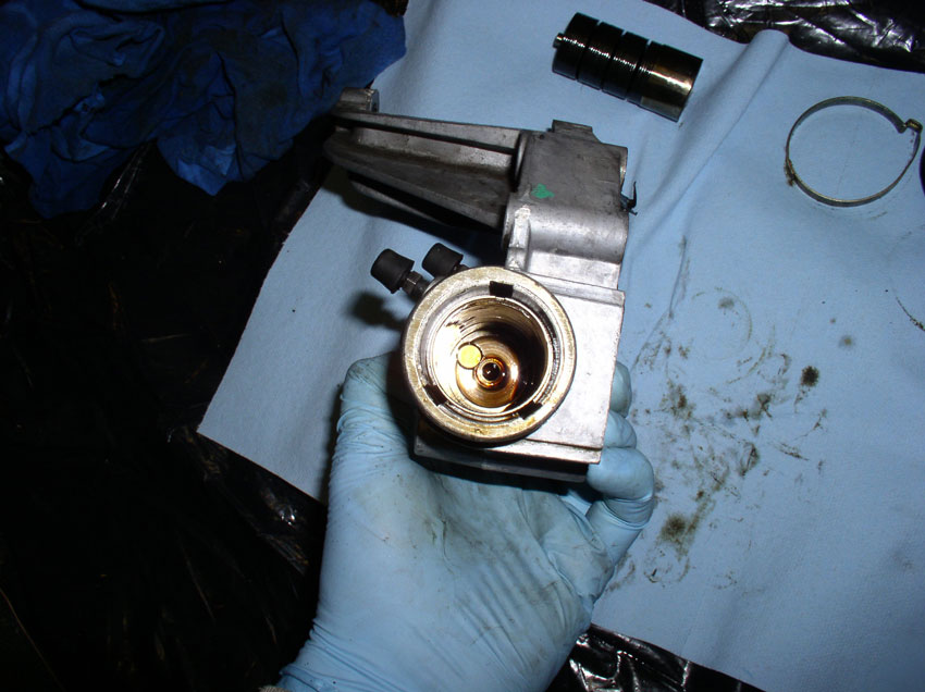
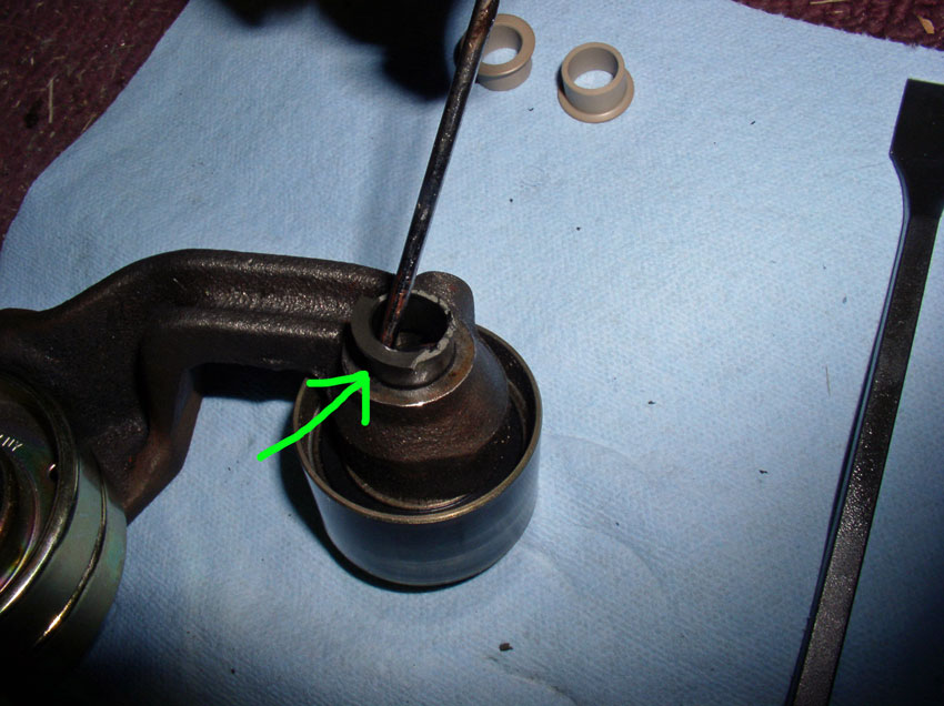
Remove the tension adjusting bolt from the rear of the tensioner housing and insert a punch or screwdriver. You should be able to push or lightly tap the screwdriver to push the piston forward.
Remove the piston from the tensioner housing.
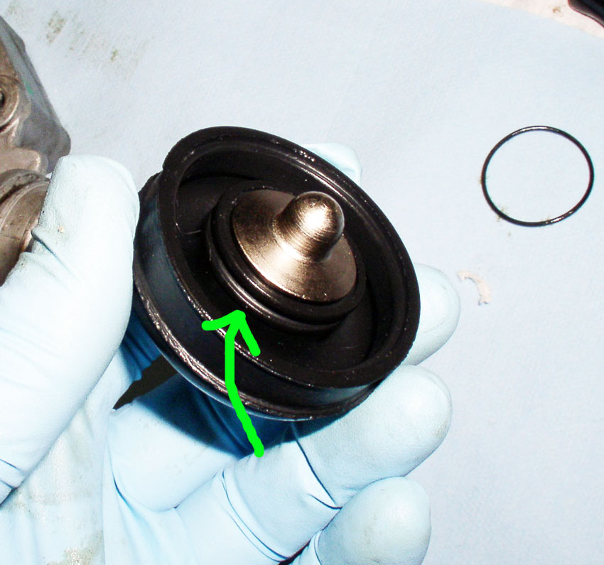
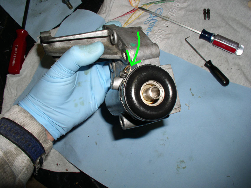
You will need to remove and replace this o-ring indicated by the green arrow in the pic below.
Continued.....
Work the air pump back and forth while pushing down and work it out of the bracket. When it comes out, set it aside down below out of the way.
The tensioner is attached to the block with three 13mm bolts. Two are easily visible but the third is to the left and hard to see under the bracket arm. Loosen and remove the mounting bolts.
Here's a shot at the 3rd bolt located under the bracket arm.
When the bolts are removed, you can use a pry bar to lever off the block and the bracket arm as shown to break the tensioner loose. In case there is any fluid left in the reservoir, you may want to place a rag or towel under the tensioner before breaking it loose.
Once loose, remove the tensioner.
You can see the gasket was pretty much shot on this tensioner. The tensioner holds fluid (90w Gear Oil) that helps transfer engine heat and provide lubrication to the tensioner washers inside. When the engine warms up, it expands and causes the tension on the timing belt to increase. The purpose of the tensioner is to provide slack in the timing belt to compensate for the extra tension created by the expanding engine.
To rebuild/repair the tensioner, first remove the boot clamp. It is easily removed by placing a screwdriver in the crimped part of the clamp and twisting the screwdriver to open the crimp. Once the crimp is opened, the clamp can be removed.
Then remove the boot as shown.
Hold the tensioner facing downward with your hand over the opening to catch the washer assembly. Carefully remove the washer stack and leave the washer stack in tact. There is no need to disassemble the washers unless they are caked and stuck together. If they need to be cleaned you can remove them. There should be a total of 35 washers. They are concave rather than flat. When they heat up, the washers flatten out.
Here's a close up of the washers. They are grouped in sets of 5. If you have to take them apart you will reassemble in the same order they were taken apart. You will have 7 groups of 5 washers each. The 5 washers in each group will be facing the same direction. Each group of 5 washers will be assembled on the spindle in opposing directions and it should look like the pic below.
After the washer stack has been removed, you should be able to see the piston at the bottom of the tensioner. This needs to be removed as well because it has an O-Ring that should be replaced.
Remove the tension adjusting bolt from the rear of the tensioner housing and insert a punch or screwdriver. You should be able to push or lightly tap the screwdriver to push the piston forward.
Remove the piston from the tensioner housing.
You will need to remove and replace this o-ring indicated by the green arrow in the pic below.
Continued.....
01-02-2010, 01:07 AM
#29
Three Wheelin'
Thread Starter
Join Date: Sep 2007
Location: Ridgecrest, California
Posts: 1,363
Likes: 0
Received 149 Likes
on
33 Posts
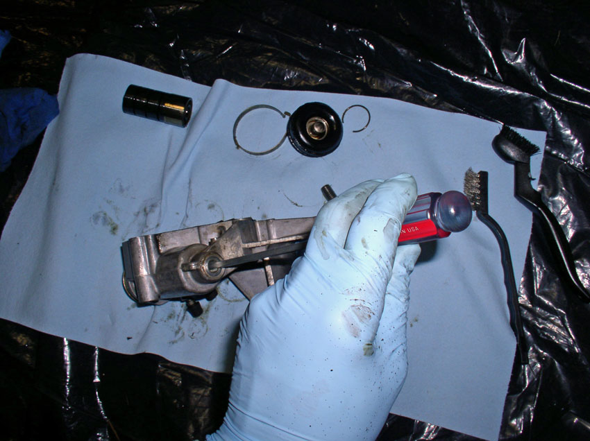
I removed and cleaned the gear oil filler and bleeder fittings next. You will need to clean the housing including the gasket material from the housing at this time.
Now remove the o-ring from the piston using a pick tool
Place the new o-ring on the piston and oil the o-ring so it will install back into the housing without deforming the o-ring.
Install the piston back into the tensioner housing and push the pistion to the bottom.
Next, install the washer stack into the tensioner housing as shown.
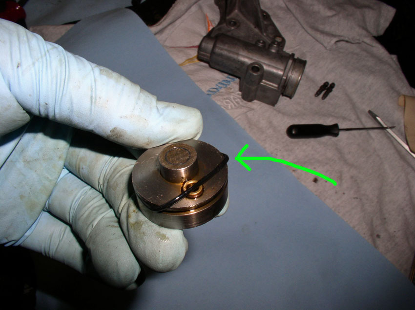
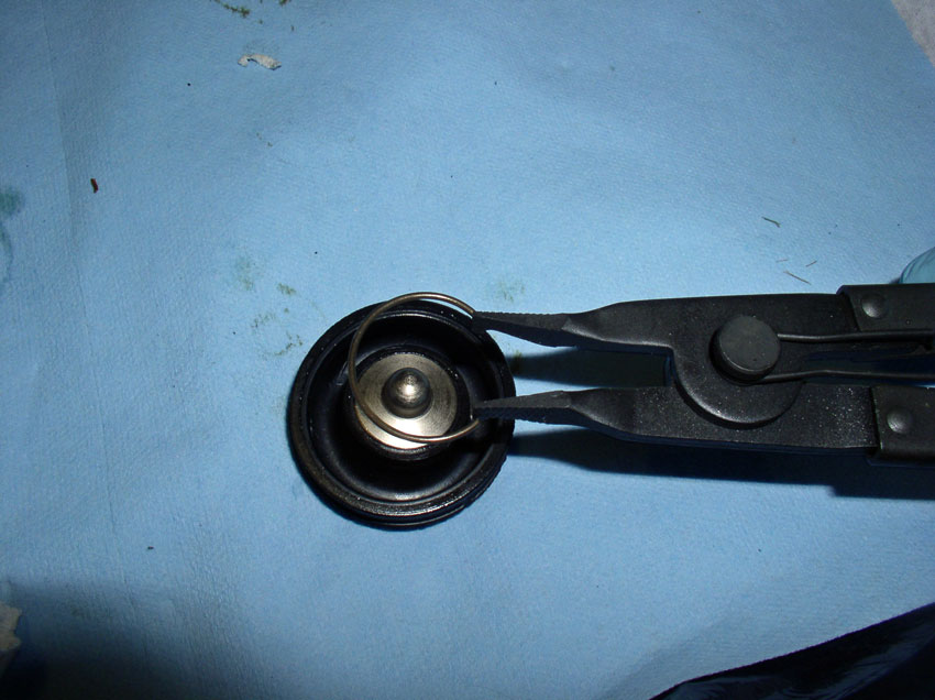
To replace the tensioner boot, you will need to remove the spring clip from the boot.
Use a pair of circlip pliers with flat ends to remove the spring clip.
Once the spring clip is removed. Remove the metal center section from the old boot and transfer it to the new boot. Install the spring on the new boot with the transferred center piece.
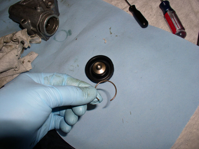
The spring clip should be fully seated in the groove in the boot as shown. Sorry for the fuzzy picture.
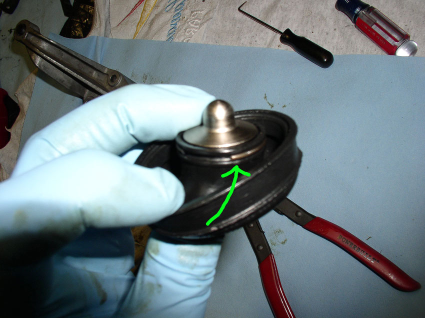
Install the boot onto the front of the tensioner housing. Ensure the boot is fully seated over the "lip" of the tensioner housing. You can see the lip on the housing in the picture below.
Install the new boot clamp on the boot at this time but do not crimp the clamp yet. You will need to make sure the orientation of the crimp does not interfere with the timing belt cover.
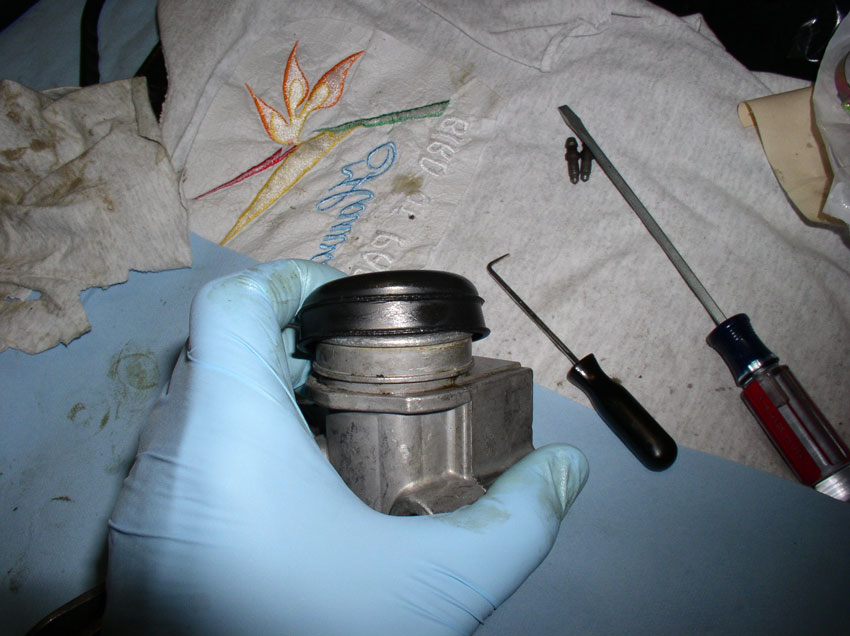
Fit the timing belt center cover over the tensioner as it would when installed on the block.
Then look behind the cover to see how the crimp is oriented to the cover. Orient the crimp so it is not touching the timing belt cover as shown below.
Now you can remove the timing belt cover and crimp the tensioner boot clamp in place.
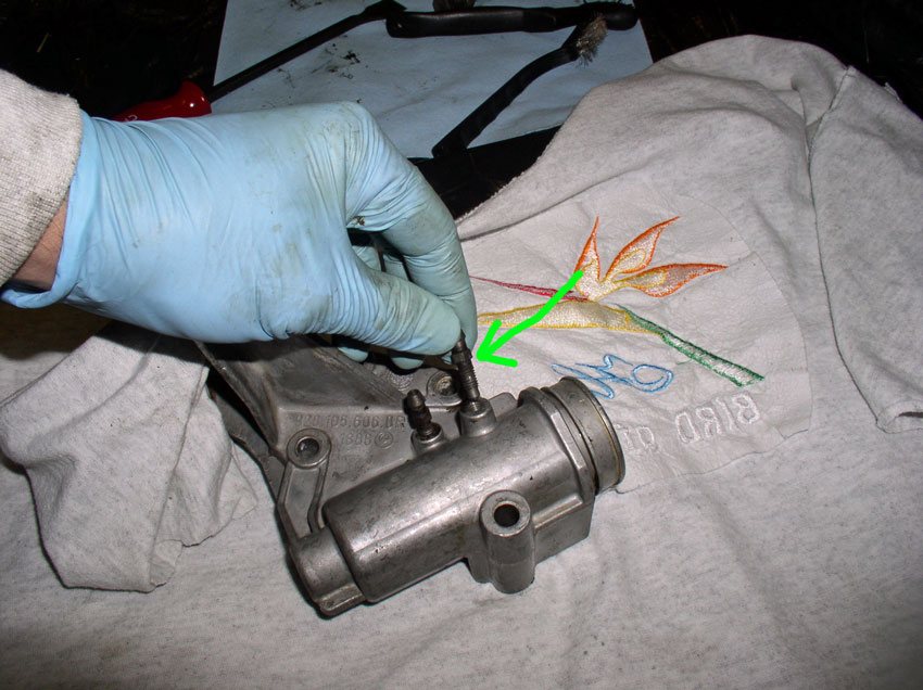
Lastly, re-install the gear oil filler and bleeder fittings.
Installing the water pump is next.
Continued.....
Now remove the o-ring from the piston using a pick tool
Place the new o-ring on the piston and oil the o-ring so it will install back into the housing without deforming the o-ring.
Install the piston back into the tensioner housing and push the pistion to the bottom.
Next, install the washer stack into the tensioner housing as shown.
To replace the tensioner boot, you will need to remove the spring clip from the boot.
Use a pair of circlip pliers with flat ends to remove the spring clip.
Once the spring clip is removed. Remove the metal center section from the old boot and transfer it to the new boot. Install the spring on the new boot with the transferred center piece.
The spring clip should be fully seated in the groove in the boot as shown. Sorry for the fuzzy picture.
Install the boot onto the front of the tensioner housing. Ensure the boot is fully seated over the "lip" of the tensioner housing. You can see the lip on the housing in the picture below.
Install the new boot clamp on the boot at this time but do not crimp the clamp yet. You will need to make sure the orientation of the crimp does not interfere with the timing belt cover.
Fit the timing belt center cover over the tensioner as it would when installed on the block.
Then look behind the cover to see how the crimp is oriented to the cover. Orient the crimp so it is not touching the timing belt cover as shown below.
Now you can remove the timing belt cover and crimp the tensioner boot clamp in place.
Lastly, re-install the gear oil filler and bleeder fittings.
Installing the water pump is next.
Continued.....
01-02-2010, 06:21 AM
#30
Drifting
Fantastic stuff Dwayne. Thank you. This job not scheduled for another year or two on my car but am really looking forward to it with such lucid and thorough instructions.
Have done early parts of this procedure several times for other projects (such as retension, ancillary belt replacement, refurb PS pump) but still found tips and advice I hadn't come across or thought of.
Have read other threads on TB replacement where people have struggled with pulleys/harmonic balancer, and you just calmly use a puller having replaced centre bolts.