
New 4 V head flow figures
 12-06-2009, 04:41 PM
#46
Former Sponsor

That's a great point and invites more thought. This was such an issue with the CIS injected 911 engines that Porsche designed a specially shaped piston to remix the fuel and the air, after it left the port. It is interesting that the 928 piston has none of the characteristics that would help with this re-mixing.
When those valves open, with that fuel "running" down the port walls, the fuel must just "dribble" off of the short wall radius and valve seat. No wonder that part of the port is always "washed", while the balance of the port has carbon.
 12-06-2009, 05:04 PM
#47
Nordschleife Master
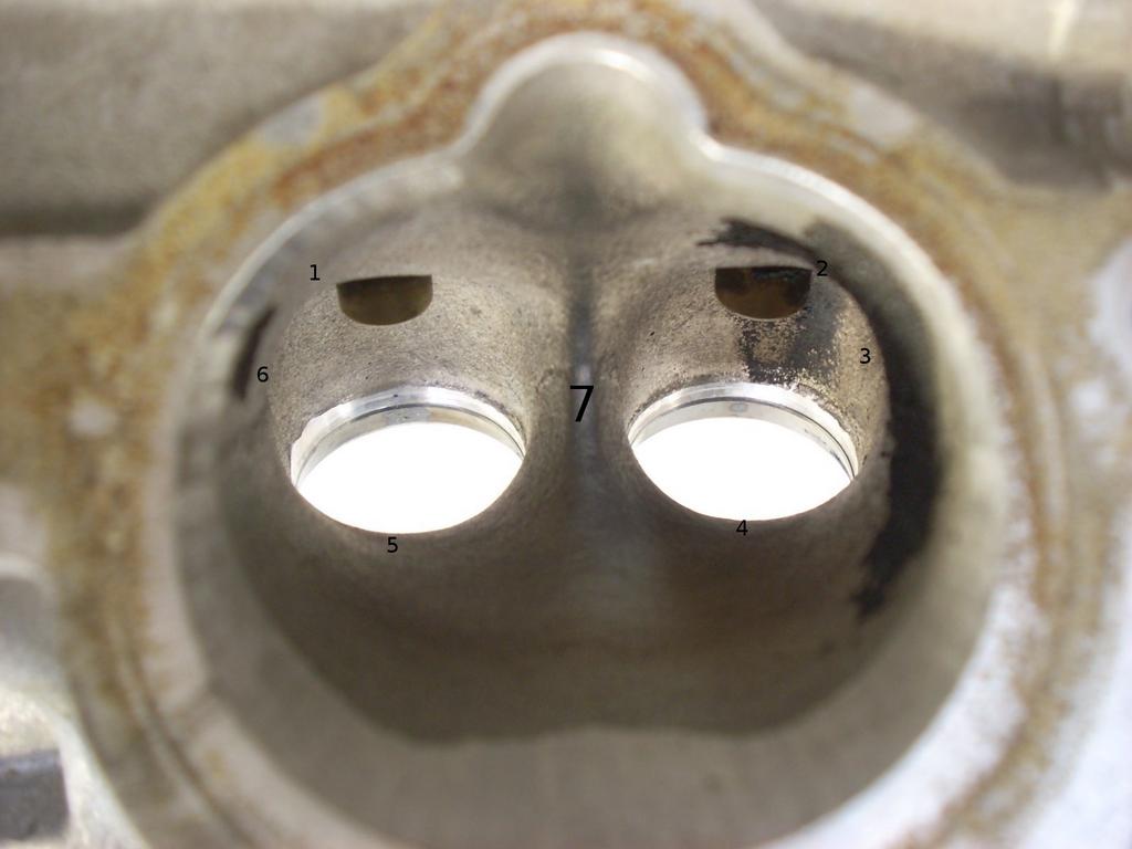
If you look at any late 928 engine, with the intake manifold off, it is pretty clear (from the areas that get carboned up and from the areas that get "fuel washed") that the fuel flows down the shortwall, then "runs" past the "valve divider" wall, and is still very poorly mixed as it turns the corner and flows through the valves.
Flowing these heads and studying the port velocities and flow characteristics confirmed that there are significant "dead areas" in the stock port design...especially on the short wall, where the fuel is sprayed. The air flow is really "confused" right there and actually has quite a bit of trouble "deciding" which valve to go through. Port velocities get low and the fuel literally "runs" down that wall and through the valves. My work has been to make the air flow more uniform through the port and remove the significant dead areas that plague the air flow. This allows the fuel to mix much better with the air, resulting in much more uniform "charges."
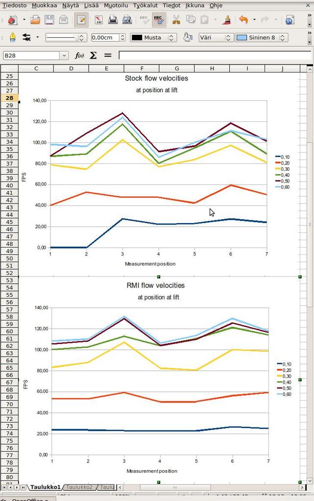
Uniform flow velocities have benefits beyond fuel mixture quality, too.
Welding more material to the bottom of the port floor would further help, but that's expensive.
12-06-2009, 07:55 PM
#48
Nordschleife Master
What Sterling wrote about it being a batch fire system is relevant.
In a batch fire system, there has to be enough runner length before the injector that any sort of reversal in the intake runner can't take the charge out to the plenum. I believe Sterling's plan is to move the injectors further upstream to improve fuel mixture quality. This might not be a good idea with the stock computer, but probably is a good idea with his standalone computer.
Anybody know what's the optimal spray pattern for a batch-fire, single injector per two valves setup?
12-06-2009, 09:44 PM
#50
Addict
Rennlist Member
Rennlist Member
Join Date: Feb 2004
Location: Monterey Peninsula, CA
Posts: 2,374
Likes: 0
Received 16 Likes
on
12 Posts
I asked some engineers that work on the LMP cars, and they mentioned most injectors spray at about 14 Degrees.
In my design of the intake runner/injector block for my application, I took this into consideration, and plan to use 2 injectors per cylinder, and have them a bit more upstream running the Motec to get around many of the issues you guys are raising here. I think as well, that as the LH is batch fire, it convolutes many things, that can be better done with a stand alone ECU.
On the point of fuel atomization, I also believe that there are significant merits to better fuel atomization, and charge homogeniety than has been discussed. The point Greg B made about his strokers getting better mileage points to this as well.
I think that there can be more efficiency brought out form the 928 motor by some better pistons that will improve the BSFC of the motor. There are some Honda guys getting 137% VE, and the head patterns are similar to the 928. I don't see why similar numbers are not possible, and why a BSFC of .39 is not attainable..
Greg G, the Bosch/Ford Motorsport EV6 style injectors have 4 spray holes, and much better atomization than the stock EV1 type that are used on 928 32V motors... They can be had for about $300 a set of 8 in case you have difficulty with the motorcycle injectors.. (I'm not sure if you're using the LH which can only use high impedance, or another ECU which can use low impedance injectors. The Bosch/Ford MS injectors are high impedance..)
The holy grail of course would be to adapt direct injection to the heads with pistons designed to push the charge towards the exhaust valve with a BSFC of 0.34...
Just my $0.02.....
12-07-2009, 12:31 PM
#51
Nordschleife Master
If the inadequately atomized fuel makes it to the combustion chamber and doesn't burn properly, then it may be blown out in the exhaust and now we have a steady-state power problem that requires overfueling. This is an emissions problem also, which isn't getting any better with overfueling.
Another thing that people don't usually think about is that depending on how you spray the fuel into the port, it may slow down the air column. You can spray the fuel as wide, dispersed cone which will help atomization but will slow down the charge and reduce power. Alternatively, you can spray the fuel as fast, narrow cone, which will not slow down the charge but leads to poor atomization.
This is where the race car and street car diverge a bit. For a race car, the most important thing is to get the fuel to the combustion chamber without slowing down the air. For a street car, the most important thing is to atomize the fuel as well as possible. Often, there are constraints that force one to choose one or the other.
My guess is that the best of all worlds is achieved by running a straight intake port+runner, placing the injector high upstream, spraying with a fast narrow cone, and using a precisely timed sequential injection.
12-07-2009, 01:05 PM
#52

Most new injectors, such as those you get from RC engineering - have the multiple holes. I believe it is considered the "disk" type injector. They work great, but there are some draw backs compared to the pintle type:
http://www.sae.org/technical/papers/960116
http://www.sae.org/technical/papers/960116
12-07-2009, 01:18 PM
#53
Additionally, the cycle goes near bank fire spray times over a certain rpm anyway, as the injector starts to have to spray at the back of a closed valve.
*****
My personal issues have to do with injector size. Size does affect atomization. Originally, I was going to move the injector up the runner, but I found that it simply does not test well below 4k rpm or even higher. The reason for this injector size discussion in my project is that ethanol needs an injector about 50% larger than for petrol. Maybe even bigger if I wish to use sequential correctly and have an injector never have a duty cycle past 65%. That, judging from what the normal fuel calculations bring me, leaves me with a 120 or 160lb injector. As I mentioned to Greg B. one time - its like flushing a toilet down the port when that thing opens. I need REALLY GOOD atomization. I need a REALLY GOOD spray patter to make this work. Sequential is my only choice at this injector size.
Coming full circle, the discussion in this thread about what happens in these 928 ports with poorly atomized fuel is scary. Adding larger pintle-type injectors is just probably exacerbating the problem. My heads are done and attached - for this motor. I left them as cast because I felt that the only real improvements I could make were at the bowl area and just past the valve seat - just simple casting flaw removal. And thats all I did. I left the port wall rough because I already knew I would want as much help with wall-wetting as I could get. But again my needs shift somewhat from the this thread because the ethanol's rvp and the way it deals with the heated port is quite different.
So, great discussion. Back to the top - I am hoping the disk type injector help me with spray patter and atomization.
12-07-2009, 01:20 PM
#54
12-07-2009, 01:48 PM
#55
Former Sponsor
Sequential injection does yield power - but only about 5% over bank fire injection. And only when the injectors are sized to be only at about 70% duty cycle or below. (c. A. Graham Bell, "4 Stroke performance tuning")
Additionally, the cycle goes near bank fire spray times over a certain rpm anyway, as the injector starts to have to spray at the back of a closed valve.
*****
My personal issues have to do with injector size. Size does affect atomization. Originally, I was going to move the injector up the runner, but I found that it simply does not test well below 4k rpm or even higher. The reason for this injector size discussion in my project is that ethanol needs an injector about 50% larger than for petrol. Maybe even bigger if I wish to use sequential correctly and have an injector never have a duty cycle past 65%. That, judging from what the normal fuel calculations bring me, leaves me with a 120 or 160lb injector. As I mentioned to Greg B. one time - its like flushing a toilet down the port when that thing opens. I need REALLY GOOD atomization. I need a REALLY GOOD spray patter to make this work. Sequential is my only choice at this injector size.
Coming full circle, the discussion in this thread about what happens in these 928 ports with poorly atomized fuel is scary. Adding larger pintle-type injectors is just probably exacerbating the problem. My heads are done and attached - for this motor. I left them as cast because I felt that the only real improvements I could make were at the bowl area and just past the valve seat - just simple casting flaw removal. And thats all I did. I left the port wall rough because I already knew I would want as much help with wall-wetting as I could get. But again my needs shift somewhat from the this thread because the ethanol's rvp and the way it deals with the heated port is quite different.
So, great discussion. Back to the top - I am hoping the disk type injector help me with spray patter and atomization.
gb
12-07-2009, 02:07 PM
#56
Former Sponsor
The only salvation has to be that the events happen so quickly that the fuel doesn't get much time to "lurk".
12-07-2009, 02:08 PM
#57

Thanks
12-07-2009, 02:24 PM
#58
Nordschleife Master
The packaging of motorcycle engines typically prevents a nice, completely straight, dump runner+port. Furthermore, a consistent throttle response is very important with bikes. That's why they use electroncially controlled second throttles etc.
Some highly tuned street bikes have deal with all these problems listed in this thread with two injectors per port (and two valves). The first injector is right at the port, spraying well-atomize wide cone. The second injector is spraying into the intake runner trumpet, spraying a high-velocity narrow cone. At low fuel demand, only the port injector works. At high fuel demand, either only the trumpet injector works or both injectors work, depending on the system. This allows the port injector to have a high duty cycle corresponding to low fuel flow rate, and thus good atomization.
I belive that this combination gets the best of all worlds in the case of less-than-perfectly straight port-and-runner.
12-07-2009, 02:28 PM
#59
Nordschleife Master
Well, you did suggest the 2 injector idea - which may have worked, but the design on the flanges is now complete - and I get one hole - do its not going to happen with 2. All I can hope for is that the amount of air rushing in from the supercharger will change the pooling issues there for the better. I will have to check there periodically, as ethanol pooling there on the uncoated aluminum port will cause more problems than just the brown sticky stuff the petrol leaves behind. Think white, powdery corrosion of the aluminum port wall. That's very rare though.
