
New 4 V head flow figures
 11-29-2009, 04:09 PM
#16
Nordschleife Master
I made a chart, cause I'm a geek. But I didn't label the axes well. Anyway, what I want to show is that the lift is about finished around .4 or a bit higher. Once you get to the area of the lift where the valve opening column is bigger than the surface of the valve, the gains fall off quickly. I would think anything past .5 will show little additional power. Depending on ramp, intake geometry, etc.
How this translates to cams is a separate issue. On the one hand, the cam should spend a lot of time at lifts equal to or higher than 10.5mm to maximize flow. On the other hand, the good low lift flow figures suggest that a lot of air will be flown even with smaller cams. I guess there's no other way than to integrate!
 11-29-2009, 05:06 PM
#17
Rennlist Member

The 330 cfm at 28" depression at .400 lift is for my heads...as used in Louis Ott's and others engines. Although Louis heads use the B1 cam with about 350 ish cfm at 28"...good for 590 rwhp or about 700 crank HP at 6500 rpm.
All these utilize the stock manifold intake port dimensions as the limiting factor, when that barrier is removed, the heads can flow considerably more....
Tim Deys engine makes considerable HP using the stock intake...remove that restriction and the game changes quite a bit.
Nice Work Greg!!!
Best,
Marc
11-29-2009, 05:08 PM
#18
Addict
Rennlist Member
Rennlist Member
Thread Starter
Good posts guys, thanks Doc for that graph I was trying to do that the other day with a line graph and wanted to overlay the graph from Erland's website (the link in the opening post) to compare headflow of that engine's head to mine. I agree with Tuomo and Doc on the flow tapering off, that actually what you want.
When I was playing with the 2V port I was constantly trading off top end flow with low end flow, getting the compromise right is not easy. The 4 V head is just a better head period. So these numbers are not magical or anything like that but I like them for how much air they can supply at low lifts. I did not do any velocity numbers as the money had run out. You can of course work out average velocity.
I like that the cams for this project should have a long life given a moderate lift of 13.5 mm in a race style engine, normally 87% of the cam lift flow number is important, as it keeps you in a high time are period of the camshaft. In this case it translates back to a hp flow number of 730 hp. This number is also pretty close to what the Pipemax program writer is more realistic, if that engine has nice driveability and that power it would be a success in my mind.
As my experience in building high end racing engines is nil I am trying very hard to get good information from people who know what they are doing. It was discussed in this thread to contact Neil Brown Engineering, well I wont do that right now but what I did do was search the SAE website for material and I bought a paper by Prof. G.P. Blair who is a very highly respected figured. I haven't finished reading it, it is pretty heavy going but one thing I would mention and I found it in the Ilmor paper too was when they talk about valve sizes they do not talk external diameters!
It is the inner seat only as the outer diameter doesn't cut the mustard apparently, it actually makes a lot of sense, that is where the flow occurs, it is the throat area of the seat which determines the area that the air can pass along with the stem of the valve. The valves I was using were 1.65" valves which are in fact my exhaust valves from the 2V, see told you I was on a budget.
So when the proper valves are used I would expect small gains, I may only go with 41 mm valves from the GT3 as they are only $23.50 each and stellite faced too. The problem with them is 6 mm stems. Anyway I'm off track.
The paper I bought has empirical data lifted from a number of engines, I got lucky with one engine, it is a 130 hp per litre engine with the redline around mine at 8,000 rpm and the intake duct length are given along with what various changes do to the power. If I was going to add the variable trumpet feature you would add a 50 mm trumpet piece to gain an extra 40 kw at 5,000 rpm. The duct lengths provided were 400 mm plus 90 mm for the port. I am also looking good with a 60.3 mm internally sized pipe for the manifolding.
I saw another paper were even the slightest bends in the intake trumpets cost power, that was on a SAE racer which uses the Yamaha 600 cc engine. I thought that was interesting. Also in the Ilmor paper which I reread, it talks about the different angles of approach in terms of how straight the port is. With my potential change to the port by "hi porting" That is take all the material out around where the injector sits down to the guide. This makes the air's approach much straighter but according to Ilmor will change the tumble quite a lot.
The other negative is by doing this my manifold can not be so straight. When you look at say the Threshie manifold. Because the head's mating surface is horizontal it bolts on and first it goes straight up and then turns. If you look at a Ferrari 599 manifold it is different, it is laid over from the beginning. This is what I want to do and keep the duct as straight as possible. The manifold this way will end up further across the engine by doing it this way.
Also in the article they gave the intake diameter, which was 45.4 mm internal which should in my case work out well with 60.3 mm on a bigger engine, it was 2 litres, 4 cylinders versus 6 litres 8 cylinders with the same redline peak power rpm. A tapered runner may be superior but much harder to package and implement.
More later
Greg
11-29-2009, 06:40 PM
#19
Nordschleife Master
Based on the simulations, my heads are just right for my turbo plan, so I am not disappointed or anything. I think the engine will make decent power at 1 bar. Furthermore, since mine are destined to run on top of 100mm bore, I'll make back some of the high-lift loss due to smaller valve with low-lift gains because of less shrouding. It's just that before the engine is running it's not fun to finish last in the flow bench race! ;-O
...I would mention and I found it in the Ilmor paper too was when they talk about valve sizes they do not talk external diameters! It is the inner seat only as the outer diameter doesn't cut the mustard apparently, it actually makes a lot of sense, that is where the flow occurs, it is the throat area of the seat which determines the area that the air can pass along with the stem of the valve.
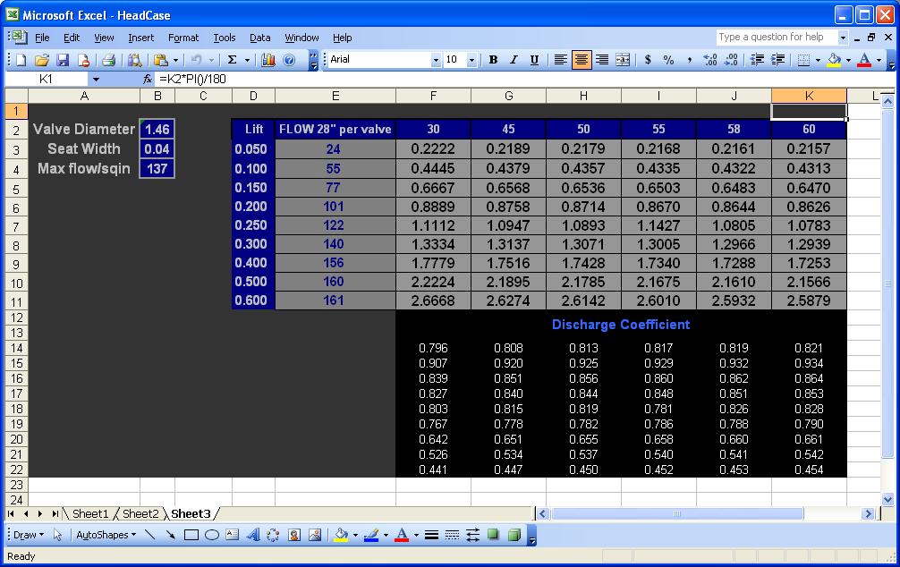
These were with 45 degree seat angle and everything is relative to the curtain area (not the minimum of port and curtain area). The seat angle as tested was stock 45 degrees, so I am getting 0.78 at .300".
The paper I bought has empirical data lifted from a number of engines, I got lucky with one engine, it is a 130 hp per litre engine with the redline around mine at 8,000 rpm and the intake duct length are given along with what various changes do to the power. If I was going to add the variable trumpet feature you would add a 50 mm trumpet piece to gain an extra 40 kw at 5,000 rpm. The duct lengths provided were 400 mm plus 90 mm for the port. I am also looking good with a 60.3 mm internally sized pipe for the manifolding.
I saw another paper were even the slightest bends in the intake trumpets cost power, that was on a SAE racer which uses the Yamaha 600 cc engine. I thought that was interesting. Also in the Ilmor paper which I reread, it talks about the different angles of approach in terms of how straight the port is. With my potential change to the port by "hi porting" That is take all the material out around where the injector sits down to the guide. This makes the air's approach much straighter but according to Ilmor will change the tumble quite a lot. The other negative is by doing this my manifold can not be so straight. When you look at say the Threshie manifold. Because the head's mating surface is horizontal it bolts on and first it goes straight up and then turns. If you look at a Ferrari 599 manifold it is different, it is laid over from the beginning. This is what I want to do and keep the duct as straight as possible. The manifold this way will end up further across the engine by doing it this way.
11-29-2009, 09:46 PM
#20
Addict
Rennlist Member
Rennlist Member
Thread Starter
Tuomo, I can't respond in detail right now, need to clean up the place of all the car parts that have managed to somehow get into the apartment A further bit of empirical evidence is the LPE V6 3.0 litre Nissan Maxima engine fitted with throttle bodies and other bits achieved 400 hp at 8,500 rpm.
It had standard valves and the cam lift was only 0.450" which is very encouraging. Dick Lanford said if bigger valves were fitted 450 hp would be possible but the milage capability would suffer, currently 3,000 miles between builds. On that note I will not be revving the guts out of the engine all the time, in fact I think on very few occasions, timed laps etc. I am going to do a search and find out what size the valves are in those Maxima engines in relation to the bore and see if there is any data on flow rates but I do know there was port work done.
So I think with the heads outstanding flow numbers at low lifts we have a good chance at a big number. Even if the number is not the 800 hp given I wont be fitting a 270 degree cam any figure over 700 is a good one and it is looking increasingly doable, I just wish others might like to get on board to share the success and drive the costs down and also fly the 928 Flag
Thanks Marc for your post, Louie's engine is certainly all working nicely together so it is great to hear the numbers from the experts, appreciate that!
If I didn't mention it I filled the short side radius and that almost always helps low lift numbers. The problem will be making sure the epoxy doesn't come out. My idea is to use Belzona 1111 and then have it coated with a petrol resistant coating and then we should be fine.
Greg
A further bit of empirical evidence is the LPE V6 3.0 litre Nissan Maxima engine fitted with throttle bodies and other bits achieved 400 hp at 8,500 rpm.It had standard valves and the cam lift was only 0.450" which is very encouraging. Dick Lanford said if bigger valves were fitted 450 hp would be possible but the milage capability would suffer, currently 3,000 miles between builds. On that note I will not be revving the guts out of the engine all the time, in fact I think on very few occasions, timed laps etc. I am going to do a search and find out what size the valves are in those Maxima engines in relation to the bore and see if there is any data on flow rates but I do know there was port work done.
So I think with the heads outstanding flow numbers at low lifts we have a good chance at a big number. Even if the number is not the 800 hp given I wont be fitting a 270 degree cam any figure over 700 is a good one and it is looking increasingly doable, I just wish others might like to get on board to share the success and drive the costs down and also fly the 928 Flag
Thanks Marc for your post, Louie's engine is certainly all working nicely together so it is great to hear the numbers from the experts, appreciate that!
If I didn't mention it I filled the short side radius and that almost always helps low lift numbers. The problem will be making sure the epoxy doesn't come out. My idea is to use Belzona 1111 and then have it coated with a petrol resistant coating and then we should be fine.
Greg
11-29-2009, 10:10 PM
#21
Addict
Rennlist Member
Rennlist Member
Thread Starter
It appears that the Nissan may have 34 mm intakes and 29.5 mm exhaust valves with a 93 mm bore. If anybody knows otherwise please let me know. As a ratio it wont be as big as the valves I am using.
Also Tuomo in regards to shrouding, remember that the valves are inclined as such the further you lift the valve the further it moves away from the wall. a big advantage for the 4 valver. Nascar engines have this feature on their 2V heads of course.
Greg
Also Tuomo in regards to shrouding, remember that the valves are inclined as such the further you lift the valve the further it moves away from the wall. a big advantage for the 4 valver. Nascar engines have this feature on their 2V heads of course.
Greg
11-30-2009, 05:11 PM
#22
Addict
Rennlist Member
Rennlist Member
Thread Starter
An article that is quite interesting, it was in one of my books and shows some important relationships with duct sizing.
http://www.profblairandassociates.co..._to_basics.pdf
I am trying to work out how he does his discharge coefficient equations, as I have another paper with details of various engine's discharge co-effiicients at peak lifts and I would like to work out what they actually flow.
Greg
http://www.profblairandassociates.co..._to_basics.pdf
I am trying to work out how he does his discharge coefficient equations, as I have another paper with details of various engine's discharge co-effiicients at peak lifts and I would like to work out what they actually flow.
Greg
12-02-2009, 02:02 PM
#23
Former Sponsor

Well, been thinking about this for a couple of days....tough to know exactly what to say. I considered not saying anything, but thought someone might appreciate some other thoughts.
The flow numbers that I have collected (and they are extensive, since I have my own flow bench) are no where close to any of these numbers that anyone has posted/claimed.
Granted, I never flow heads at high vacuum (I've never seen a racing engine that can pull over 8 inches at WOT...but assuming that there's some engine out there that might be able to pull 10 inches....there is never going to be an engine that pulls anywhere close to 20 or 24 inches....why does anyone bother to test there?) but even converting my numbers to higher vacuum makes no sense.
I do have a set of Theshie's "uber trick" heads....that I can't figure out what the hell to do to fix them....I'll flow them and see what they actually can flow.
With regards to volumetric efficiency....
I've yet to see a 928 engine that can operate in the required rpm ranges nor have the needed intake valve opening events to take advantage of the inertial mass of the incoming air.
I'd calculate that something on the order of 80% volumetric efficient is closer to reality...even with the best intake system. With the stock intake, I'd guess that number to be around 60%.
12-02-2009, 02:32 PM
#24

Well, been thinking about this for a couple of days....tough to know exactly what to say. I considered not saying anything, but thought someone might appreciate some other thoughts.
The flow numbers that I have collected (and they are extensive, since I have my own flow bench) are no where close to any of these numbers that anyone has posted/claimed.
Granted, I never flow heads at high vacuum (I've never seen a racing engine that can pull over 8 inches at WOT...but assuming that there's some engine out there that might be able to pull 10 inches....there is never going to be an engine that pulls anywhere close to 20 or 24 inches....why does anyone bother to test there?) but even converting my numbers to higher vacuum makes no sense.
I do have a set of Theshie's "uber trick" heads....that I can't figure out what the hell to do to fix them....I'll flow them and see what they actually can flow.
With regards to volumetric efficiency....
I've yet to see a 928 engine that can operate in the required rpm ranges nor have the needed intake valve opening events to take advantage of the inertial mass of the incoming air.
I'd calculate that something on the order of 80% volumetric efficient is closer to reality...even with the best intake system. With the stock intake, I'd guess that number to be around 60%.
The flow numbers that I have collected (and they are extensive, since I have my own flow bench) are no where close to any of these numbers that anyone has posted/claimed.
Granted, I never flow heads at high vacuum (I've never seen a racing engine that can pull over 8 inches at WOT...but assuming that there's some engine out there that might be able to pull 10 inches....there is never going to be an engine that pulls anywhere close to 20 or 24 inches....why does anyone bother to test there?) but even converting my numbers to higher vacuum makes no sense.
I do have a set of Theshie's "uber trick" heads....that I can't figure out what the hell to do to fix them....I'll flow them and see what they actually can flow.
With regards to volumetric efficiency....
I've yet to see a 928 engine that can operate in the required rpm ranges nor have the needed intake valve opening events to take advantage of the inertial mass of the incoming air.
I'd calculate that something on the order of 80% volumetric efficient is closer to reality...even with the best intake system. With the stock intake, I'd guess that number to be around 60%.
12-02-2009, 06:25 PM
#25
Addict
Rennlist Member
Rennlist Member
Thread Starter
By GregBRRD
Greg this aspect if I am reading what you saying correctly is just the test vacuum that is required to attain the types of air speeds through the heads that would be relevant. It actually has nothing as far as my knowledge is concerned to do with vacuum in the engine.
There are benches that can pull 60" of vacuum, Darin Morgan has one of these and what you will find is that the more the head flows the better the bench you will need, i.e 10" bench versus 28" bench versus a 60" bench. A 10" bench may drop the test vacuum to 6" or so when flow heads that flow well as they can't keep the pull on the heads going as the flow is filling the void so to speak.
So in summary the higher rated the bench the more it can replicate the actual airspeed happening in the engine, the 60" bench is suppose to replicate engine air running speeds, normally this figure would be 56" but they give themselves some leeway....
It would be interesting to see what flow numbers you get but I think you will probably get close to Phil's published data. Are these one with Ti parts etc?
In regard to volumetric efficiency well my cheapy but very well respected engine program Pipemax says something different, the standard 928 engine say a 4V one is as a generalization around 100% at peak power.
How did I get that? Well in the program you plug in the engine details, bore, stroke rod lengths valve sizes etc but in reality I think it is only size that counts for this calc. and then choose 100% efficiency at how ever many revs you like and it will tell you what power that equates to.
Now I know other board members have much more expensive programs, so maybe they would like to chime in and say what their programs are saying in this regard?
In regard to the flow numbers, are your numbers in 10 or 28"? Some people even flow 25" so my numbers are at 28" just in case that is an issue. As far as the bench that this business uses has been found to replicate the numbers that Airflow Research (AFR) heads publishes within a few cfm and my 2V heads are no where as high.
When the first flow test was conducted by one of the employees he went to get the owner to make sure nothing was wrong with the bench! (because of the numbers) This time the usual flow bench operator who is bit of stickler to detail conducted the last test and he said the best set of flow numbers down low on the intake side he has seen. He wasn't surprised when the numbers decreased when I removed (made the port larger) the putty to build up the (SSR) short side radius.
As far as getting the air speed right and ram effect etc, that is obviously difficult, that is why I buy as much research as I can. That is why I also put it out these for others to come in a share the benefits and costs of the project, with replication comes cost savings.
Below is the Cosworth port from the I beam head, it is very short due to the F1 regs regarding not being able to change the head design but have a look at the taper and you can see that they are using after the guides or the start of the port on this head as a diffuser, this is the most common type of port design in high end engines these days and what I tried to adapt to the Porsche port. It looks like it has been somewhat successful.

Greg
Granted, I never flow heads at high vacuum (I've never seen a racing engine that can pull over 8 inches at WOT...but assuming that there's some engine out there that might be able to pull 10 inches....there is never going to be an engine that pulls anywhere close to 20 or 24 inches....why does anyone bother to test there?) but even converting my numbers to higher vacuum makes no sense.
There are benches that can pull 60" of vacuum, Darin Morgan has one of these and what you will find is that the more the head flows the better the bench you will need, i.e 10" bench versus 28" bench versus a 60" bench. A 10" bench may drop the test vacuum to 6" or so when flow heads that flow well as they can't keep the pull on the heads going as the flow is filling the void so to speak.
So in summary the higher rated the bench the more it can replicate the actual airspeed happening in the engine, the 60" bench is suppose to replicate engine air running speeds, normally this figure would be 56" but they give themselves some leeway....
I do have a set of Theshie's "uber trick" heads....that I can't figure out what the hell to do to fix them....I'll flow them and see what they actually can flow.
With regards to volumetric efficiency....
I've yet to see a 928 engine that can operate in the required rpm ranges nor have the needed intake valve opening events to take advantage of the inertial mass of the incoming air.
I'd calculate that something on the order of 80% volumetric efficient is closer to reality...even with the best intake system. With the stock intake, I'd guess that number to be around 60%.
In regard to volumetric efficiency well my cheapy but very well respected engine program Pipemax says something different, the standard 928 engine say a 4V one is as a generalization around 100% at peak power.
How did I get that? Well in the program you plug in the engine details, bore, stroke rod lengths valve sizes etc but in reality I think it is only size that counts for this calc. and then choose 100% efficiency at how ever many revs you like and it will tell you what power that equates to.
Now I know other board members have much more expensive programs, so maybe they would like to chime in and say what their programs are saying in this regard?
In regard to the flow numbers, are your numbers in 10 or 28"? Some people even flow 25" so my numbers are at 28" just in case that is an issue. As far as the bench that this business uses has been found to replicate the numbers that Airflow Research (AFR) heads publishes within a few cfm and my 2V heads are no where as high.
When the first flow test was conducted by one of the employees he went to get the owner to make sure nothing was wrong with the bench! (because of the numbers) This time the usual flow bench operator who is bit of stickler to detail conducted the last test and he said the best set of flow numbers down low on the intake side he has seen. He wasn't surprised when the numbers decreased when I removed (made the port larger) the putty to build up the (SSR) short side radius.
As far as getting the air speed right and ram effect etc, that is obviously difficult, that is why I buy as much research as I can. That is why I also put it out these for others to come in a share the benefits and costs of the project, with replication comes cost savings.
Below is the Cosworth port from the I beam head, it is very short due to the F1 regs regarding not being able to change the head design but have a look at the taper and you can see that they are using after the guides or the start of the port on this head as a diffuser, this is the most common type of port design in high end engines these days and what I tried to adapt to the Porsche port. It looks like it has been somewhat successful.
Greg
12-02-2009, 07:41 PM
#26
Nordschleife Master
Granted, I never flow heads at high vacuum (I've never seen a racing engine that can pull over 8 inches at WOT...but assuming that there's some engine out there that might be able to pull 10 inches....there is never going to be an engine that pulls anywhere close to 20 or 24 inches....why does anyone bother to test there?) but even converting my numbers to higher vacuum makes no sense.
With regards to volumetric efficiency.... I've yet to see a 928 engine that can operate in the required rpm ranges nor have the needed intake valve opening events to take advantage of the inertial mass of the incoming air.I'd calculate that something on the order of 80% volumetric efficient is closer to reality...even with the best intake system. With the stock intake, I'd guess that number to be around 60%.
12-02-2009, 09:46 PM
#28
Rennlist Member
we used the 100mm bore dia at 28" for flow. And our flow starts going flat after 11mm lift, hence the B1 cam specs.
The cams were designed for maximum "productivity"...the blend of lift, reliability, drivability, vacuum, etc.
I designed the port geometry (and cams) about 10 years ago, and have since made some improvements in heads...and now have a set of heads that are partially finished that should outflow those ports but will require a custom intake due to not enough meat in the stock intake to "bore out". Really need that 5 axis milling center now!!!
Steve...where are ya man??!!
Time is all it takes.
12-02-2009, 09:56 PM
#29
Former Sponsor
Volumetric Efficiency of stock 928:
Assuming .400 cam lift and stock airflow from Greg's 1st post: CFMs=267
Displacement=302 cubic inches
At 6,000 rpm, the volumetric efficiency is 50.92%
Assuming .400 cam lift and stock airflow from Greg's 1st post: CFMs=267
Displacement=302 cubic inches
At 6,000 rpm, the volumetric efficiency is 50.92%
12-02-2009, 10:10 PM
#30
Nordschleife Master
From my sims, I am getting actual SCFM number of 460 at 6000 rpm for all eight cylinders combined.
Another way to go at it is BSFC. Say BSFC is 0.51 and AFR is 12.5. The engine makes about 312 hp at 6000 rpm. This would again result in 87% VE.