
Just a preview of an SC setup
 07-24-2015, 11:26 PM
#181
Addict
Rennlist Member
Rennlist Member
Thread Starter
Join Date: Feb 2004
Location: Monterey Peninsula, CA
Posts: 2,374
Likes: 0
Received 16 Likes
on
12 Posts
Originally Posted by Imo000
Asking the customer to port mach the head and the gaket is disaster waiting to happen. Give people a chance to screw up and they will. Isn't the OE manofold's footprint good enough to make this work well without grinding the head ports and the gasket?
Most port maching doesn't work too well because the gasket and the intake manifold slightly shifts during installation so a perfect transition will need locator pins or else it will have a ridge.
Most port maching doesn't work too well because the gasket and the intake manifold slightly shifts during installation so a perfect transition will need locator pins or else it will have a ridge.
If someone doesn't have the skills to do it, it can be prepared as decently as possible in my shop.
However, it may not be a kit situation, but more of an I supervise and or perform all installation similar to how John Kuhn's process works. (This is not yet decided, as I don't know how many will be sold.)
For my personal setup, it will be port matched to my heads probably with a polymer gasket and hylomar.
Best regards
Last edited by blau928; 07-25-2015 at 03:33 AM.
 08-01-2015, 02:23 PM
#182
Addict
Rennlist Member
Rennlist Member
Thread Starter
Join Date: Feb 2004
Location: Monterey Peninsula, CA
Posts: 2,374
Likes: 0
Received 16 Likes
on
12 Posts
Here are some revisions that were done to make the lower sub assembly one piece for casting. The edges of the lower flat plate were trimmed back to be a more easy fit into the valley of the V8 as the mounting holes are as good as I can get them to use the mounting studs as dowel pins as shown in the previous test fits with the milled plastic piece.
In the previous versions, it was also 3 pieces plus the fuel rails and injectors. Now it's just one piece lower assembly plus the rails and injectors.
Obviously the injector rails will not be cast......
I'll be discussing casting with the foundry next week, and see what tweaks they need to proceed. I'll post updates after that..
Cheers
08-01-2015, 02:45 PM
#183
Nordschleife Master
Do you think it might be possible to design two symmetrical pieces from that such that both parts could be produced from the same mold patterns? They look pretty symmetric so maybe that would be possible. It would be a lot smaller part to cast and twice as large of a series.
Here's one idea. I don't know if this will work, but it's worth thinking about. First, water jet (or whatnot) a flat plate for the base. This is a two dimensional piece and can be cut from aluminum plate so its reasonably economical to fabricate. Second, cast two identical pieces with runners and plenum base and use the same casting on both sides. Much like Porsche used the same head casting on both sides.
Here's one idea. I don't know if this will work, but it's worth thinking about. First, water jet (or whatnot) a flat plate for the base. This is a two dimensional piece and can be cut from aluminum plate so its reasonably economical to fabricate. Second, cast two identical pieces with runners and plenum base and use the same casting on both sides. Much like Porsche used the same head casting on both sides.
Here are some revisions that were done to make the lower sub assembly one piece for casting. The edges of the lower flat plate were trimmed back to be a more easy fit into the valley of the V8 as the mounting holes are as good as I can get them to use the mounting studs as dowel pins as shown in the previous test fits with the milled plastic piece.
In the previous versions, it was also 3 pieces plus the fuel rails and injectors. Now it's just one piece lower assembly plus the rails and injectors.
Obviously the injector rails will not be cast......
I'll be discussing casting with the foundry next week, and see what tweaks they need to proceed. I'll post updates after that..
Cheers
In the previous versions, it was also 3 pieces plus the fuel rails and injectors. Now it's just one piece lower assembly plus the rails and injectors.
Obviously the injector rails will not be cast......
I'll be discussing casting with the foundry next week, and see what tweaks they need to proceed. I'll post updates after that..
Cheers
Last edited by ptuomov; 08-01-2015 at 05:33 PM.
08-01-2015, 10:18 PM
#184
Addict
Rennlist Member
Rennlist Member
Thread Starter
Join Date: Feb 2004
Location: Monterey Peninsula, CA
Posts: 2,374
Likes: 0
Received 16 Likes
on
12 Posts
Originally Posted by ptuomov
Do you think it might be possible to design two symmetrical pieces from that such that both parts could be produced from the same mold patterns? They look pretty symmetric so maybe that would be possible. It would be a lot smaller part to cast and twice as large of a series.
Here's one idea. I don't know if this will work, but it's worth thinking about. First, water jet (or whatnot) a flat plate for the base. This is a two dimensional piece and can be cut from aluminum plate so its reasonably economical to fabricate. Second, cast two identical pieces with runners and plenum base and use the same casting on both sides. Much like Porsche used the same head casting on both sides.
Here's one idea. I don't know if this will work, but it's worth thinking about. First, water jet (or whatnot) a flat plate for the base. This is a two dimensional piece and can be cut from aluminum plate so its reasonably economical to fabricate. Second, cast two identical pieces with runners and plenum base and use the same casting on both sides. Much like Porsche used the same head casting on both sides.
The base plate is needed for strength as the compressor needs shear forces to be addressed or it will dislodge from the mount points.
In any event, one version requires more cnc finishing and one version requires less but more casting complications... An exercise in trade offs...
Typical 928 engine room stuff!!
Best regards
08-07-2015, 02:12 PM
#185
Addict
Rennlist Member
Rennlist Member
Thread Starter
Join Date: Feb 2004
Location: Monterey Peninsula, CA
Posts: 2,374
Likes: 0
Received 16 Likes
on
12 Posts
Originally Posted by ptuomov
Do you think it might be possible to design two symmetrical pieces from that such that both parts could be produced from the same mold patterns? They look pretty symmetric so maybe that would be possible. It would be a lot smaller part to cast and twice as large of a series.
Here's one idea. I don't know if this will work, but it's worth thinking about. First, water jet (or whatnot) a flat plate for the base. This is a two dimensional piece and can be cut from aluminum plate so its reasonably economical to fabricate. Second, cast two identical pieces with runners and plenum base and use the same casting on both sides. Much like Porsche used the same head casting on both sides.
Here's one idea. I don't know if this will work, but it's worth thinking about. First, water jet (or whatnot) a flat plate for the base. This is a two dimensional piece and can be cut from aluminum plate so its reasonably economical to fabricate. Second, cast two identical pieces with runners and plenum base and use the same casting on both sides. Much like Porsche used the same head casting on both sides.
Once I get the list of requirements, it goes back to my engineer for tweaking. Then back to the casting shop and foundry...
The cycle begins.......
08-07-2015, 02:27 PM
#186
Just a thought......
could liquid nitrogen be used to lower temps of s/c? I'm thinking maybe running it through finned tubing in strategic points in the enginebay, possibly through internal channels.
could liquid nitrogen be used to lower temps of s/c? I'm thinking maybe running it through finned tubing in strategic points in the enginebay, possibly through internal channels.
08-07-2015, 02:40 PM
#187
Archive Gatekeeper
Rennlist Member
Rennlist Member
You'd need an awful lot of LN2 to cool everything to the point where it would stop boiling in the tubes, at which point all moisture in the intake air would condense and freeze on the cooling coils and the engine would come to a stop.
 08-07-2015, 02:49 PM
#188
Addict
Rennlist Member
Rennlist Member
Thread Starter
Join Date: Feb 2004
Location: Monterey Peninsula, CA
Posts: 2,374
Likes: 0
Received 16 Likes
on
12 Posts
Originally Posted by blackbull
Just a thought......
could liquid nitrogen be used to lower temps of s/c? I'm thinking maybe running it through finned tubing in strategic points in the enginebay, possibly through internal channels.
could liquid nitrogen be used to lower temps of s/c? I'm thinking maybe running it through finned tubing in strategic points in the enginebay, possibly through internal channels.
However, my initial off the cuff concerns would be around management of the liquid nitrogen given that it is-340F or thereabouts..
If your thoughts were to use it as a closed system, once the system absorbs heat, the liquid will expand and unless there is a heat exchanger to get the input heat out, the phase change to gas will cause the system to burst..
Many hot rodders just use a CO2 spray on the air-air intercooler or the air-water intercooler radiator to lower the temperature. CO2 is cheap and readily obtained..
I suspect you can do the same with a LN2 system, but I have never done one, so I can't comment from experience with LN2.
Hope that helps.
 08-07-2015, 03:43 PM
#189
Nordschleife Master
If one is running a liquid-coolant intercooler in a street car that has air conditioning, I think one should consider the following system patented by Ford.
In its simplest form, the air-conditioning fluid return line is run thru a coil that sits inside the intercooler fluid reservoir. That's not the optimal arrangement, but it'll give some benefit.
A better but more complicated system would have the supercooled intercooler fluid reservoir separated from the normal intercooler fluid circulation except at high loads, using the supercooling only when it's needed the most.
The version as patented by Ford:
---
SUMMARY OF THE INVENTION
A charge air management system for an automotive engine includes a coolant reservoir containing a quantity of liquid coolant and a refrigeration system for removing heat from the liquid coolant within the reservoir. A charge air-to-liquid coolant heat exchanger receives refrigerated coolant from the reservoir and chills charge air entering the engine.
A refrigeration system according to the present invention preferably comprises a refrigerant compressor driven by the engine and a condenser for receiving high pressure refrigerant vapor from the compressor and for liquefying the refrigerant. An evaporator is housed within the coolant reservoir for the purpose of receiving liquid refrigerant from the condenser and for absorbing heat from the liquid coolant as the refrigerant changes phase from a liquid to a gaseous state.
According to another aspect of the present invention, a refrigeration system may further comprise an ambient air-to-liquid coolant heat exchanger for removing heat from the liquid coolant. Alternatively, the system may further comprise an ambient air-to-charge air heat exchanger for cooling the charge air before the charge air-to-liquid heat exchanger.
A system according to the present invention also preferably includes an engine driven booster such as a turbocharger or a supercharger for increasing the quantity of charge air entering the engine's air inlet. In such case, the charge air-to-liquid coolant heat exchanger will be positioned between the booster and the air inlet for receiving refrigerated coolant from the reservoir and for chilling charge air entering the air inlet.
A control system, which may comprise part of the engine's electronic control module, may be employed for controlling the recirculation of liquid coolant between only the ambient air-to-liquid coolant heat exchanger and the charge air-to-liquid coolant heat exchanger during engine operation at lower loads, while recirculating liquid coolant between only the coolant reservoir and the charge air-to-liquid coolant heat exchanger during engine operation at higher loads.
A control system incorporated as a part of the present invention will operate the booster, whether it be a turbocharger or supercharger, so that the quantity of charge air entering the engine is adjusted according to the temperature of the liquid coolant, with the quantity of charge air being increased in the event the temperature of the liquid coolant is less than a predetermined threshold. If desired, the refrigerant compressor comprising a portion of the present invention may be used for supplying airconditioning to the passenger cab of an automotive vehicle.
It is an advantage of the present invention that a system according to the present invention may be used to intermittently increase the output of an automotive engine without the need for nitrous oxide, without the need for higher blower overdrive ratios, and without the need for an oversized turbocharger, all of which increase the cost of an automotive engine.
BRIEF DESCRIPTION OF THE DRAWINGS
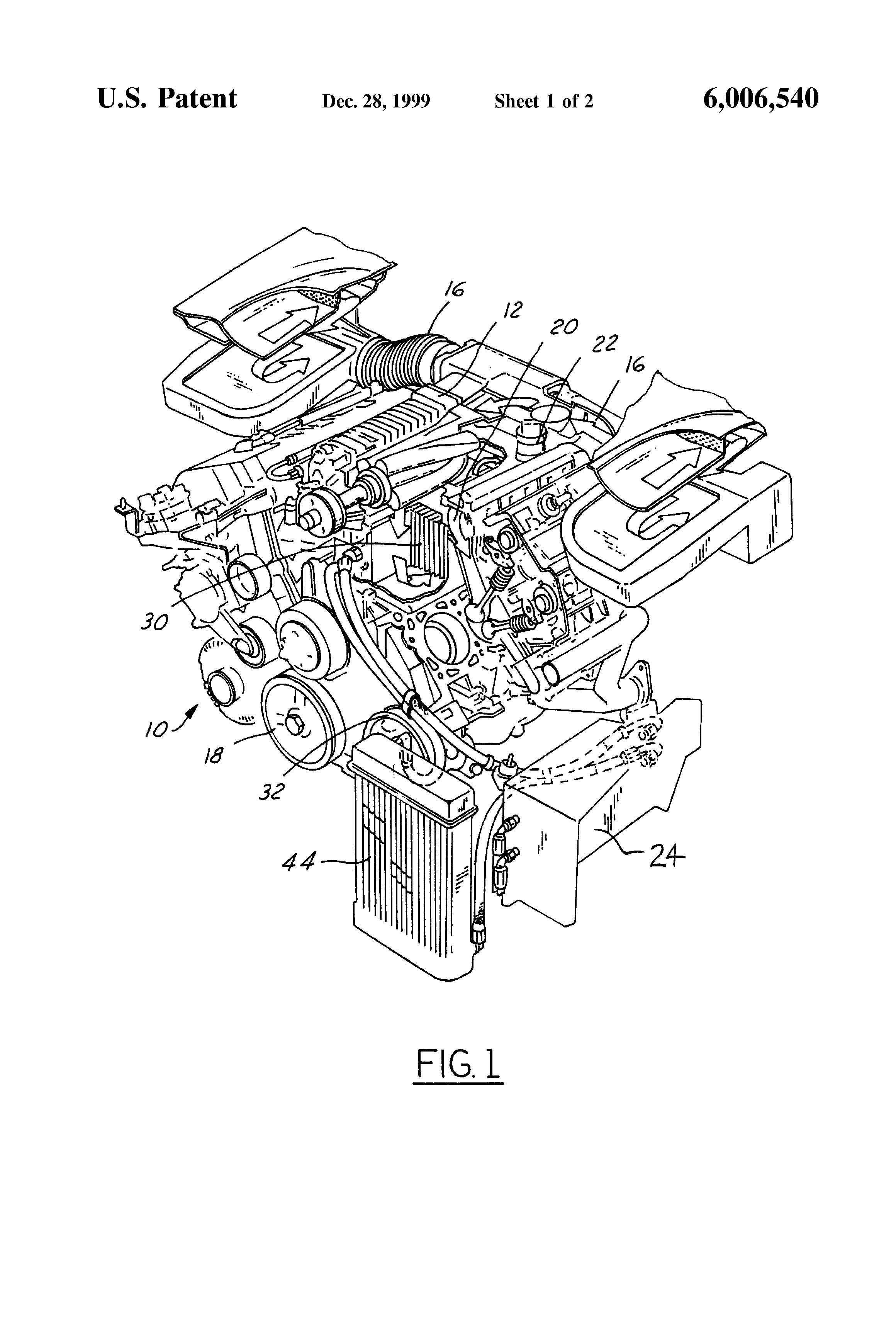
FIG. 1 is a schematic representation of a V-block engine having a charge air management system according to the present invention.
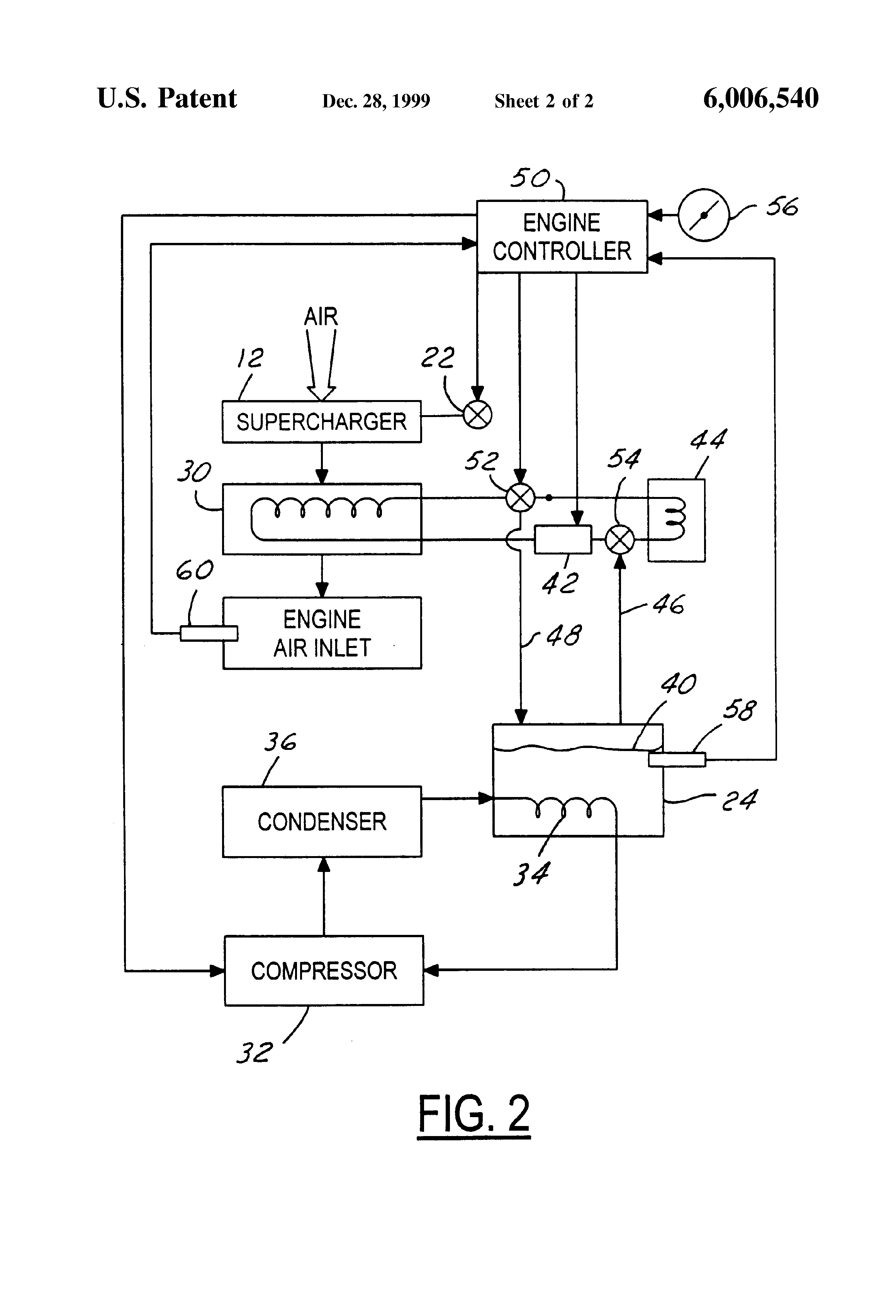
FIG. 2 is a schematic representation of a system including controls according to the present invention.
DETAILED DESCRIPTION OF PREFERRED EMBODIMENTS
As shown in FIG. 1, engine 10 has supercharger 12, which is driven by a belt coupled to crankshaft 18. Charge air entering the engine's induction system through intake 16 flows through supercharger 12 and then ultimately through air inlet 20. Prior to flowing through air inlet 20, charge air moves through charge air-to-liquid coolant heat exchanger 30. Heat from the charge air, which is extracted by charge air-to-liquid coolant heat exchanger 30, is passed to the ambient atmosphere by means of ambient air-to-liquid coolant heat exchanger 44. However, during high load operation, refrigerated liquid coolant from coolant reservoir 24 is used to flood charge air-to-liquid coolant heat exchanger 30, with the result that the air charge entering the engine is more dense, with the further result that more fuel can be supplied to the engine for a much greater power output.
Continuing now with FIG. 2, engine controller 50 operates control valves 52 and 54 which have as their purpose controlling the flow of liquid coolant 40 such that liquid coolant 40 either recirculates between charge air-to-liquid coolant heat exchanger 30 and ambient air-to-liquid coolant heat exchanger 44 or between air-to-liquid coolant heat exchanger 30 and reservoir 24. Thus, when valves 52 and 54 are set so as to bypass heat exchanger 44, liquid coolant 40 is drawn from reservoir 24 and passes through line 46 through valve 54, then through circulating pump 42, and then into charge air-to-liquid coolant heat exchanger 30. After liquid coolant 40 has circulated through exchanger 30, valve 52 directs liquid coolant through line 48 to reservoir 24.
Heat is extracted from reservoir 24 by means of compressor 32 (see also FIG. 1), which supplies compressed refrigerant vapor to condenser 36, which in turn changes vapor to a liquid and sends it to evaporator 34. Of course, the refrigerant changes phase to a vapor in evaporator 34 thereby extracting heat from liquid coolant 40 within reservoir 24.
Engine controller 50 receives a signal from throttle position sensor 56. This signal is a measure of engine load. Those skilled in the art will appreciate, however, that other types of engine load detection devices could be used such as rpm detection, spark timing, and other sorts of devices. In any event, when liquid coolant 40 from reservoir 24 is circulating through heat exchanger 30, engine controller 50 may increase the boost provided by supercharger 12 by means of boost controller 22.
Engine controller 50 keeps track of the temperature of liquid coolant 40 within reservoir 24 by means of temperature sensor 58. Engine air inlet temperature is also monitored by means of temperature sensor 60. In the event that the engine air inlet temperature is too great or the temperature of liquid coolant 40 within reservoir 24 is too high, the boost will not be increased by means of boost control 22 and the liquid coolant will not be circulated from reservoir 24 to heat exchanger 30. Those skilled in the art will appreciate in view of this disclosure that controller 50 could comprise an engine controller unit of the type commonly employed with automotive engines, or alternatively, a stand-alone computer dedicated solely to operation of the present air charge handling system.
In its simplest form, the air-conditioning fluid return line is run thru a coil that sits inside the intercooler fluid reservoir. That's not the optimal arrangement, but it'll give some benefit.
A better but more complicated system would have the supercooled intercooler fluid reservoir separated from the normal intercooler fluid circulation except at high loads, using the supercooling only when it's needed the most.
The version as patented by Ford:
---
SUMMARY OF THE INVENTION
A charge air management system for an automotive engine includes a coolant reservoir containing a quantity of liquid coolant and a refrigeration system for removing heat from the liquid coolant within the reservoir. A charge air-to-liquid coolant heat exchanger receives refrigerated coolant from the reservoir and chills charge air entering the engine.
A refrigeration system according to the present invention preferably comprises a refrigerant compressor driven by the engine and a condenser for receiving high pressure refrigerant vapor from the compressor and for liquefying the refrigerant. An evaporator is housed within the coolant reservoir for the purpose of receiving liquid refrigerant from the condenser and for absorbing heat from the liquid coolant as the refrigerant changes phase from a liquid to a gaseous state.
According to another aspect of the present invention, a refrigeration system may further comprise an ambient air-to-liquid coolant heat exchanger for removing heat from the liquid coolant. Alternatively, the system may further comprise an ambient air-to-charge air heat exchanger for cooling the charge air before the charge air-to-liquid heat exchanger.
A system according to the present invention also preferably includes an engine driven booster such as a turbocharger or a supercharger for increasing the quantity of charge air entering the engine's air inlet. In such case, the charge air-to-liquid coolant heat exchanger will be positioned between the booster and the air inlet for receiving refrigerated coolant from the reservoir and for chilling charge air entering the air inlet.
A control system, which may comprise part of the engine's electronic control module, may be employed for controlling the recirculation of liquid coolant between only the ambient air-to-liquid coolant heat exchanger and the charge air-to-liquid coolant heat exchanger during engine operation at lower loads, while recirculating liquid coolant between only the coolant reservoir and the charge air-to-liquid coolant heat exchanger during engine operation at higher loads.
A control system incorporated as a part of the present invention will operate the booster, whether it be a turbocharger or supercharger, so that the quantity of charge air entering the engine is adjusted according to the temperature of the liquid coolant, with the quantity of charge air being increased in the event the temperature of the liquid coolant is less than a predetermined threshold. If desired, the refrigerant compressor comprising a portion of the present invention may be used for supplying airconditioning to the passenger cab of an automotive vehicle.
It is an advantage of the present invention that a system according to the present invention may be used to intermittently increase the output of an automotive engine without the need for nitrous oxide, without the need for higher blower overdrive ratios, and without the need for an oversized turbocharger, all of which increase the cost of an automotive engine.
BRIEF DESCRIPTION OF THE DRAWINGS
FIG. 1 is a schematic representation of a V-block engine having a charge air management system according to the present invention.
FIG. 2 is a schematic representation of a system including controls according to the present invention.
DETAILED DESCRIPTION OF PREFERRED EMBODIMENTS
As shown in FIG. 1, engine 10 has supercharger 12, which is driven by a belt coupled to crankshaft 18. Charge air entering the engine's induction system through intake 16 flows through supercharger 12 and then ultimately through air inlet 20. Prior to flowing through air inlet 20, charge air moves through charge air-to-liquid coolant heat exchanger 30. Heat from the charge air, which is extracted by charge air-to-liquid coolant heat exchanger 30, is passed to the ambient atmosphere by means of ambient air-to-liquid coolant heat exchanger 44. However, during high load operation, refrigerated liquid coolant from coolant reservoir 24 is used to flood charge air-to-liquid coolant heat exchanger 30, with the result that the air charge entering the engine is more dense, with the further result that more fuel can be supplied to the engine for a much greater power output.
Continuing now with FIG. 2, engine controller 50 operates control valves 52 and 54 which have as their purpose controlling the flow of liquid coolant 40 such that liquid coolant 40 either recirculates between charge air-to-liquid coolant heat exchanger 30 and ambient air-to-liquid coolant heat exchanger 44 or between air-to-liquid coolant heat exchanger 30 and reservoir 24. Thus, when valves 52 and 54 are set so as to bypass heat exchanger 44, liquid coolant 40 is drawn from reservoir 24 and passes through line 46 through valve 54, then through circulating pump 42, and then into charge air-to-liquid coolant heat exchanger 30. After liquid coolant 40 has circulated through exchanger 30, valve 52 directs liquid coolant through line 48 to reservoir 24.
Heat is extracted from reservoir 24 by means of compressor 32 (see also FIG. 1), which supplies compressed refrigerant vapor to condenser 36, which in turn changes vapor to a liquid and sends it to evaporator 34. Of course, the refrigerant changes phase to a vapor in evaporator 34 thereby extracting heat from liquid coolant 40 within reservoir 24.
Engine controller 50 receives a signal from throttle position sensor 56. This signal is a measure of engine load. Those skilled in the art will appreciate, however, that other types of engine load detection devices could be used such as rpm detection, spark timing, and other sorts of devices. In any event, when liquid coolant 40 from reservoir 24 is circulating through heat exchanger 30, engine controller 50 may increase the boost provided by supercharger 12 by means of boost controller 22.
Engine controller 50 keeps track of the temperature of liquid coolant 40 within reservoir 24 by means of temperature sensor 58. Engine air inlet temperature is also monitored by means of temperature sensor 60. In the event that the engine air inlet temperature is too great or the temperature of liquid coolant 40 within reservoir 24 is too high, the boost will not be increased by means of boost control 22 and the liquid coolant will not be circulated from reservoir 24 to heat exchanger 30. Those skilled in the art will appreciate in view of this disclosure that controller 50 could comprise an engine controller unit of the type commonly employed with automotive engines, or alternatively, a stand-alone computer dedicated solely to operation of the present air charge handling system.
08-07-2015, 04:14 PM
#190
Addict
Rennlist Member
Rennlist Member
Thread Starter
Join Date: Feb 2004
Location: Monterey Peninsula, CA
Posts: 2,374
Likes: 0
Received 16 Likes
on
12 Posts
Originally Posted by ptuomov
If one is running a liquid-coolant intercooler in a street car that has air conditioning, I think one should consider the following system patented by Ford.
In its simplest form, the air-conditioning fluid return line is run thru a coil that sits inside the intercooler fluid reservoir. That's not the optimal arrangement, but it'll give some benefit.
A better but more complicated system would have the supercooled intercooler fluid reservoir separated from the normal intercooler fluid circulation except at high loads, using the supercooling only when it's needed the most.
The version as patented by Ford:
---
Attachment 961228
Attachment 961229
SUMMARY OF THE INVENTION
A charge air management system for an automotive engine includes a coolant reservoir containing a quantity of liquid coolant and a refrigeration system for removing heat from the liquid coolant within the reservoir. A charge air-to-liquid coolant heat exchanger receives refrigerated coolant from the reservoir and chills charge air entering the engine.
A refrigeration system according to the present invention preferably comprises a refrigerant compressor driven by the engine and a condenser for receiving high pressure refrigerant vapor from the compressor and for liquefying the refrigerant. An evaporator is housed within the coolant reservoir for the purpose of receiving liquid refrigerant from the condenser and for absorbing heat from the liquid coolant as the refrigerant changes phase from a liquid to a gaseous state.
According to another aspect of the present invention, a refrigeration system may further comprise an ambient air-to-liquid coolant heat exchanger for removing heat from the liquid coolant. Alternatively, the system may further comprise an ambient air-to-charge air heat exchanger for cooling the charge air before the charge air-to-liquid heat exchanger.
A system according to the present invention also preferably includes an engine driven booster such as a turbocharger or a supercharger for increasing the quantity of charge air entering the engine's air inlet. In such case, the charge air-to-liquid coolant heat exchanger will be positioned between the booster and the air inlet for receiving refrigerated coolant from the reservoir and for chilling charge air entering the air inlet.
A control system, which may comprise part of the engine's electronic control module, may be employed for controlling the recirculation of liquid coolant between only the ambient air-to-liquid coolant heat exchanger and the charge air-to-liquid coolant heat exchanger during engine operation at lower loads, while recirculating liquid coolant between only the coolant reservoir and the charge air-to-liquid coolant heat exchanger during engine operation at higher loads.
A control system incorporated as a part of the present invention will operate the booster, whether it be a turbocharger or supercharger, so that the quantity of charge air entering the engine is adjusted according to the temperature of the liquid coolant, with the quantity of charge air being increased in the event the temperature of the liquid coolant is less than a predetermined threshold. If desired, the refrigerant compressor comprising a portion of the present invention may be used for supplying airconditioning to the passenger cab of an automotive vehicle.
It is an advantage of the present invention that a system according to the present invention may be used to intermittently increase the output of an automotive engine without the need for nitrous oxide, without the need for higher blower overdrive ratios, and without the need for an oversized turbocharger, all of which increase the cost of an automotive engine.
BRIEF DESCRIPTION OF THE DRAWINGS
FIG. 1 is a schematic representation of a V-block engine having a charge air management system according to the present invention.
FIG. 2 is a schematic representation of a system including controls according to the present invention.
DETAILED DESCRIPTION OF PREFERRED EMBODIMENTS
As shown in FIG. 1, engine 10 has supercharger 12, which is driven by a belt coupled to crankshaft 18. Charge air entering the engine's induction system through intake 16 flows through supercharger 12 and then ultimately through air inlet 20. Prior to flowing through air inlet 20, charge air moves through charge air-to-liquid coolant heat exchanger 30. Heat from the charge air, which is extracted by charge air-to-liquid coolant heat exchanger 30, is passed to the ambient atmosphere by means of ambient air-to-liquid coolant heat exchanger 44. However, during high load operation, refrigerated liquid coolant from coolant reservoir 24 is used to flood charge air-to-liquid coolant heat exchanger 30, with the result that the air charge entering the engine is more dense, with the further result that more fuel can be supplied to the engine for a much greater power output.
Continuing now with FIG. 2, engine controller 50 operates control valves 52 and 54 which have as their purpose controlling the flow of liquid coolant 40 such that liquid coolant 40 either recirculates between charge air-to-liquid coolant heat exchanger 30 and ambient air-to-liquid coolant heat exchanger 44 or between air-to-liquid coolant heat exchanger 30 and reservoir 24. Thus, when valves 52 and 54 are set so as to bypass heat exchanger 44, liquid coolant 40 is drawn from reservoir 24 and passes through line 46 through valve 54, then through circulating pump 42, and then into charge air-to-liquid coolant heat exchanger 30. After liquid coolant 40 has circulated through exchanger 30, valve 52 directs liquid coolant through line 48 to reservoir 24.
Heat is extracted from reservoir 24 by means of compressor 32 (see also FIG. 1), which supplies compressed refrigerant vapor to condenser 36, which in turn changes vapor to a liquid and sends it to evaporator 34. Of course, the refrigerant changes phase to a vapor in evaporator 34 thereby extracting heat from liquid coolant 40 within reservoir 24.
Engine controller 50 receives a signal from throttle position sensor 56. This signal is a measure of engine load. Those skilled in the art will appreciate, however, that other types of engine load detection devices could be used such as rpm detection, spark timing, and other sorts of devices. In any event, when liquid coolant 40 from reservoir 24 is circulating through heat exchanger 30, engine controller 50 may increase the boost provided by supercharger 12 by means of boost controller 22.
Engine controller 50 keeps track of the temperature of liquid coolant 40 within reservoir 24 by means of temperature sensor 58. Engine air inlet temperature is also monitored by means of temperature sensor 60. In the event that the engine air inlet temperature is too great or the temperature of liquid coolant 40 within reservoir 24 is too high, the boost will not be increased by means of boost control 22 and the liquid coolant will not be circulated from reservoir 24 to heat exchanger 30. Those skilled in the art will appreciate in view of this disclosure that controller 50 could comprise an engine controller unit of the type commonly employed with automotive engines, or alternatively, a stand-alone computer dedicated solely to operation of the present air charge handling system.
I thought about plumbing the AWIC supply lines through another Laminova core that would connect to the rear AC lines so the supply of the AWIC liquid would be cooled below ambient on the way to the AWIC.
I didn't do any calculations, but looking at ford's system, it may be possible to do just that. The question is will it allows more power after you subtract the power needed to drive the AC compressor.....
I also toyed with the same idea using CO2 spray to super cool the AWIC supply lines with a Laminova core on the supply lines. The CO2 would then be released to atmosphere after freezing the core in the supply line.
08-07-2015, 04:19 PM
#191

A simple methanol pre-port injection to reduce iats would be more effective than the "killer chiller" in Mercedes aftermarket speak for the ac system one.
08-07-2015, 04:55 PM
#192
Nordschleife Master
You want to accumulate the "cool" over a long period of time, preferrably from wasted ac discharge. Then release the cool when the intake air temp goes over some threshold. Since the car rarely runs at peak load, the math really works out. Much like with gasoline-electric hybrids.
Interesting......
I thought about plumbing the AWIC supply lines through another Laminova core that would connect to the rear AC lines so the supply of the AWIC liquid would be cooled below ambient on the way to the AWIC.
I didn't do any calculations, but looking at ford's system, it may be possible to do just that. The question is will it allows more power after you subtract the power needed to drive the AC compressor.....
I also toyed with the same idea using CO2 spray to super cool the AWIC supply lines with a Laminova core on the supply lines. The CO2 would then be released to atmosphere after freezing the core in the supply line.
08-07-2015, 06:44 PM
#193
Addict
Rennlist Member
Rennlist Member
Thread Starter
Join Date: Feb 2004
Location: Monterey Peninsula, CA
Posts: 2,374
Likes: 0
Received 16 Likes
on
12 Posts
Originally Posted by BC
A simple methanol pre-port injection to reduce iats would be more effective than the "killer chiller" in Mercedes aftermarket speak for the ac system one.
We shall see.....
08-07-2015, 06:56 PM
#194
Addict
Rennlist Member
Rennlist Member
Thread Starter
Join Date: Feb 2004
Location: Monterey Peninsula, CA
Posts: 2,374
Likes: 0
Received 16 Likes
on
12 Posts
Originally Posted by ptuomov
You want to accumulate the "cool" over a long period of time, preferrably from wasted ac discharge. Then release the cool when the intake air temp goes over some threshold. Since the car rarely runs at peak load, the math really works out. Much like with gasoline-electric hybrids.
It might be better then to place the secondary AC piece inside the AWIC water tank to continuously cool the water below ambient...
BTW,
The AWIC pump on my system only turns on at certain load points with a short burst after each event to flush the lines. It isn't continuous like most setups out there..