

Girdle oil passage modifications
 10-02-2009, 12:19 PM
#31
Honestly, you have a more calculated approach to your modifications. I agree with what you've shown entirely. I would also radius the edge on the floor where the oil flows in and turns toward the left in the oil channel. I have a practical logic combined with experience where I concoct my ideas. I don't see this in terms of pressure because a fluids non-compressible nature. I see it as speed, inertia, and viscosity. Oil moving by at that speed has too much inertia to make the sharp bend at its viscosity. I agree that slowing it down there is intelligent and should yield tangible results. I'm thinking about making a plexiglass top for mine and pumping fluid through it and recording the results for analyzing.
 10-02-2009, 12:41 PM
#32
By the way, I've got an evo here I built a while back that made 500hp roughly at the crankshaft and spins to 8500 rpm all on pump gas. Crossdrilled oil passages surely aren't too bad because that's what they have from the factory and are pretty reliable at that rpm with decent hardware. Interestingly, the crossdrilling at the mains and rods are the same diameter whereas the Porsche has the same size mains, in not a couple thousandths bigger, than the Evo but the rods are drilled smaller. With the Porsche having larger journal diameters I would think the oil feeds need to be bigger. I may oversize the holes in a stock crank and try my oil modifications shortly. By the way, what's your interest in revving a turbo motor high? You plan to blow some dyno records? Some of your posts in the last several months indicate your pretty serious. I've been watching you......lol. I wish I had mine done but I'm too busy with my darn shop.
10-02-2009, 12:55 PM
#33
Rennlist Member
Join Date: Jan 2006
Location: central cal
Posts: 975
Likes: 0
Received 0 Likes
on
0 Posts
Tuomo, if you do this mod, I would suggest you make the passage deeper, instead of wider...thats the point of highest pressure, and making the walls thinner there may result in leakage. You may think about making the feeder groove across the main web a little deeper, as well. Just my .02c...
Do you know what others have done with this mod?
Steve
Do you know what others have done with this mod?
Steve
10-02-2009, 01:00 PM
#34
Nordschleife Master
Thread Starter
The only reason why this thing needs to be revved high is that the transmission can't take the torque from the engine side. Rpm ruins people's motors, torque ruins people's transmissions. High-wire act to balance between those two.
10-02-2009, 01:10 PM
#35
Nordschleife Master
Thread Starter
No, not really. Hence this thread. Still waiting for the many pros and semi-pros to give away their hard earned R&D capital! ;-)
Usually, when the pros don't comment on designs, it's either because they are smart or really dumb... ;-)
In any case, someone who has the software, lab, time, expertise, obsession, faculties, etc. to intelligently port these girdle passages for higher and more importantly for EQUAL oil flow should turn this into a product. I would gladly ship my girdle to someone for CNC machining of the oil passages, if a person or firm that I have confidence in would offer such a service. I would even pay money for it, something that seems to be unheard of in the frugal 928 circles! ;-)
10-02-2009, 03:52 PM
#36
Nordschleife Master
Thread Starter
If you do that, the most interesting experiment would be the following. If you can somehow whip some oil into some nice chocolate milkshake, try feeding this oil thru the well into the girdle at high pressure. Video"tape" the the event thru the plexiglass. Then, frame by frame, see if the stock oil passages separate oil and air and send the air only to the #2 main. If you catch that bigfoot on video, that'll be an instant 928 classic reel.
10-02-2009, 04:21 PM
#37
Shameful Thread Killer
Rennlist Member
Rennlist Member
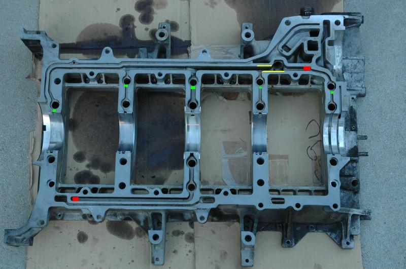
Where your red dye is in the pic I widened that passage all the way to the journal on my girdle and matched it on the block. made it about as wide as the thrust passage next to it. I didn't take any off the gallery passage where your yellow marker is but I can kind of see value in doing that if it results in higher pressure at the entry to the first journal.
10-02-2009, 06:35 PM
#38
I plan to place some marked "buckets", one under each mine, on the floor and see if there's a difference in the flow with nearly zero backpressure. I'll need to find a way to estimate the oil flow to the heads to let those passages flow correctly as well. What's the approximate oil pump flow rate again? I'm going to make a simulation pump with a power steering pump and a variable speed electric motor.
10-03-2009, 01:13 PM
#39
Nordschleife Master
Thread Starter
I plan to place some marked "buckets", one under each mine, on the floor and see if there's a difference in the flow with nearly zero backpressure. I'll need to find a way to estimate the oil flow to the heads to let those passages flow correctly as well. What's the approximate oil pump flow rate again? I'm going to make a simulation pump with a power steering pump and a variable speed electric motor.
Here are some ideas. I have obviously never done anything like that, ever, so these are just off the wall ideas.
- Bolt a plexiglass plate on the top of the girdle.
- Capture the flow on video
- Plug the points that I have marked with green.
- Drill a hole to the plexiglass at the red square to reflect the oil flow to the head, and direct it to bucket with a hose. I have no idea how much oil flows / needs to flow to the heads, so it's a guess.
- Use the bolt holes to direct the oil out of the girdle. It would be nice if you could make restrictors for those bolt holes that you could adjust. The restrictors for mains 1, 2, 4, and 5 should be the same size. The restrictor of main 3 should let more oil thru, but I have no idea by how much.
- Then see how much oil comes out of each the four holes (mains 1, 2, 4, and 5) as you vary the pressure. Also vary the main 3 restrictor size.
Also what would be very interesting is seeing on video what happens when you feed whipped chocolate milk shake aerated oil to the girdle. Does the air and oil separate in a way that just sends more air to #2 main? Instant classic movie.
10-03-2009, 01:30 PM
#40
I completely agree again. I think I'm going to make an adjustable air bleed on the suction side of the pump to let it ingest air at a controlled rate. I'm trying to figure out how to make it seal well because how plexiglass can flex so easy. Yamaha makes a high strength sealer that dries like concrete. Maybe it will seal.
10-03-2009, 01:41 PM
#41
Nordschleife Master
Thread Starter
By the way, speedtalk.com forums had an interesting table posted bySchmidtMotorWorks:
http://speedtalk.com/forum/viewtopic...drill&start=15
For a crank with 2.75" mains like a BBC or 928, the pressure in psi required to overcome centrifugal force is:
@1,000 RPM 0.9psi
@2,000 RPM 3.4psi
@3,000 RPM 7.7psi
@4,000 RPM 13.8psi
@5,000 RPM 21.5psi
@6,000 RPM 30.9psi
@7,000 RPM 42.1psi
@8,000 RPM 55.0psi
@9,000 RPM 69.6psi
@10,000 RPM 85.9psi
@12,000 RPM 123psi
@20,000 RPM 343 psi
This is how much oil pressure the main journal has to see in order for the oil to overcome the centrifugal force and push thru to the middle of the main journal. I am wondering what level of oil pressure the stock engine is seeing in those passages feeding the main bearings?
10-03-2009, 02:15 PM
#43
Nordschleife Master
Thread Starter
See the stock oil paths marked in red:

First, oil needs to be pushed in the middle of the main journal against the centrifugal force. From there, it get's sucked into the rod journals by the centrifugal force. The latter centrifugal force is larger, obviously, because the stroke is much larger than the main journal diameter. If there's no air in the oil and the oil does not cavitate, then there's no problem, because the latter force dominates and sucks oil inside the main journal.
Now, in reality, the oil does cavitate and has air in it. If oil cavitates or has air bubbles in it, then the bubble expands and there really any meaningful sucking effect going on. At least this is how I understood it from Kevin Johnson's explanation. He cited a 1935 patent by Ricardo, by the way, so this is not exactly hot off the press! In this case, the oil pressure from the pump alone must overcome the centrifugal force to push the oil in the middle of the main journal. The table I copied here is the pressure needed in this worst case scenario.
I personally don't see much of a problem with the rod journal drilling from this perspective. If there is oil in the passage in the center of the main journal, the centrifugal force will push it hard out there to the rods. There's no way the centrifugal force associated with moving to an inner orbit in the rod journal can overcome the push the oil gets from moving out 1/2 the stroke from the center of the main journal to the center of the rod journal.
This is, by the way, why Greg Gray is working on inserts to reduce his main journal sizes. That's some advance stuff there he's doing with that engine.
10-03-2009, 02:15 PM
#44
Nordschleife Master
I think the 2/6 bearings fail because they're the closest to the pump.
Once the pump sucks foam or air, it reaches main #2 first and then the following air/foam blows through it. All of the mains are getting fed foam to start, but once it reaches 2/6 the foam goes through there. The other bearings have lost pressure but still have a film in place. The 2/6 bearings get there oil coating air-blasted away.
Sure, it's conjecture, but one things that's certain is that the 2/6 bearings are closest to the pump. If there was a problem with pressure distribution, or available flow, then 2/6 would live and it'd be 4/8 that died.
10-03-2009, 02:27 PM
#45
Nordschleife Master
Thread Starter
I think the 2/6 bearings fail because they're the closest to the pump.
Once the pump sucks foam or air, it reaches main #2 first and then the following air/foam blows through it. All of the mains are getting fed foam to start, but once it reaches 2/6 the foam goes through there. The other bearings have lost pressure but still have a film in place. The 2/6 bearings get there oil coating air-blasted away.
Sure, it's conjecture, but one things that's certain is that the 2/6 bearings are closest to the pump. If there was a problem with pressure distribution, or available flow, then 2/6 would live and it'd be 4/8 that died.
Once the pump sucks foam or air, it reaches main #2 first and then the following air/foam blows through it. All of the mains are getting fed foam to start, but once it reaches 2/6 the foam goes through there. The other bearings have lost pressure but still have a film in place. The 2/6 bearings get there oil coating air-blasted away.
Sure, it's conjecture, but one things that's certain is that the 2/6 bearings are closest to the pump. If there was a problem with pressure distribution, or available flow, then 2/6 would live and it'd be 4/8 that died.
I disagree with one thing, though. If the oil distributing manifold channel has constant cross-sectional area, the exit closest to the pump will see the lowest static pressure.
Suppose that you take a garden hose and plug it in one end and feed water at pressure from the other end. Then, drill same size holes in the garden hose. When you turn the water pressure on, water will first come in from the hole closest to the plugged end and last from the hole closest to the flow source. Furthermore, the far away hole will squirt the oil at high pressure and the near hole will have water barely trickling out. This is because the flow speed is highest in the hose at the near hole and slowest at the far away hole.
The way to remedy this is to reduce the hose size after every hole in away that the flow speed remains constant. This way, the water will flow out at same pressure from all holes.
Perhaps I misundersood what you meant, in that case sorry about my naive lecturing.
The situation in the 928 girdle is exactly analogous. It is inexplicable to me why the cross-sectional area is not larger before the #2 main than after. The flow needs to be slowed down at the #2 main entrance! It looks very much like design error to me, which is very surprising given that those Porsche engineers obviously understand this.