Help Please - Steering rack giving me the shaft!
 03-02-2009, 06:00 PM
#46
Rennlist Member
I'm probably the minority here, but I don't see the need to fiddle with anything except the last u-joint fitting onto the steering rack. The racks are all carefully machined and all the same, the u-joint can only fit one way (+/- a spline, without dremeling), and the factory put the wheel on straight. So if you take out one rack and put in another, why should you need to change anything else?
There are two problems with that theory: One would be if you got a rack that was not indexed correctly, i.e. with the flat not at 9-oclock with the rack centered. If that's fixed then everything else should go back correctly. At worst you will be off one spline at the u-joint which is easily fixed-- just slip it apart, shift it one spline and reasemble.
The other possibility of course is that some PO has been down this road already and things have gotten a bit messed up.
Bill, I am thinking that the wheel is not supposed to be centered when locked. On our '88-- which I am certain has never had the steering wheel off-- the wheels locks at 45-deg left of center.
So if you rotate the steering shaft to lock it, then straighten the wheel, won't the u-joint be off at the rack? I'm confused...
So if you rotate the steering shaft to lock it, then straighten the wheel, won't the u-joint be off at the rack? I'm confused...
Also, if you have the wheel locked in the straight-ahead position, and you are working alone, it is easier to ensure that the rack and wheel are lined up on-center without having to go back and forth between checking the wheel position and fiddling with the U-joint. Aside from making that one assembly step easier, there is no functional reason to recommend that the wheel be in a particular position when the column locks.
Even when I was driving AAA tow trucks in the 80's, we made a point of ensuring that the column was NOT locked when towing from the rear -- we held the wheel on-center via other means -- too many column locks damaged by relying on them while towing. So having it lock on-center is not even useful for that.
 03-02-2009, 06:43 PM
#47
Chronic Tool Dropper
Lifetime Rennlist
Member
Lifetime Rennlist
Member

I'm just dropping in here during frustration moments on my primary project today. I wish that was a simple 928 problem but it isn't.
Rick--
One thing that's sometimes forgotten is that the coupling does not go all the way on to either shaft. It only goes on far enough to get the bolt in through that relief cut in each splined shaft. Same deal on the steering shaft, pinion into the rack. If you try to put it on too far, the bolts won't go in.
Others--
Racks get rebuilt with less than perfect regard for how the pinion and the rack are indexed. There are many possible clocked positions, in fact one for each tooth on the pinion. To get the alignment to work out correctly, the rack needs to be centered or as close as possible to that when the steering wheel is centered and you are going straight down the road. So consider the following sequence of efforts to get the rack in and lined up:
1) Without regard for the steering wheel position or the rack position, engage the coupler to the pinion so the slot for the pinch bolt lines up with the holes in the coupler for the pinch bolt. Install the pinch bolt through that slot, tighten.
2) Without regard for the steering wheel position or the rack position, engage the coupler to the steering wheel shaft so the slot for the pinch bolt lines up with the holes in the coupler for the pinch bolt. Install the pinch bolt through that slot, tighten.
At this point the pinion and the steering wheel are connected and the coupling is snugged so it won't slide off.
3) Pull the plug from the front of the pinion housing. Look inside as you shift the rack left and right to locate the dimple in the rack. Install the rack centering bolt so that the tapered end of that bolt engages the dimple in the rack. The rack is now pinned in its centered position, can't shift because the bolt is holding it in place.
4) Now, take a look at where the steering wheel is facing. There's always the chance that the rack you installed is clocked the same way as the ones that were installed at the factory. A chance. Since we missed that chance, we now need to line the steering wheel up with our centered rack. Remove the horn pad and the nut that hold the steering wheel onto the steering shaft. Follow WSM or tips page directions for this, including care with the horn button wires and with the turn signal combo switch around the cancelling tabs and mechanism. Lift the wheel off the shaft, rotate it so it is straight ahead or as close as possible (less than half a spline from centered), put it back on, put the nut back on and tighten it.
5) Do your preliminary toe setting with tape measure after the car has been lowered and there is weight on the wheels. Use Earl Gillstrom's excellent guide from his member webpage.
6) When you have your toe set correctly for this ride height and centered, only then should you remove the rack centering bolt and put the plug back in. Then go drive the car a few miles and bring it back. Reset the toe-in for your second 'new' ride height with the steering wheel centered. Go drive it for 75 miles, then have it aligned with the steering wheel centered for the final time before lifting the car again for anything. Then drive directly home, MEASURE AND RECORD YOUR RIDE HEIGHT, put the pans and trays back on, ETC.
At this point your rack is centered when the steering wheel is centered while the toe is correct both at center and when the wheel is turned.
03-02-2009, 08:47 PM
#48
Rennlist Member
Thread Starter
Ahhh, the Doctor is IN!!! Thank you Bob, that's the step by step(s) I guess I've been looking for and couldn't find. I knew the coupler didn't go all the way on the shaft and their is some play, but I wasn't positive that the coupler HAD to go on with the bolt hole lined up with the slot(s) in the shaft. Apparently it does!
Thanks to everyone that has basically been saying the same thing and all your tips. I was hoping to get back under the GT and try again tonight, but other "priorities" may not allow me to get back to it until this weekend. I'll let you know how it goes.
One tip I did realize was I thought it would be easiest to install the pressure line "banjo" bolts when everything was still loose, but NOOOOOO, it was actually easier to install them with the rack bolted up tight. Guess the alignment of the banjo bolts is better with the holes in the rack at that point.
03-03-2009, 11:19 AM
#49
Addict
Rennlist Member
Rennlist Member

One addition to Dr Bob's write up: Rick's car is a '90, so, it has an air bag.
On air bag cars, be careful when you pull the steering wheel to adjust position.
1, Always remove the battery ground strap for at least 20 minutes. On later cars, about '93 or later the time was changed to 5 minutes, but don't take any chances. Air bags are VERY dangerous.
2, The air bag is attached with two Torx T30 headed bolts. (Maybe the air bag system was sourced in USA?)
3, If you have to move the wheel very far you may have to re-index the electrical connections by removing the plastic cover and re-indexing the comutator to go through the slot in the wheel. Just slip it off of the splines and rotate until it will fit through the slot in the wheel.
03-03-2009, 12:06 PM
#50
Rennlist Member
Thread Starter
Thanks Earl for the tip. You're correct, I do have an air bag steering wheel. I still need to do a search, I remember someone did a pretty good write up on removing the air bag steering wheel.
03-03-2009, 12:48 PM
#51
Rennlist Member
I am continuing to not understand something. I am not trying to argue with the experts here, I just want to understand a little better.
Dave, thanks for posting the link to your previous rack thread, I read it before and just re-read it. No disagreement with any of that (except perhaps the willingness to accept random re-assembly).
And no argument the rebuilders often (usually) assemble the pinion/control assemblies randomly-- my personal sample is two out of three didn't match the rack coming out (which I believe to be "correct").
I do have a hard time believing that ZF assembles racks randomly, however. (Has anyone had the opportunity to check a number of ZF-rebuilds? Is the flat position consistent with the rack centered?)
I have only one good data point: the original unmolested rack in our 88s4 (owned since new) was at 9-o'clock with the rack centered. The GT was the same, but that rack was a rebuild.
My question/confusion is this: Why screw around with dremels, steering wheels and air-bags when it is simple enough to pull the pinion assembly and re-orient it?
Is there concern about voiding the warranty?
Or is there a concern about safety? Steering is kind of important, and it is possible to screw up the reassembly so that it doesn't turn. But I would think that most folks would notice that before taking off down the highway. I've never considered racks to be any more sacred than any other critical part- suspension, brakes, etc.-- screw-ups are dangerous so don't screw up.
Words of wisdom gratefully welcomed, thanks!!
03-03-2009, 05:28 PM
#52
Rennlist Member
Jim, I didn't want to void the warranty(good thing, the first rack leaked immediately). Also, I didn't know if it was assembled with sealant on the gaskets -- which would mean new gaskets(that I didn't have) if I took it apart. Also I was concerned about parts flying out and hiding if I took it apart. So I'm sure that once you've had it apart and looked at all of the pieces and put it back together one time, re-clocking the pinion seems like an easy approach.
I would ask you though -- what guarantee do you have that that will always give you the same result? The spline is pinned to the input shaft. Is there any guarantee that, if the spline were replaced, it would be drilled the same and line up perfectly as expected? I don't know, but there were so many unknowns I just dealt with it in my own way.
Bob's steps above are perfectly OK for anyone who doesn't care about whether the steering wheel locks in a straight ahead position, or doesn't mind adjusting for a half-spline misalignment by adjusting the tie rod ends. When I had it all together everything was dead-nuts centered, no half-spline crap. The car was aligned with the centering bolt in place, which also gives me a perfectly centered wheel.
Just as some of you are baffled that I would care about having the wheel lock in a straight-ahead position, I am baffled that only Dave C(other thread) and myself seem to care about it. Whatever, as I said before, there is no functional, "engineering" type reason why it ought to be in any particular position. Even having the wheel straight when going straight down the road is just a matter of preference(though much more of an "expected" behavior) with no functional, "engineering" type justification to it. I'm sure that those with the yellow tape on the tops of their racing wheels would argue the point though.
Anyway, here I am on the other side of the issue for a change -- I did the job in a way that gave me the results I wanted, and everyone else is on the other side, wringing their hands that I didn't do it the "Porsche" way. That's OK. I'm happy with the results.
03-03-2009, 07:16 PM
#53
Under the Lift
Lifetime Rennlist
Member
Lifetime Rennlist
Member
The two ZF rebuilds I have used had the pinion installed "correctly" and did not require any modification to get the steering wheel and rack centered.
03-04-2009, 01:32 AM
#54
Rennlist Member
Thread Starter
Jim (or anyone else who knows), just to confirm, when you say set at 9-o'clock, you mean the "notch" is facing 9-o'clock? Which way are you viewing it? If typical, and you are looking at it from the drivers seat, 9-o'clock would have the notch facing the left/drivers side of the car?
03-04-2009, 02:58 AM
#55
Rennlist Member
Yep, what you said here:
Keep in mind that there is no assurance that yours wants to be oriented the same way, much is unknown including whatever a PO might have done. There are many options, none wrong.
How's progress?
How's progress?
03-04-2009, 11:04 AM
#56
Rennlist Member
Thread Starter
Thanks Jim. I was more curious than anything. I want to compare the rack I took out with the new/rebuilt one. Never know, I might get lucky... Wouldn't have a problem reorienting the shaft, but wouldn't want to void any warranty, so I'll be using the good Dr. Bob's method mentioned above.
No more progress yet, thought I might be able to work on it this week during the evenings, but work and other committments have conspired to make me hold off until Saturday again.
No more progress yet, thought I might be able to work on it this week during the evenings, but work and other committments have conspired to make me hold off until Saturday again.
03-04-2009, 02:07 PM
#57
Rennlist Member
BTW, before grinding on the shaft, I checked with the supplier -- Jim Bailey assured me that grinding the shaft would not void the warranty, since the spline portion was replaceable.
03-04-2009, 04:50 PM
#58
Rennlist Member
Thread Starter
Jim, I know you've described it, but is "re-clocking" the pinion shaft really that big a deal. It doesn't sound that difficult, UNLESS as Dave pointed out that the gasket(s) would have sealant on them. Would this be normal (for the gaskets to have sealant on them)? Is there power steering fluid in this location?
IF the notch on the rack shaft is not indexed where it's supposed to be, I would think it might be easier for me to adjust it back to where it's supposed to be rather than mess with my air bag steering wheel.
Anyone want to comment?
IF the notch on the rack shaft is not indexed where it's supposed to be, I would think it might be easier for me to adjust it back to where it's supposed to be rather than mess with my air bag steering wheel.
Anyone want to comment?
03-04-2009, 05:41 PM
#59
Rennlist Member
Rick, I don't know if sealant was used on the gaskets. Not knowing, I didn't want to find out the hard way. You should be able to guesstimate the approximate location of the notch on yours prior to disassembly by centering the wheel and looking at where the pinch bolt is oriented.
03-04-2009, 07:37 PM
#60
Rennlist Member
Jim, I know you've described it, but is "re-clocking" the pinion shaft really that big a deal. It doesn't sound that difficult, UNLESS as Dave pointed out that the gasket(s) would have sealant on them. Would this be normal (for the gaskets to have sealant on them)? Is there power steering fluid in this location?
IF the notch on the rack shaft is not indexed where it's supposed to be, I would think it might be easier for me to adjust it back to where it's supposed to be rather than mess with my air bag steering wheel.
Anyone want to comment?
IF the notch on the rack shaft is not indexed where it's supposed to be, I would think it might be easier for me to adjust it back to where it's supposed to be rather than mess with my air bag steering wheel.
Anyone want to comment?
Here's some more details and a couple of pictures of what is in there, this might make your choice easier.
I wouldn't think that fixing a mis-indexed pinion would void a warranty, but you might check with your supplier to be sure. I also didn't find any sealant, so as a practical matter there is no way to tell that it has been apart (again).
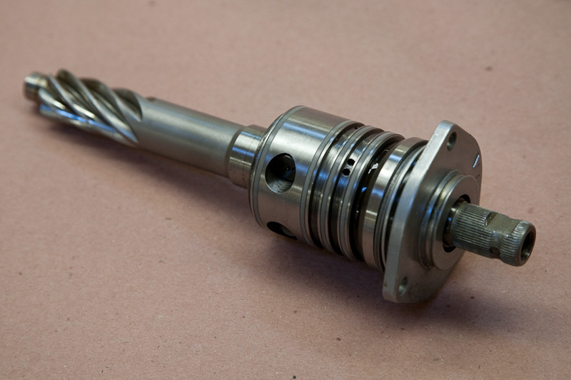
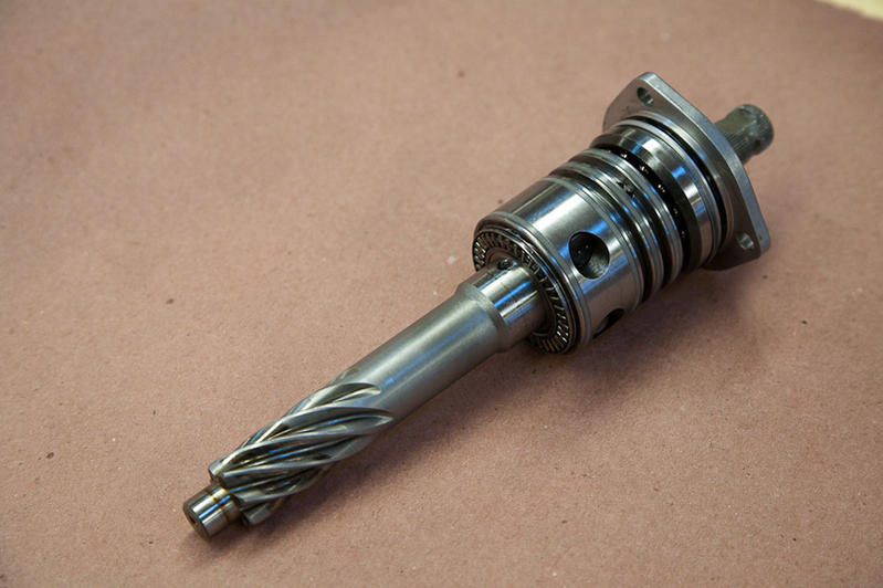
The pinion-shaft/control-valve assembly is shown below. Starting from the left (towards front of car, as installed) you've got a small bearing surface that fits into a small roller bearing pressed into the housing; the pinion-gear that engages the rack; a flat thrust-bearing; the control-valve assembly (the fat part) with some o-rings; a ball-bearing; a shim, and the cover-plate with an o-ring and a shaft-seal.
The first thing to do (with the rack out and disconnected of course) is take the pressure off of the pinion. The rack is held in contact with the pinion by a guide-block and spring, located underneath the steel cap on the bottom of the rack. Loosen those two 13mm-headed bolts to relieve the spring pressure, you can also remove them and remove the cap, spring and shim-washer. Beyond that is the backside of the guide-block. There should be no hydraulic fluid around the rack and there is an o-ring around the guide block in any case (which is why it will not willingly come out of its bore). The rack will now have some "wiggle room" to get the pinion in and out easily.
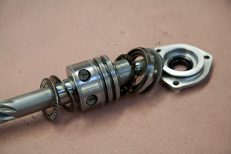
Now remove the three 10mm-headed bolts securing the cover plate. Note the orientation of the flat (notch) in the shaft, and the arrow on the cover-plate for re-assembly. (I don't think the cover orientation matters but we're all obsessive). Rotate the cover enough to get your fingers under the "ears" and gently lift- there is an o-ring under the cover which will gently resist. Stifle the urge to stick a screwdriver in and pry, but a small plastic mallet might help if it is stubborn. Or grab the stub-shaft with pliers (and a couple small pieces of wood to protect the splines) and pull the shaft.
You want the whole assembly to come out together if possible, to avoid any chance of the shaft-seal getting chewed by any rough edges on the splines. Everything between the cover o-ring and the last nylon ring is hydraulics, keep it clean. (Butcher paper is great to have around to make dirty benches into clean ones).
Check for the thrust-bearing. It has two races (flat washers), one will stay behind in the housing and the other usually follows the control-assembly out. Those are outside the hydraulic area, add a little fresh grease (clean wheel-bearing grease) if needed to persuade them to stay in place for reassembly.
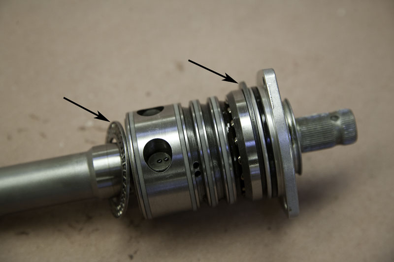
The shaft twisted as it came out, add that to how far to reorient it and then re-assemble. Then slide it back together. It should slide all the way home with a bit of wiggle and gentle persuation for the o-rings, if it hangs up don't force it. There are two parts that might want to catch during reassembly-- that thrust-bearing at the pinion end, and the shim-washer under the cover (see arrows in the last picture). Just be sure they are centered and not sticking out as they are in the picture.
Be sure the cover is fully seated and properly oriented, check the flat/notch position, repeat the above steps as needed, and make sure the shaft turns freely (with some o-ring resistance). Install and torque the three cover screws. Re-install the spring, shim-washer and cover (if removed) and torque those two bolts. I used the generic 6 ft-lbs for the little cover-bolts and 15 for the cover-plate.
That's it, hope you don't need it!