
Converting a 928 to Megasquirt. (LONG)
 12-08-2008, 08:51 PM
#31
Nordschleife Master
Thread Starter
Step 2 of MS install, wiring.
This is the most labour intensive portion of the project, but is the single most important part.
Keep in mind that ALL joints that are made should be soldered and sealed with heatshrink tubing (preferably the style with internal glue).
I would recommend using connectors with pigtails for all the sensors/connectors, but this is not mandatory.
To start the easiest way is to remove the factory EFI harness from the car (non CIS). Then mount the MS unit where you would like it to be. The stock location works well.
Once it is mounted you will need to take the 12’ MS ready harness that you purchased and split the shielding right near the connector. You will draw the O2, Grounds, and fuel pump lines out of the harness close to the connector. You will also need to remove a part of the power lead from the harness, I would recommend cutting it. The portion going to the MS will power it, the wire left in the loom will power the + side of the injectors, I would recommend adding a fuse to this wire. I would then recommend that you get the firewall boot (non CIS) off the original harness, this is easiest to simply cut the harness in half. Once off put this back into the car sans wires. Then take the 12’ loom and feed the main wires (not the ones you pulled out of the sheath), through the grommet and into the engine bay bringing them up onto the top of the engine. Plug the harness into the MS so that it is held in place and will not end up too short or long. Once this is done the next step will be mounting the EDIS components and wiring up the engine bay. So you need to first find a location to mount the EDIS-8 control module, and coils, I will assume that you already have the trigger wheel and VR sensor mounted. This is important to decide the FINAL mounting place for these items before you start wiring. If you have a 16V and decide to mount the throttlebody on the rear of the center plenum, then in the engine V is a decent place to hide the coils.
Now for running the factory coil you do not need to mount anything extra and wiring is a little different. So I will start with what is the same.
First will be injectors, now there are 2 injector bank wires marked INJ1 and INJ2 on the wires. If you are wanting to get the absolutely best idle you can then look at the firing order and run INJ1 to 1, 4, 6,7 and INJ2 to 5, 2, 3, 8. If you notice this is every other injector from the firing order on one lead. If having a dead perfect idle (but still VERY good, and probably better than stock) is ok then on INJ1 run one bank of the engine, and INJ2 for the other bank of the engine. The latter option is still very good and cuts down on a lot of imo needless complications. So to do this you will split the harness in the engine bay and find the wires INJ1 and INJ2, you will then lay them over the fuel rails. Then take the fuel injector connectors and put them on the injectors and attach the - wire from the injector connectors to the INJ1/2 wires. This is one of the reasons I recommend the pigtails as they have a red and a black wire for them and it is easy to follow. Next is to complete the + side of the injector, this needs to be a switched + wire, and as mentioned earlier you will use the power lead that cam in the loom. However this wire only goes to one bank, if you wish to add another + wire all the way into the interior compartment you can, but it is not required. I shaved off some insulation and soldered on another red wire to it. I then had one of the leads running up one bank, and the other on the other bank and connected the + lead from the pigtails to this wire.
Now that your injectors are done we will find the wire that says CLT and run it up with the passenger side fuel injector wires. You will attach this wire to the CLT sensor, the other pin on the CLT (and IAT) sensor goes to ground which is why I recommend it with the pigtail. It is just long enough to attach to a close ground. Or extend and put all at the same ground locations either works. Next is the IAT sensor, and again you have to decide where it goes, but I put mine in the air box. So it was easy to just drape the lead onto the drivers side injectors and give myself lots of room so I could lift the box a long way before having to disconnect the sensor. And again the second lead goes to ground, I used one of the 2 bolt holes on the back of the engine.
Next will be the TPS, there are 2 wires coming from the MS to this, and one of its wires will go to ground. You will have to figure out which wire is which on your setup, and TPS.
The next is connecting the EDIS, some of this will be to the MS harness some of it will be connecting its components back together. Now there are a couple of pictures to help with this
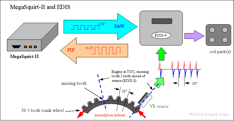
looking over this you actually want the missing tooth 5 teeth (8 cyl) ahead of the VR sensor. This shows how it corresponds to the MS unit and its connectors to it.
The only other image one should need for connecting the setup follows.
This shows which wires need to connect to what.
Now at this time I did add one more wire to the loom, I put it back into the interior. This wire is to turn on the EDIS-8 and it goes to pin #6 of the EDIS-8 module. I ran this off the EZF relay, again fusing it is a good idea. If I need to give you a full break down on how to connect these wires for the EDIS at this point, you may be getting into something over your head, or need to revisit this as you are actually putting it together.
Now after thinking about this and how it is hooked up and just looking at one of the 12’ looms I see it only has one shielded wire. I am not pretty sure I added a second shielded wire to the loom for the SAW line as I didn’t want to have to try and fight with any RF instabilities. As well I added another wire (more used one that I wasn’t using and disconnected it from the loom near the connector to connect to pin #2 of the EDIS-8 module for the Tach output, which is not shown on that diagram.
Now if you are not doing EDIS and are going with a distributor pickup/coil then you need to hook it up now. The pickup in our distributors are of the HALL sensor variety (correct me if I am wrong on this but I am 97% certain I am correct)
So for the hall connector on the distributor you have 2 wires, one will go to pin #24 to the MS, the other wire going into the hall sensor should be a switched positive. Again this is not the preferred method of doing this and I haven’t set one up this way so it is best to follow the manual on this found here. However once that is wired, you should have another wire which will go to one side of the coil (normally the negative side). For the tachometer you will tap into this - line near the MS connector and attach to the CE panel connector later. You may need to add a wire to supply current to the + side of the coil, if doing this I would recommend that you MAKE SURE it has voltage while cranking, and use the factory resistor so as not to heat the coil up too much.
Please note that there are MANY reasons I recommend EDIS, and one of the biggest ones being that with EDIS you do not have to worry about setting/adjusting dwell times and other parameters which can lead to failed coils and problems down the road which will leave one frustrated with the setup when is it simply not setup correctly.
That is where I will pretty much end all of my help with the distributor setups as I have limited experience with them, though if you run into a snag with your setup and doing this, I would be more that willing to attempt to help you decipher the information out there.
This should conclude the engine bay wiring portion of the installation.
Now comes the fun.
Go back to the harness you took out of the car and cut off (with long pigtails), the fuse panel connector. This is where it can get tricky and I recommend you have the wiring diagrams in PDF form so you can print them up and also zoom in on certain areas to be able to decipher them. You will need to know what pins on that connector go where, I found it easiest as I knew what went there to start at those points. So I started from the fuel pump relay and traced the wires, same with the LH, EZF, tach line etc. Now armed with those pieces of info it is pretty straight forward, wire the + line of the MS to the switched lead which comes from the LH, and then add that wire coming from the EDIS to the EZF. And the wire from pin 2 of the EDIS to the tach input wire. You will now need to hook up the fuel pump wire to the switching wire for the FPR, now keep in mind that the MS system switches the relay using the negative, I cannot remember how the factory switches it, but I do know that I had to change the + switched wire on the back of the CE panel, I tagged into a switched +12V wire right beside it and it works well. Now there should also be (iirc) a wire in there for the O2 heater circuit. You will need to now get the WB O2 sensor and use this to supply the +12V to it. You will also connect the WB output line to the O2 line you brought out of the loom earlier. Once everything else is taken care of do the grounds. But for the grounds, you must take one step, you MUST solder the – line for the WB to one of the ground lines for the MS box. If you do not do this then you could get variances between readings that the WB puts out and what the MS actually reads.
There is only one other picture which will help greatly with wiring

This should be all of the wiring taken care of, if I missed something please let me know as it has been almost 2 years since I did my install
End of wiring, next will be starting the MS system.
This is the most labour intensive portion of the project, but is the single most important part.
Keep in mind that ALL joints that are made should be soldered and sealed with heatshrink tubing (preferably the style with internal glue).
I would recommend using connectors with pigtails for all the sensors/connectors, but this is not mandatory.
To start the easiest way is to remove the factory EFI harness from the car (non CIS). Then mount the MS unit where you would like it to be. The stock location works well.
Once it is mounted you will need to take the 12’ MS ready harness that you purchased and split the shielding right near the connector. You will draw the O2, Grounds, and fuel pump lines out of the harness close to the connector. You will also need to remove a part of the power lead from the harness, I would recommend cutting it. The portion going to the MS will power it, the wire left in the loom will power the + side of the injectors, I would recommend adding a fuse to this wire. I would then recommend that you get the firewall boot (non CIS) off the original harness, this is easiest to simply cut the harness in half. Once off put this back into the car sans wires. Then take the 12’ loom and feed the main wires (not the ones you pulled out of the sheath), through the grommet and into the engine bay bringing them up onto the top of the engine. Plug the harness into the MS so that it is held in place and will not end up too short or long. Once this is done the next step will be mounting the EDIS components and wiring up the engine bay. So you need to first find a location to mount the EDIS-8 control module, and coils, I will assume that you already have the trigger wheel and VR sensor mounted. This is important to decide the FINAL mounting place for these items before you start wiring. If you have a 16V and decide to mount the throttlebody on the rear of the center plenum, then in the engine V is a decent place to hide the coils.
Now for running the factory coil you do not need to mount anything extra and wiring is a little different. So I will start with what is the same.
First will be injectors, now there are 2 injector bank wires marked INJ1 and INJ2 on the wires. If you are wanting to get the absolutely best idle you can then look at the firing order and run INJ1 to 1, 4, 6,7 and INJ2 to 5, 2, 3, 8. If you notice this is every other injector from the firing order on one lead. If having a dead perfect idle (but still VERY good, and probably better than stock) is ok then on INJ1 run one bank of the engine, and INJ2 for the other bank of the engine. The latter option is still very good and cuts down on a lot of imo needless complications. So to do this you will split the harness in the engine bay and find the wires INJ1 and INJ2, you will then lay them over the fuel rails. Then take the fuel injector connectors and put them on the injectors and attach the - wire from the injector connectors to the INJ1/2 wires. This is one of the reasons I recommend the pigtails as they have a red and a black wire for them and it is easy to follow. Next is to complete the + side of the injector, this needs to be a switched + wire, and as mentioned earlier you will use the power lead that cam in the loom. However this wire only goes to one bank, if you wish to add another + wire all the way into the interior compartment you can, but it is not required. I shaved off some insulation and soldered on another red wire to it. I then had one of the leads running up one bank, and the other on the other bank and connected the + lead from the pigtails to this wire.
Now that your injectors are done we will find the wire that says CLT and run it up with the passenger side fuel injector wires. You will attach this wire to the CLT sensor, the other pin on the CLT (and IAT) sensor goes to ground which is why I recommend it with the pigtail. It is just long enough to attach to a close ground. Or extend and put all at the same ground locations either works. Next is the IAT sensor, and again you have to decide where it goes, but I put mine in the air box. So it was easy to just drape the lead onto the drivers side injectors and give myself lots of room so I could lift the box a long way before having to disconnect the sensor. And again the second lead goes to ground, I used one of the 2 bolt holes on the back of the engine.
Next will be the TPS, there are 2 wires coming from the MS to this, and one of its wires will go to ground. You will have to figure out which wire is which on your setup, and TPS.
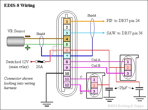
The next is connecting the EDIS, some of this will be to the MS harness some of it will be connecting its components back together. Now there are a couple of pictures to help with this
looking over this you actually want the missing tooth 5 teeth (8 cyl) ahead of the VR sensor. This shows how it corresponds to the MS unit and its connectors to it.
The only other image one should need for connecting the setup follows.
This shows which wires need to connect to what.
Now at this time I did add one more wire to the loom, I put it back into the interior. This wire is to turn on the EDIS-8 and it goes to pin #6 of the EDIS-8 module. I ran this off the EZF relay, again fusing it is a good idea. If I need to give you a full break down on how to connect these wires for the EDIS at this point, you may be getting into something over your head, or need to revisit this as you are actually putting it together.
Now after thinking about this and how it is hooked up and just looking at one of the 12’ looms I see it only has one shielded wire. I am not pretty sure I added a second shielded wire to the loom for the SAW line as I didn’t want to have to try and fight with any RF instabilities. As well I added another wire (more used one that I wasn’t using and disconnected it from the loom near the connector to connect to pin #2 of the EDIS-8 module for the Tach output, which is not shown on that diagram.
Now if you are not doing EDIS and are going with a distributor pickup/coil then you need to hook it up now. The pickup in our distributors are of the HALL sensor variety (correct me if I am wrong on this but I am 97% certain I am correct)
So for the hall connector on the distributor you have 2 wires, one will go to pin #24 to the MS, the other wire going into the hall sensor should be a switched positive. Again this is not the preferred method of doing this and I haven’t set one up this way so it is best to follow the manual on this found here. However once that is wired, you should have another wire which will go to one side of the coil (normally the negative side). For the tachometer you will tap into this - line near the MS connector and attach to the CE panel connector later. You may need to add a wire to supply current to the + side of the coil, if doing this I would recommend that you MAKE SURE it has voltage while cranking, and use the factory resistor so as not to heat the coil up too much.
Please note that there are MANY reasons I recommend EDIS, and one of the biggest ones being that with EDIS you do not have to worry about setting/adjusting dwell times and other parameters which can lead to failed coils and problems down the road which will leave one frustrated with the setup when is it simply not setup correctly.
That is where I will pretty much end all of my help with the distributor setups as I have limited experience with them, though if you run into a snag with your setup and doing this, I would be more that willing to attempt to help you decipher the information out there.
This should conclude the engine bay wiring portion of the installation.
Now comes the fun.
Go back to the harness you took out of the car and cut off (with long pigtails), the fuse panel connector. This is where it can get tricky and I recommend you have the wiring diagrams in PDF form so you can print them up and also zoom in on certain areas to be able to decipher them. You will need to know what pins on that connector go where, I found it easiest as I knew what went there to start at those points. So I started from the fuel pump relay and traced the wires, same with the LH, EZF, tach line etc. Now armed with those pieces of info it is pretty straight forward, wire the + line of the MS to the switched lead which comes from the LH, and then add that wire coming from the EDIS to the EZF. And the wire from pin 2 of the EDIS to the tach input wire. You will now need to hook up the fuel pump wire to the switching wire for the FPR, now keep in mind that the MS system switches the relay using the negative, I cannot remember how the factory switches it, but I do know that I had to change the + switched wire on the back of the CE panel, I tagged into a switched +12V wire right beside it and it works well. Now there should also be (iirc) a wire in there for the O2 heater circuit. You will need to now get the WB O2 sensor and use this to supply the +12V to it. You will also connect the WB output line to the O2 line you brought out of the loom earlier. Once everything else is taken care of do the grounds. But for the grounds, you must take one step, you MUST solder the – line for the WB to one of the ground lines for the MS box. If you do not do this then you could get variances between readings that the WB puts out and what the MS actually reads.
There is only one other picture which will help greatly with wiring
This should be all of the wiring taken care of, if I missed something please let me know as it has been almost 2 years since I did my install
End of wiring, next will be starting the MS system.
 12-08-2008, 11:34 PM
#32
Rennlist Member
Join Date: Dec 2002
Posts: 1,051
Likes: 0
Received 0 Likes
on
0 Posts
As for cost, a few years back when I was in touch with him, the owner of that car told me he had less than $100 in the ECU, sensors, and connectors. The throttle body, with the TPS and idle air controller on it, he got for $60.
The one in the distributor is a variable reluctance sensor, not a Hall sensor.
12-08-2008, 11:38 PM
#33
Nordschleife Master
Thread Starter
Thanks for the correction on the dizzy pickup Z, and I remembered seeing that car a long time ago, and that is what I was refering to on the TB setup on the manifold.
12-08-2008, 11:42 PM
#34

Back to trying to find someone who will weld aluminum... inexpensively.
12-08-2008, 11:44 PM
#35
Nordschleife Master
Thread Starter
Brendan, if you are talking about the TB install to a 16v center plenum, get the plate cut and send it and a plenum to me, I will weld it up and open the hole up with my plasma cutter for you, or I could get one of the plenums locally and do it myself, then ship it and just send you a bill 
12-09-2008, 01:46 AM
#36
Would it be worth extra power?
I mean, it LOOKS cool.

I mean, it LOOKS cool.
12-09-2008, 03:59 AM
#37
Nordschleife Master
Thread Starter
It depends on what is done with the rest of the system but this over the stock throttlebody with AFM or CIS metering plate YES, it would be good for some power gains. And those throttle bodies can be had very cheaply. Do you want me to try to find one locally?
12-09-2008, 06:15 PM
#38
Colin:
http://cgi.ebay.com/ebaymotors/Elect...QQcmdZViewItem
These have metric threads. I know GM sensors are usually used, but what about these?
http://cgi.ebay.com/ebaymotors/Elect...QQcmdZViewItem
These have metric threads. I know GM sensors are usually used, but what about these?
12-09-2008, 07:43 PM
#39
Nordschleife Master
Thread Starter
seeing as how it has the temp chart with resistance ranges YES those could be used without any issues. Though you would need to confirm the threads are the same as OE
12-12-2008, 02:55 AM
#41
Nordschleife Master
Thread Starter
in my 86.5 I have a MAF still in there, as I havent been bothered to replace it. It worked last I tried too lol. I have removed it and tested other cars with it too.
01-02-2009, 08:49 PM
#42
Racer

Join Date: Jul 2008
Location: south shore MA
Posts: 363
Likes: 0
Received 0 Likes
on
0 Posts
I have got my MS-II kit ordered and I and going to convert my 84 Euro to MS. I have allready converted my 98 dr 350 dual sport motorcycle to MS so I think I should not have too many problems. I am doing this the get away from very high EFI related replacement parts cost. In the process I am going to convert to a EDIS ignition system. Also I will be able to replace the mechanical fan with a temperature controled electric fan. On top of that I will be able to implement a fast idle set up, nice. I think MS will bring my 84 euro into the 21st century.
01-13-2009, 01:35 PM
#44
Nordschleife Master
Thread Starter
Hessank,
Thanks for bringing this back up, I haad forgotten about it
there are outputs from MS that you can use to control pretty much anything you want and you can set it up how you want.
However that said. Unless I was living in Kali I would not even consider using the stock S4 intake manifold with how restrictive it is. I would make a new much simpler intake manifold as I see that there is alot of power to be had from that.
01-13-2009, 04:11 PM
#45
Chronic Tool Dropper
Lifetime Rennlist
Member
Lifetime Rennlist
Member

I'm pretty sure I could get ITB's to pass muster here in California if it had a nice black opaque plastic plenum cover with "Porsche" lettering molded in. Seriously. Add-on stuff really needs to have an original 20-year-old look to it, and 12-digit Porsche or Bosch part numbers and names. After that it's not even a mild sales job. Anything with bling or that custom-fab'd look is out. Dusty and oxidized is a snap.
Just sayin'...
Just sayin'...