
Rear Caliper Refurbish ('84) with pics
 05-26-2008, 10:19 AM
#1
Three Wheelin'
Thread Starter
Join Date: Sep 2007
Location: Ridgecrest, California
Posts: 1,363
Likes: 0
Received 146 Likes
on
30 Posts
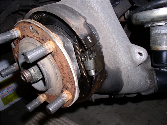
Recently, I was experiencing a scraping sound coming from the rear passenger side wheel of the '84. I took the wheels off but could not see or hear the noise. Put the wheels back on and there it was again. I feared something was wrong with the emergency brake or brake pads. I had always planned to rebuild and clean up the rear brakes since I went through the front suspension and brakes several months ago so I figured now was as good a time as any.
I had never rebuilt the rear brakes before so I took a few pics along the way to share with other Noobs like myself. This post is long but hopefully others will find is helpful.
First, here's a list of the parts and tools I used for the job:
1. 11mm, 13mm, 14mm, 17mm, 19mm combination wrenches
2. 10mm, 19mm (or 3/4") sockets
3. 6mm allen socket (or allen wrench)
4. Phillips screwdriver, Flat blade screwdriver
5. Regular pliers, spring clip pliers
6. Punch and small hammer
7. 2 small "C" clamps, 1 large 6" "C" clamp
8. Several quart size plastic baggies
9. Small pick
10. Micrometer
11. Painter's Tape
12. Caliper paint and clear coat
13. Silicone Lube and brake caliper grease
14. Brake cleaner
15. Disk Brake Quiet
16. Air compressor and vacuum pump
17. Brake Fluid
18. Set of Rear Brake Pads
19. 2 Rear Caliper Rebuild kits
20. 2 Rear Brake Rotors
21. 2 Rear Brake Hoses (I used stainless steel lines)
Start by blocking the front wheels, loosening the rear wheel lugs, lifting the rear end of the car and supporting on suitable jack stands, and removing the rear wheels. Here's where I start the disassembly
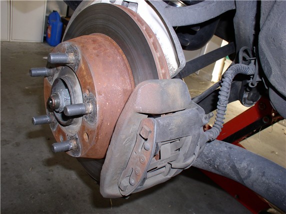
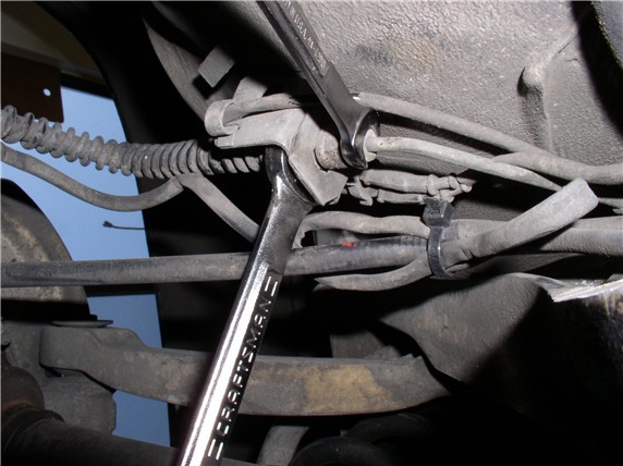
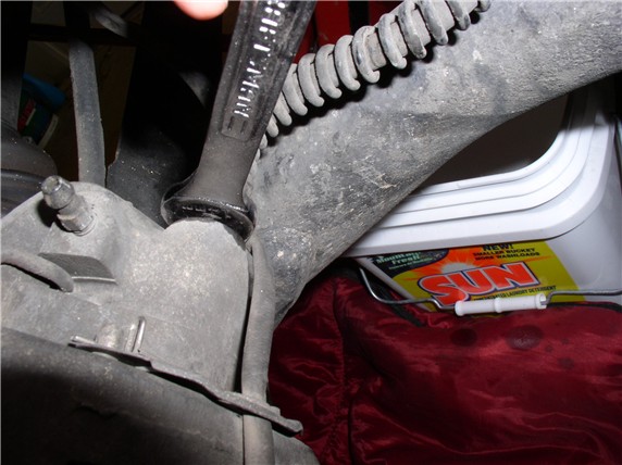
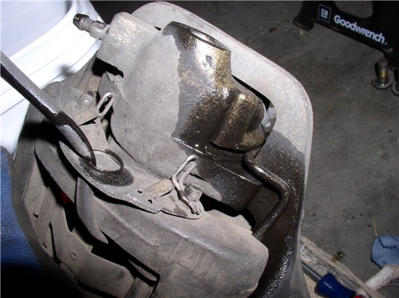
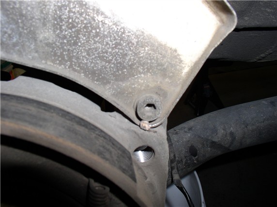
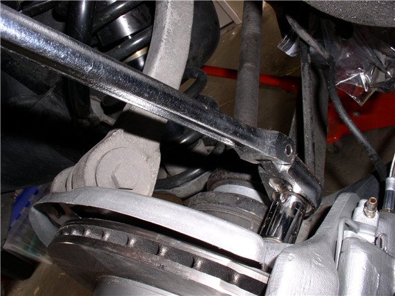
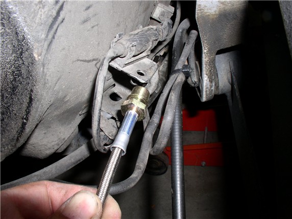
First, disconnect the brake line at the juction where the steel brake line meets with the brake hose to the caliper. Get a bucket or drain pan to catch dripping brake fluid. You will need the 11mm and 17mm combination wrenches. Use the 17mm to counterhold the large nut on the brake hose.
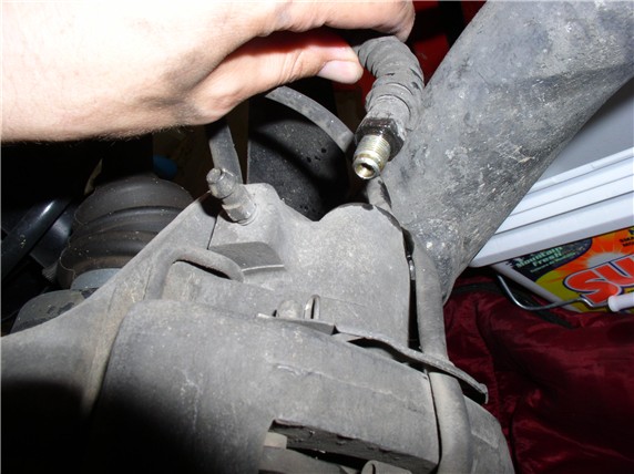
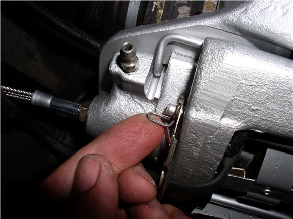
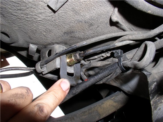
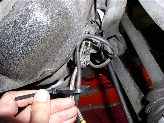
You can now remove the clip that secures the brake hose to the body. Use a flat blade screwdriver to initially pry away the clip. If more help is needed, use pliers to pull the clip out.
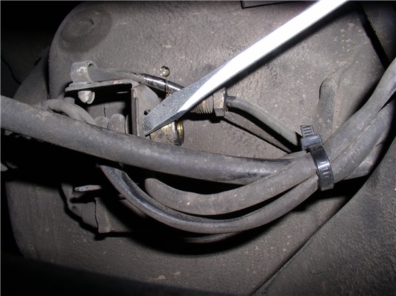
Now you can pull the brake hose away from the body mount.
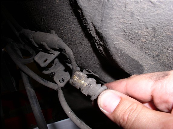
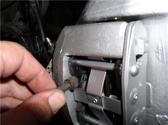
Use a 14mm combination wrench to disconnect the brake hose from the caliper.
Continued.....
I had never rebuilt the rear brakes before so I took a few pics along the way to share with other Noobs like myself. This post is long but hopefully others will find is helpful.
First, here's a list of the parts and tools I used for the job:
1. 11mm, 13mm, 14mm, 17mm, 19mm combination wrenches
2. 10mm, 19mm (or 3/4") sockets
3. 6mm allen socket (or allen wrench)
4. Phillips screwdriver, Flat blade screwdriver
5. Regular pliers, spring clip pliers
6. Punch and small hammer
7. 2 small "C" clamps, 1 large 6" "C" clamp
8. Several quart size plastic baggies
9. Small pick
10. Micrometer
11. Painter's Tape
12. Caliper paint and clear coat
13. Silicone Lube and brake caliper grease
14. Brake cleaner
15. Disk Brake Quiet
16. Air compressor and vacuum pump
17. Brake Fluid
18. Set of Rear Brake Pads
19. 2 Rear Caliper Rebuild kits
20. 2 Rear Brake Rotors
21. 2 Rear Brake Hoses (I used stainless steel lines)
Start by blocking the front wheels, loosening the rear wheel lugs, lifting the rear end of the car and supporting on suitable jack stands, and removing the rear wheels. Here's where I start the disassembly
First, disconnect the brake line at the juction where the steel brake line meets with the brake hose to the caliper. Get a bucket or drain pan to catch dripping brake fluid. You will need the 11mm and 17mm combination wrenches. Use the 17mm to counterhold the large nut on the brake hose.
You can now remove the clip that secures the brake hose to the body. Use a flat blade screwdriver to initially pry away the clip. If more help is needed, use pliers to pull the clip out.
Now you can pull the brake hose away from the body mount.
Use a 14mm combination wrench to disconnect the brake hose from the caliper.
Continued.....
 05-26-2008, 10:59 AM
#2
Three Wheelin'
Thread Starter
Join Date: Sep 2007
Location: Ridgecrest, California
Posts: 1,363
Likes: 0
Received 146 Likes
on
30 Posts
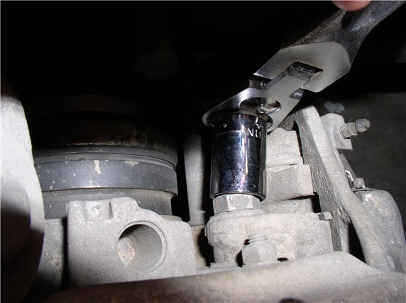
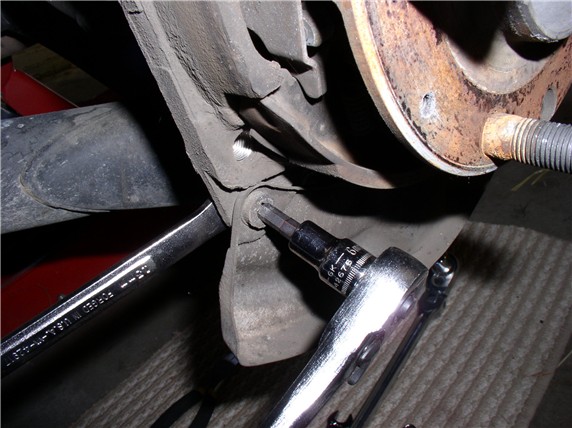
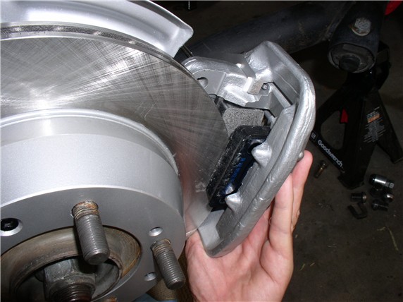
Next, use a 19mm (or 3/4") socket to take off the caliper bolts. There are two, one on top and one on the bottom. I used a socket to the the one on the top and a combo wrench to get to the one on the bottom because of clearance.
At this point, you can remove the caliper from the rotor. However, the brake pad sensor should still be attached.
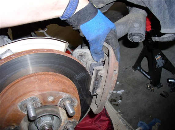
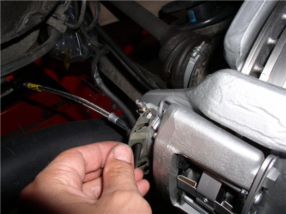
To remove the brake pad sensor, you need to remove the sensor wire holder. Use a pair of pliers to remove the 2 retaining pins and the holder will slide off the retaining pins. Then, gently pull the wear sensor from the brake pad.
Now the caliper with pads should be free.
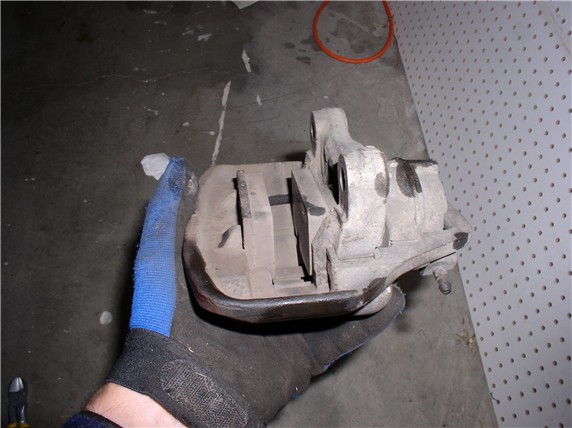
Set the caliper on a work surface and plug the brake line hole. I used a shop paper towel.
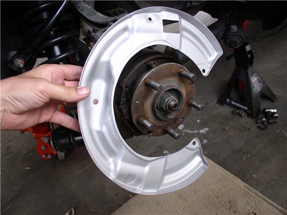
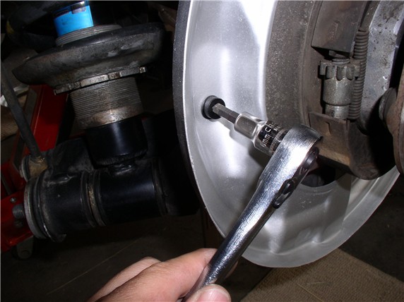
Next, you can take off the rotor. Use a large phillips screwdriver (or impact driver) to take the 2 screws out.
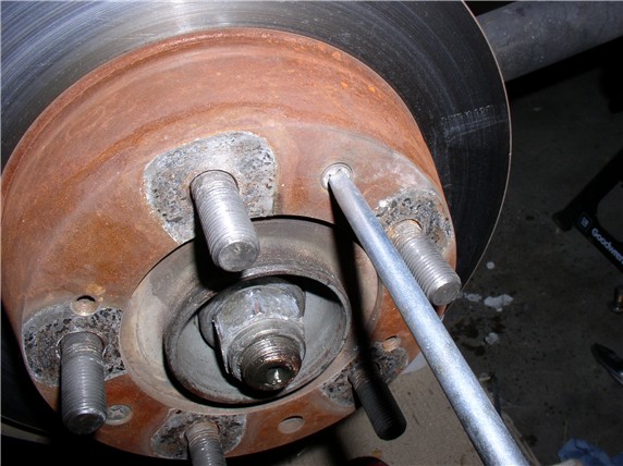
The rotor will come off after the 2 screws are out.
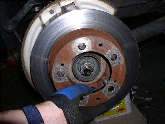
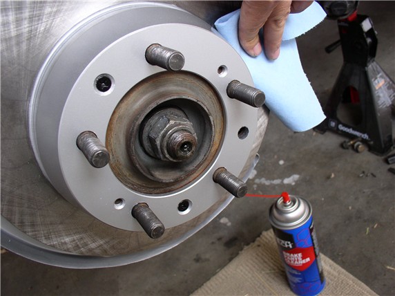
At this point, I discovered what was causing the scraping. A small pebble had jammed between the rotor shield and rotor.
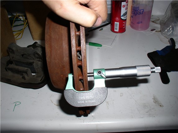
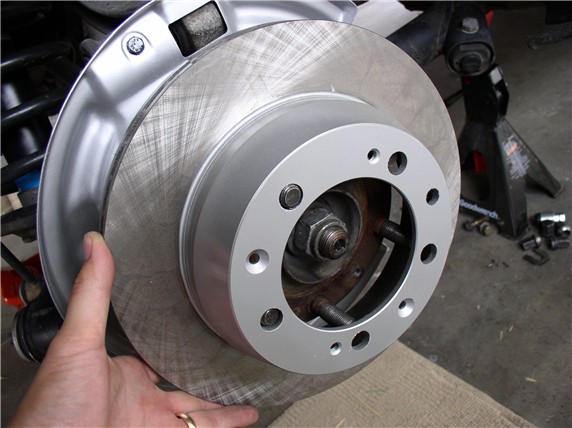
Now you can measure the thickness of the rotor with a micrometer. Mine turned out to be about 19.7mm. New disk thickness is 20mm. Very little wear on my old ones. Wear limit is 18.6mm.
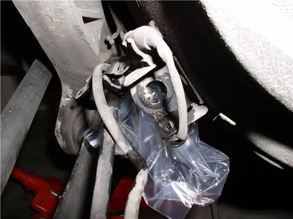
Place a baggie over the exposed brake line to prevent dirt from getting on the connection or inside the line.
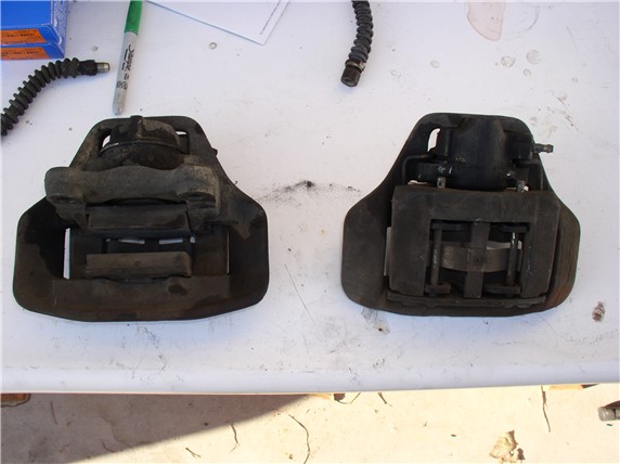
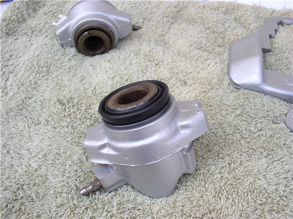
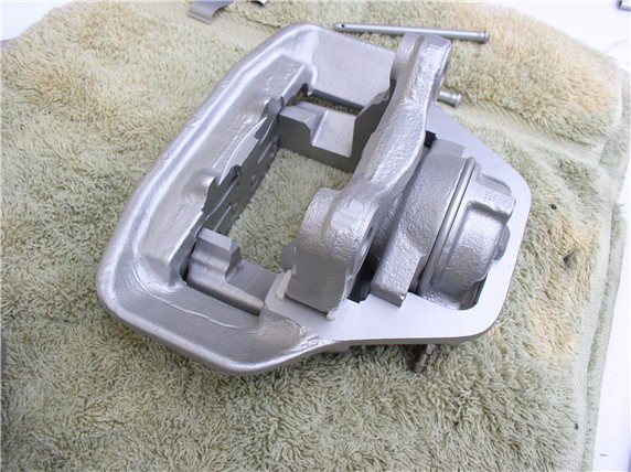
Here's both calipers out and ready for disassembly.
continued....
At this point, you can remove the caliper from the rotor. However, the brake pad sensor should still be attached.
To remove the brake pad sensor, you need to remove the sensor wire holder. Use a pair of pliers to remove the 2 retaining pins and the holder will slide off the retaining pins. Then, gently pull the wear sensor from the brake pad.
Now the caliper with pads should be free.
Set the caliper on a work surface and plug the brake line hole. I used a shop paper towel.
Next, you can take off the rotor. Use a large phillips screwdriver (or impact driver) to take the 2 screws out.
The rotor will come off after the 2 screws are out.
At this point, I discovered what was causing the scraping. A small pebble had jammed between the rotor shield and rotor.
Now you can measure the thickness of the rotor with a micrometer. Mine turned out to be about 19.7mm. New disk thickness is 20mm. Very little wear on my old ones. Wear limit is 18.6mm.
Place a baggie over the exposed brake line to prevent dirt from getting on the connection or inside the line.
Here's both calipers out and ready for disassembly.
continued....

 05-26-2008, 11:13 AM
#4
Addict
Rennlist Member
Rennlist Member
Dwayne thank you again for a detailed write up. Some day I will be referencing a few of these as I take on these tasks.
05-26-2008, 11:27 AM
#5
Three Wheelin'
Thread Starter
Join Date: Sep 2007
Location: Ridgecrest, California
Posts: 1,363
Likes: 0
Received 146 Likes
on
30 Posts
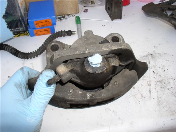
Next, remove the pins that retain the pads in the caliper. I used a punch and small hammer to lightly tap the end of the pin....
....then use a pair of pliers to grip the head of the pin and pull all the way out.
After both pins are out and the retaining spring clip are out, the pads will come out. Mine had disk brake quiet adhesive on them so it took some light prying to get the pads out.
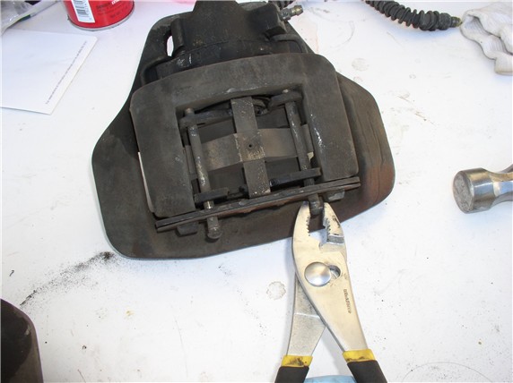
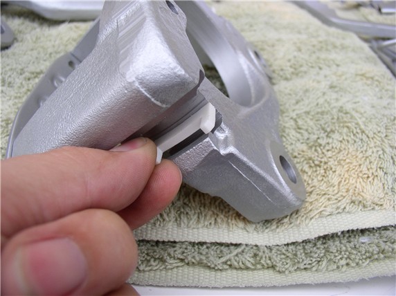
Next, separate the mounting frame (the piece that had the pins in it) from the floating frame (the large flat piece) by pushing down on the mounting frame. The guide spring is under tension so the frame will give some resistance. Don't remove it completely.....
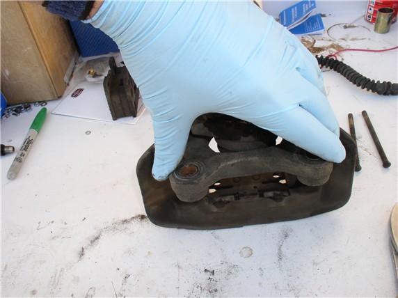
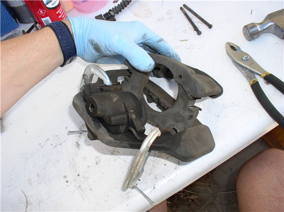
....I used a pair of small "C" clamps to hold the guide spring down and his allowed me to safely and easily remove the mounting frame.
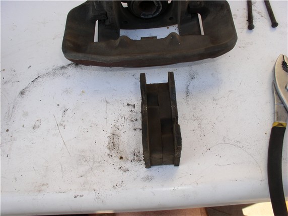
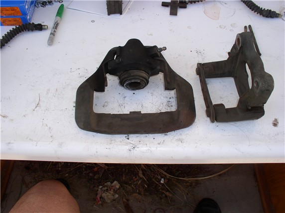
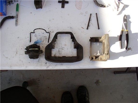
Here's the mounting frame (right) and the floating frame (left) separated.
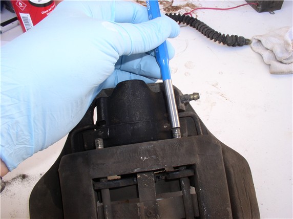
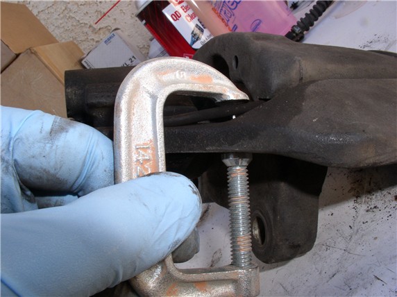
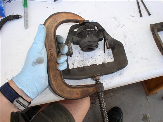
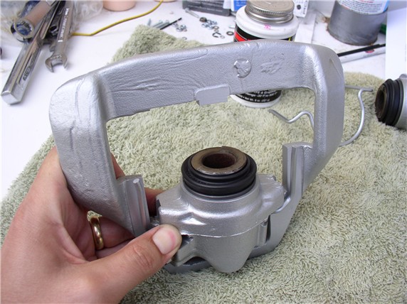
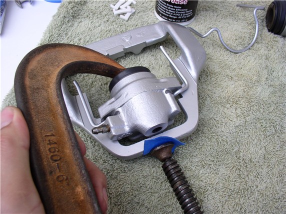
Now you can separate the cylinder from the floating frame. I used a large "C" clamp (6") to press out the cylinder. I prefer this method to the one cited in the WSM (i.e., hitting the cylinder with a plastic hammer).
All the parts have been disassembled from the frames.....
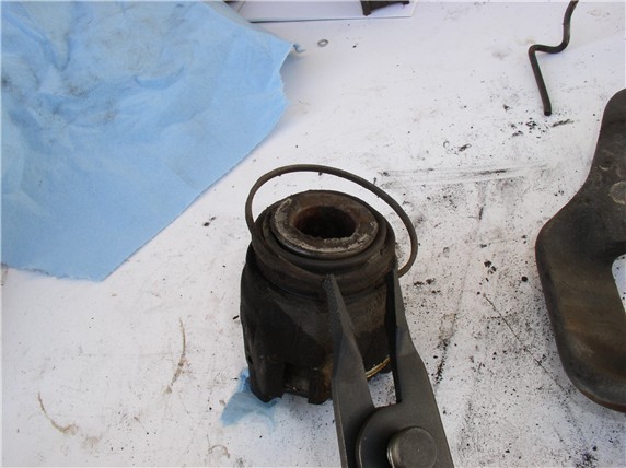
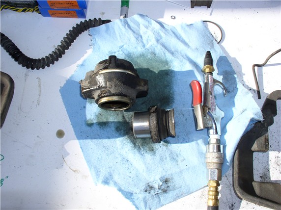
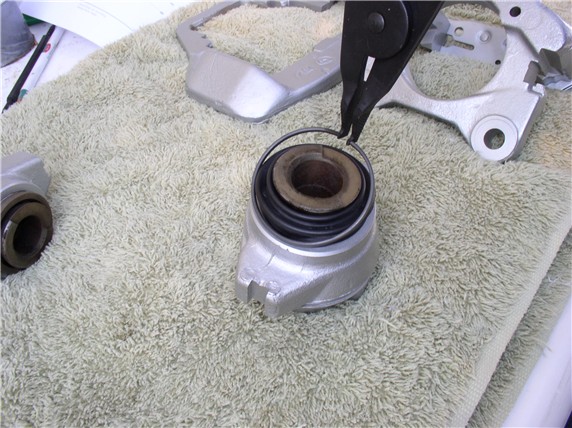
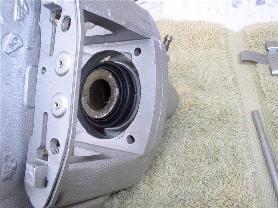
Next, you can focus on the cylinder disassembly. First, remove the clip that holds the dust boot in place. The clip pliers I used here have been great. Made by Powerbuilt, sold a Kragen.
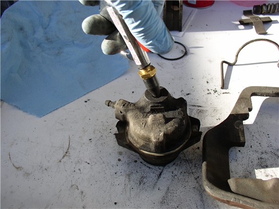
To remove the piston from the cylinder, I use a compressor. Before removing the piston, make note of its orientation. According to the WSM, it should be rotated about 20 degrees chamfer. Note the raised lip on the contact surface that meets with the brake pad. I noticed one edge of the raised lip lined up well with the bleeder fitting. Place the cylinder upside down (piston facing on the ground) and use an inflator adaptor to fill the cylinder with compressed air. It took between 40 and 60 PSI to press the piston out.
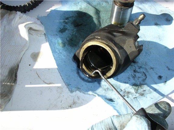
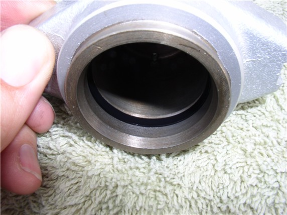
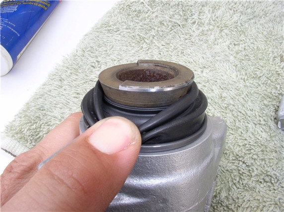
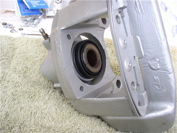
Once the piston is out, you can remove the dust boot and piston seal inside the cylinder.
To remove the seal, I used a small pick to carefully get under the seal without damaging the inside walls of the cylinder.....
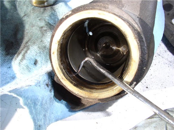
....then pull out the seal.
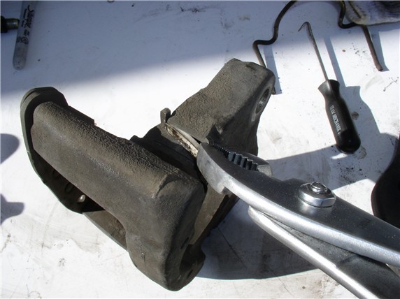
Next, you can remove the frame slides (little plastic slides) attached to the mounting frame. I used pliers to grip and rotate out. The caliper rebuild kit comes with new ones.
Continued......
....then use a pair of pliers to grip the head of the pin and pull all the way out.
After both pins are out and the retaining spring clip are out, the pads will come out. Mine had disk brake quiet adhesive on them so it took some light prying to get the pads out.
Next, separate the mounting frame (the piece that had the pins in it) from the floating frame (the large flat piece) by pushing down on the mounting frame. The guide spring is under tension so the frame will give some resistance. Don't remove it completely.....
....I used a pair of small "C" clamps to hold the guide spring down and his allowed me to safely and easily remove the mounting frame.
Here's the mounting frame (right) and the floating frame (left) separated.
Now you can separate the cylinder from the floating frame. I used a large "C" clamp (6") to press out the cylinder. I prefer this method to the one cited in the WSM (i.e., hitting the cylinder with a plastic hammer).
All the parts have been disassembled from the frames.....
Next, you can focus on the cylinder disassembly. First, remove the clip that holds the dust boot in place. The clip pliers I used here have been great. Made by Powerbuilt, sold a Kragen.
To remove the piston from the cylinder, I use a compressor. Before removing the piston, make note of its orientation. According to the WSM, it should be rotated about 20 degrees chamfer. Note the raised lip on the contact surface that meets with the brake pad. I noticed one edge of the raised lip lined up well with the bleeder fitting. Place the cylinder upside down (piston facing on the ground) and use an inflator adaptor to fill the cylinder with compressed air. It took between 40 and 60 PSI to press the piston out.
Once the piston is out, you can remove the dust boot and piston seal inside the cylinder.
To remove the seal, I used a small pick to carefully get under the seal without damaging the inside walls of the cylinder.....
....then pull out the seal.
Next, you can remove the frame slides (little plastic slides) attached to the mounting frame. I used pliers to grip and rotate out. The caliper rebuild kit comes with new ones.
Continued......
Last edited by Dwayne; 05-26-2008 at 12:23 PM.
05-26-2008, 11:33 AM
#6
Under the Lift
Lifetime Rennlist
Member
Lifetime Rennlist
Member
05-26-2008, 11:58 AM
#7
Three Wheelin'
Thread Starter
Join Date: Sep 2007
Location: Ridgecrest, California
Posts: 1,363
Likes: 0
Received 146 Likes
on
30 Posts
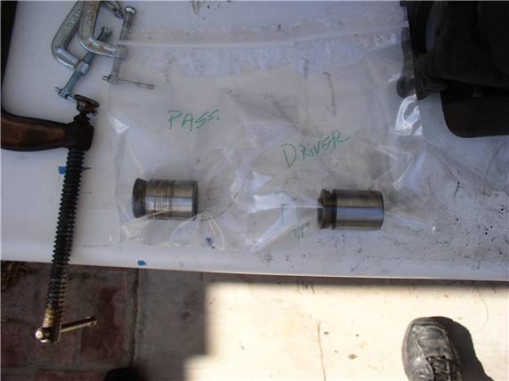
I wiped down the pistons and placed them in plastic baggies and labeled which cyliner each went with. I also marked the outside of the cylinder with a scribe to match the piston label.
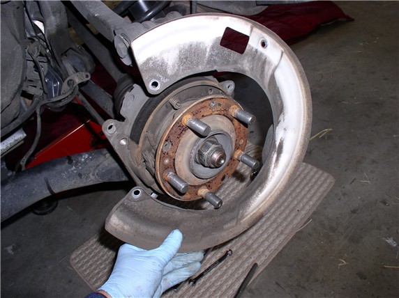
Back at the car, you can remove the rotor shield. It takes a 6mm allen bolt (3 of these) with a 13mm nut on the back side to counter hold. At the top of the shield there is a single 10mm bolt to take out as well.
Once the bolts are out, the shield comes off.
I use brake cleaner to clean the dust and dirt off the emergency brake shoes, springs, and adjustment wheel.
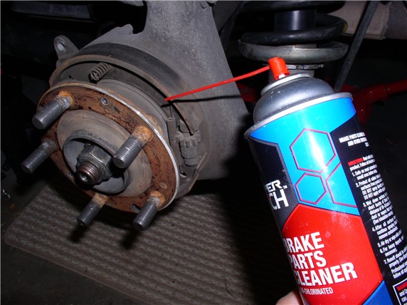
After the cleaning, inspect the shoes for wear or any other anomaly such as broken springs.
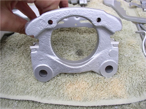
Now the cleaning begins! Usually, I take the caliper parts to the machine shop and have them clean/bead blast them. However, this time, I decided to give the parts an acid bath. The acid bath works great and only takes about 5-10 minutes. Once the parts are finished with the bath, I towel dry them immediately afterward.
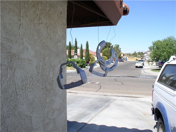
I used high temperature caliper paint and high temperature clear coat (available at Kragen). I fashioned hangers from clothes hangers to do the painting and hang for drying. I used a silver/aluminum color and applied 3 coats of paint and 2 coats of clear coat. Here's the rotor shields and frames drying....
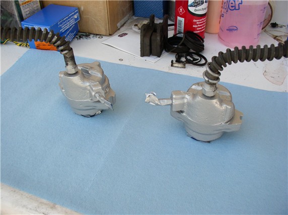
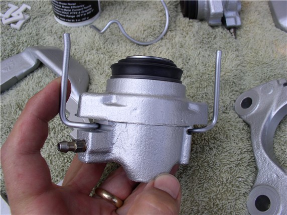
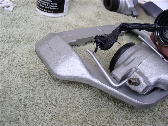
To paint the cylinders, I put the old brake hose back in the hole (since I had new brake lines). If you are not replacing the brake lines, you can stuff the brake line hose with a paper shop towel. Also, tape off the cylinder opening and the bleeder fitting. Here's the cylinder drying....
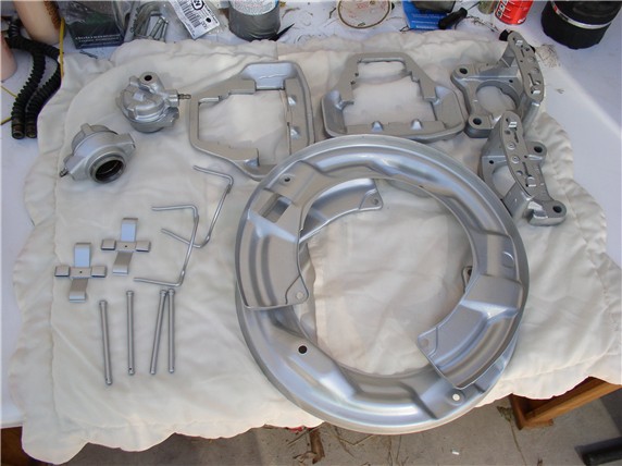
I also painted the pins, slides and pad retaining clip. Here's all the parts painted, dried and ready for reassembly.
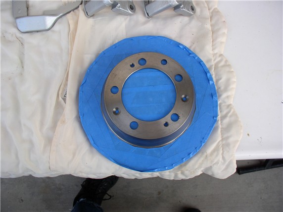
Next, I painted the rotor hats. First, use small pieces of painters tape to get a near perfect circle around the base of the hat.....
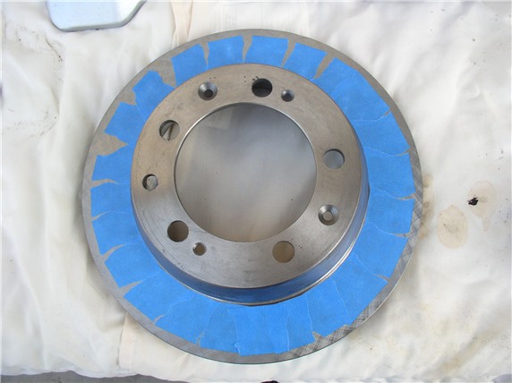
....then apply painter's tape to the remaining parts of the rotor (including the inside of the hat. Later you will use brake cleaner to remove any residue from the disk surface.
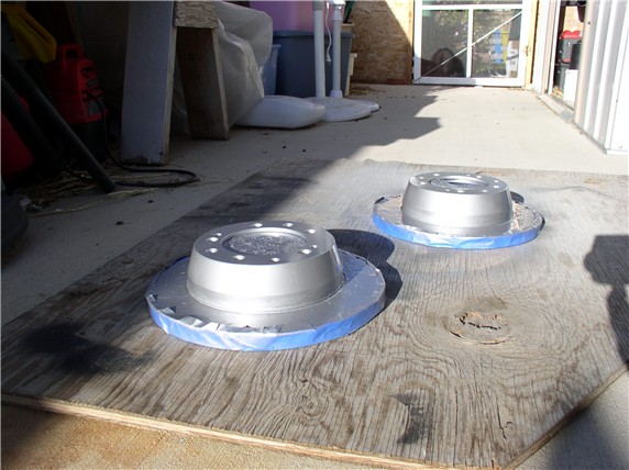
You can simply place the rotors on a flat surface for painting. I used an old piece of plywood.
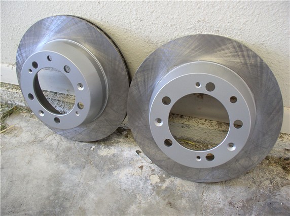
Once the paint and clear coat have dried, remove the tape.
Next, you're ready to install the caliper rebuild kit. Here's the kit and all the contents that come with it. It includes the dust boot, boot retaining clip, frame slides, cylinder/piston seal. You should be able to get the kits from any of the big 3. I used 928 Intl - fast, next day shipping at no extra cost - only 3 hours away!
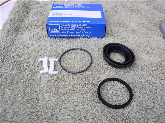
Continued.....
Back at the car, you can remove the rotor shield. It takes a 6mm allen bolt (3 of these) with a 13mm nut on the back side to counter hold. At the top of the shield there is a single 10mm bolt to take out as well.
Once the bolts are out, the shield comes off.
I use brake cleaner to clean the dust and dirt off the emergency brake shoes, springs, and adjustment wheel.
After the cleaning, inspect the shoes for wear or any other anomaly such as broken springs.
Now the cleaning begins! Usually, I take the caliper parts to the machine shop and have them clean/bead blast them. However, this time, I decided to give the parts an acid bath. The acid bath works great and only takes about 5-10 minutes. Once the parts are finished with the bath, I towel dry them immediately afterward.
I used high temperature caliper paint and high temperature clear coat (available at Kragen). I fashioned hangers from clothes hangers to do the painting and hang for drying. I used a silver/aluminum color and applied 3 coats of paint and 2 coats of clear coat. Here's the rotor shields and frames drying....
To paint the cylinders, I put the old brake hose back in the hole (since I had new brake lines). If you are not replacing the brake lines, you can stuff the brake line hose with a paper shop towel. Also, tape off the cylinder opening and the bleeder fitting. Here's the cylinder drying....
I also painted the pins, slides and pad retaining clip. Here's all the parts painted, dried and ready for reassembly.
Next, I painted the rotor hats. First, use small pieces of painters tape to get a near perfect circle around the base of the hat.....
....then apply painter's tape to the remaining parts of the rotor (including the inside of the hat. Later you will use brake cleaner to remove any residue from the disk surface.
You can simply place the rotors on a flat surface for painting. I used an old piece of plywood.
Once the paint and clear coat have dried, remove the tape.
Next, you're ready to install the caliper rebuild kit. Here's the kit and all the contents that come with it. It includes the dust boot, boot retaining clip, frame slides, cylinder/piston seal. You should be able to get the kits from any of the big 3. I used 928 Intl - fast, next day shipping at no extra cost - only 3 hours away!
Continued.....
Trending Topics
05-26-2008, 12:19 PM
#8
Three Wheelin'
Thread Starter
Join Date: Sep 2007
Location: Ridgecrest, California
Posts: 1,363
Likes: 0
Received 146 Likes
on
30 Posts
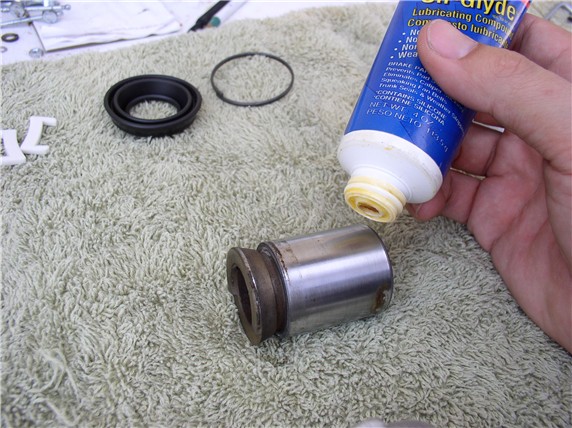
To begin the cylinder assembly, the WSM suggests using brake cylinder paste on the cylinder walls, the piston and the seal (a very thin coat). I used silicone lubricant and applied a VERY THIN coat.
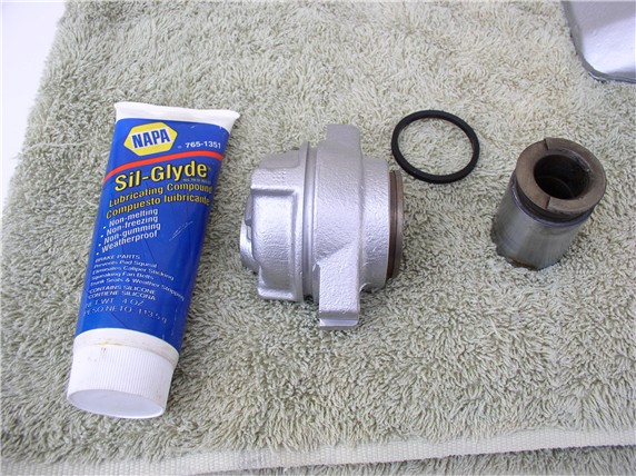
First, apply the lubricant to the cylinder walls....
....then apply to the seal....
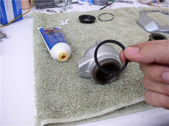
....and place the seal back into the groove in the cylinder.
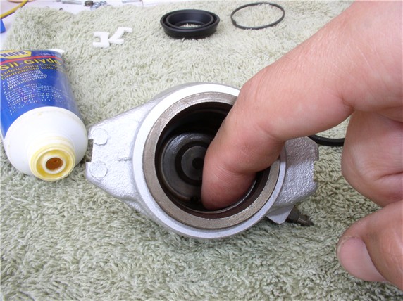
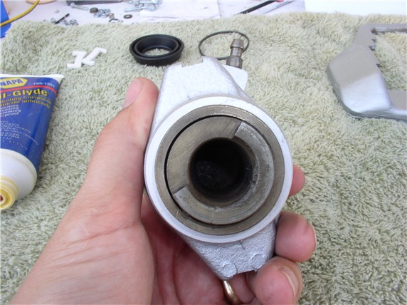
Then put a very thin coat of lubricant on the piston outer surface.
Then position the piston according to the same orientation it came out. According to the WSM, about a 20 degree chamfer.
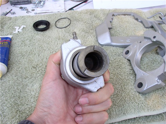
You should be able to press the piston in using both hands. But don't press it in all the way. You still need to attach the dust boot. Leave enough room that you can comfortably access the piston groove for the dust boot.
Next, according to the instructions in the caliper rebuild kit, apply a very thin coat of lubricant to the inside of the dust boot.
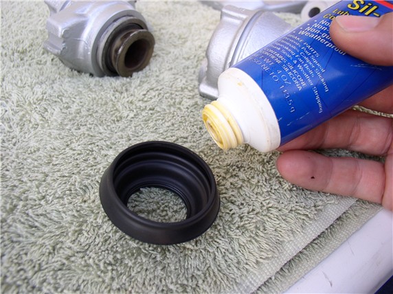
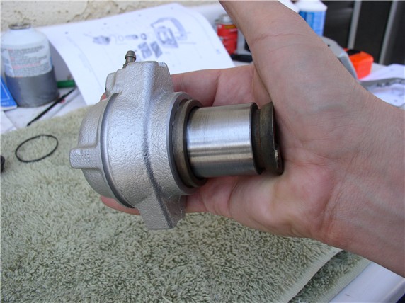
Then place the dust boot (small opening) on the piston first....
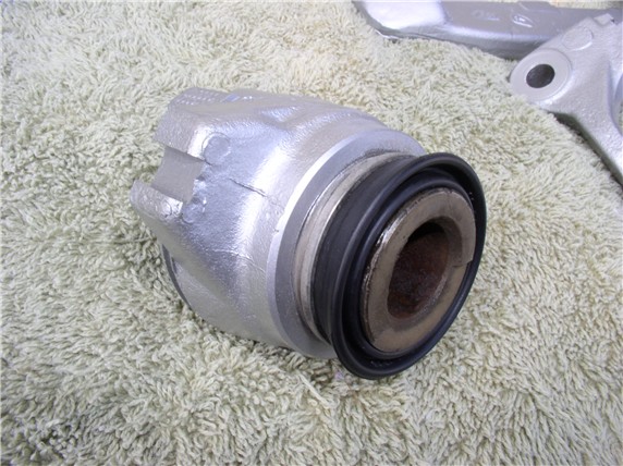
....and pull the other end of the dust boot over the cylinder and on top of the dust boot groove.
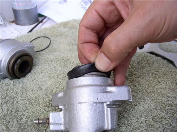
Next, install the dust boot retaining clip.
Make sure the clip is seated properly and up next to the cylinder edge.
Finally, check to make sure the dust boot is properly seated on the piston as well.
Continued.....
First, apply the lubricant to the cylinder walls....
....then apply to the seal....
....and place the seal back into the groove in the cylinder.
Then put a very thin coat of lubricant on the piston outer surface.
Then position the piston according to the same orientation it came out. According to the WSM, about a 20 degree chamfer.
You should be able to press the piston in using both hands. But don't press it in all the way. You still need to attach the dust boot. Leave enough room that you can comfortably access the piston groove for the dust boot.
Next, according to the instructions in the caliper rebuild kit, apply a very thin coat of lubricant to the inside of the dust boot.
Then place the dust boot (small opening) on the piston first....
....and pull the other end of the dust boot over the cylinder and on top of the dust boot groove.
Next, install the dust boot retaining clip.
Make sure the clip is seated properly and up next to the cylinder edge.
Finally, check to make sure the dust boot is properly seated on the piston as well.
Continued.....
05-26-2008, 12:49 PM
#9
Three Wheelin'
Thread Starter
Join Date: Sep 2007
Location: Ridgecrest, California
Posts: 1,363
Likes: 0
Received 146 Likes
on
30 Posts
Next, you can assemble the cylinder onto the floating frame. First, place the guide spring in the spring groove on the cylinder.
Now, position the cylinder on the floating frame by lining up the slots on the cylinder with the notched frame edges.
Use the large "C" clamp to press the cylinder on the frame until you encounter stiff resistance. Doing this will press the pistion all the way into the cylinder. After the cylinder was seated in the floating frame, I then use the compressed air to push out the piston slightly, just enough so that the contact lip on the piston was protruding out from the dust boot. I did not want the dust boot to make contact with the tacky surface of the back of the brake pads.
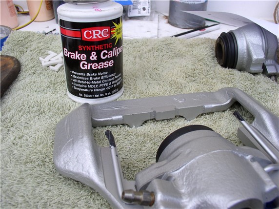
Lubricate the end of the guide spring with brake caliper grease.
Install the plastic slides into the mounting frame.
Next, position the mounting frame inside the floating frame and position the ends of the guide spring into their respective slots on the mounting frame. To do this, you will need to spread the guide spring out in order to line up with the slots.
After the guide spring is lined up with the mounting frame slots, you will need to push down on the mounting frame while at the same time pushing in toward the cylinder in order to line up the plastic guides with the notched edge of the floating frame. Unfortunately, I did not have three hands to demonstrate....I suppose I could have used the small "C" clamps again to hold down the guide spring - but that didn't occur to me until just now!
When it's in place, it should look like this...
Next comes the brake pads. I use Disk Brake Quiet on the backs of the pads. It's a tacky spray that eliminates pad squeak.
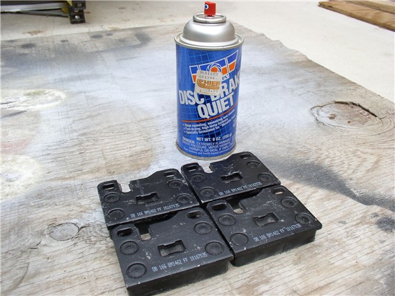
Just use one coat. Not too light of a coat and not too heavy either.
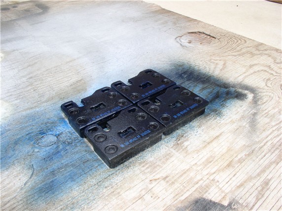
Continued.....
Now, position the cylinder on the floating frame by lining up the slots on the cylinder with the notched frame edges.
Use the large "C" clamp to press the cylinder on the frame until you encounter stiff resistance. Doing this will press the pistion all the way into the cylinder. After the cylinder was seated in the floating frame, I then use the compressed air to push out the piston slightly, just enough so that the contact lip on the piston was protruding out from the dust boot. I did not want the dust boot to make contact with the tacky surface of the back of the brake pads.
Lubricate the end of the guide spring with brake caliper grease.
Install the plastic slides into the mounting frame.
Next, position the mounting frame inside the floating frame and position the ends of the guide spring into their respective slots on the mounting frame. To do this, you will need to spread the guide spring out in order to line up with the slots.
After the guide spring is lined up with the mounting frame slots, you will need to push down on the mounting frame while at the same time pushing in toward the cylinder in order to line up the plastic guides with the notched edge of the floating frame. Unfortunately, I did not have three hands to demonstrate....I suppose I could have used the small "C" clamps again to hold down the guide spring - but that didn't occur to me until just now!
When it's in place, it should look like this...
Next comes the brake pads. I use Disk Brake Quiet on the backs of the pads. It's a tacky spray that eliminates pad squeak.
Just use one coat. Not too light of a coat and not too heavy either.
Continued.....
05-26-2008, 01:08 PM
#10
Three Wheelin'
Thread Starter
Join Date: Sep 2007
Location: Ridgecrest, California
Posts: 1,363
Likes: 0
Received 146 Likes
on
30 Posts
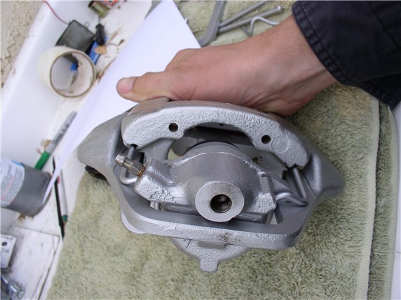
At this point, it's a good idea to double check the orientation of the piston. This is the last opportunity to make any adjustments if they are not at the proper rotation.
According to the WSM, you can use piston pliers (don't know what those look like) to rotate the piston, if needed. Mine looked OK.
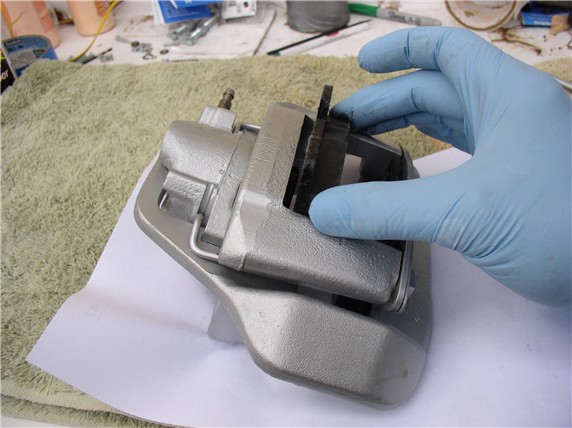
Next, install the brake pads, I installed the outer pad first. It has a slot in the back of the pad that lines up with and presses into a rectangular notch on the floating frame. Be very careful to not touch the pad surface if you have also touched the tacky brake quiet material. If you need to press the pads in place, use a shop towel between the pad surface and your fingers/gloves.
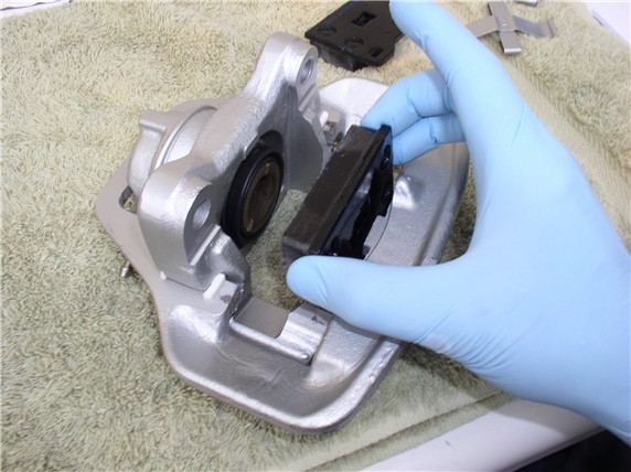
Place the inner pad (against the piston) next.
Now you can insert the retaining pins and clip. Start with one of the pins and line it up with the holes in the mounting frame and the brake pads - push it all the way through.
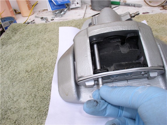
Next, install the spring retaining clip and second pin. Slide the wide end under the first installed pin. You will need to press down on the other end of the spring clip in order to get it under the second pin. Slide the second pin in while holding down the spring clip.
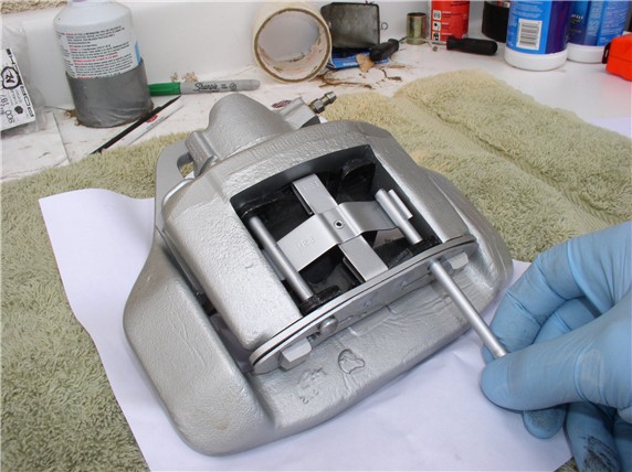
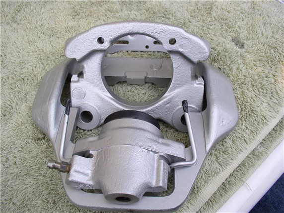
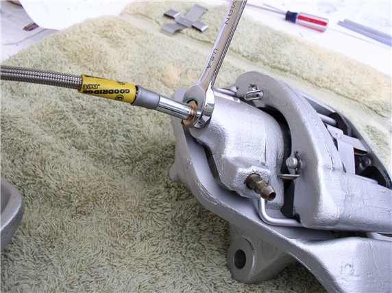
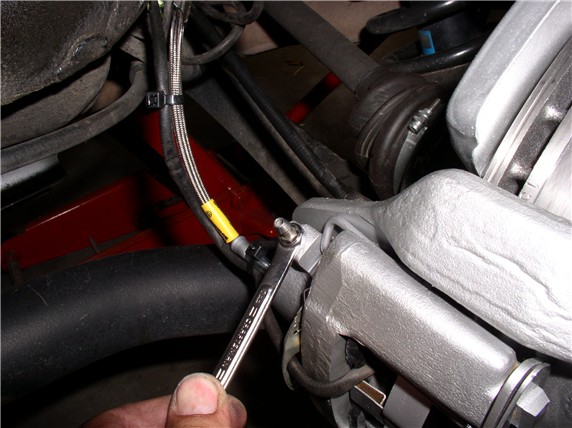
Now install the new brake line. I'm using the stainless steel braided hose.
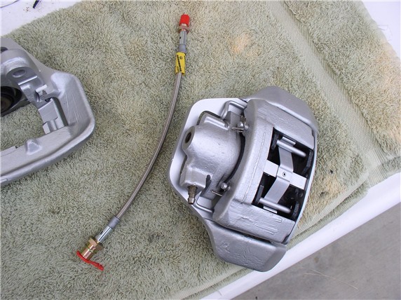
Connect the male end of the hose to the cylinder using the 13mm wrench and tighten to 10 ftlb.
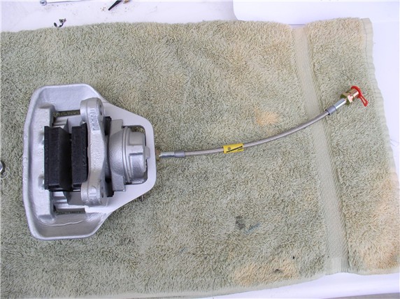
At this point, the caliper is ready to go back on to the car. Keep the plastic cap on the other end of the line until ready to connect to the brake line.
Continued.....
According to the WSM, you can use piston pliers (don't know what those look like) to rotate the piston, if needed. Mine looked OK.
Next, install the brake pads, I installed the outer pad first. It has a slot in the back of the pad that lines up with and presses into a rectangular notch on the floating frame. Be very careful to not touch the pad surface if you have also touched the tacky brake quiet material. If you need to press the pads in place, use a shop towel between the pad surface and your fingers/gloves.
Place the inner pad (against the piston) next.
Now you can insert the retaining pins and clip. Start with one of the pins and line it up with the holes in the mounting frame and the brake pads - push it all the way through.
Next, install the spring retaining clip and second pin. Slide the wide end under the first installed pin. You will need to press down on the other end of the spring clip in order to get it under the second pin. Slide the second pin in while holding down the spring clip.
Now install the new brake line. I'm using the stainless steel braided hose.
Connect the male end of the hose to the cylinder using the 13mm wrench and tighten to 10 ftlb.
At this point, the caliper is ready to go back on to the car. Keep the plastic cap on the other end of the line until ready to connect to the brake line.
Continued.....
05-26-2008, 01:21 PM
#11
The Lady's Man
Rennlist Member
Rennlist Member
Join Date: Sep 2003
Location: south O.C. california
Posts: 10,444
Likes: 0
Received 0 Likes
on
0 Posts
One of the best writeups I have seen both in detail and photos. The photos are really great and clear which makes the instructions easier to follow. Thanks!!
 05-26-2008, 01:38 PM
#13
Three Wheelin'
Thread Starter
Join Date: Sep 2007
Location: Ridgecrest, California
Posts: 1,363
Likes: 0
Received 146 Likes
on
30 Posts
Next, install the rotor shield. These are fitted left and right so you can't mix them up.
Use the 6mm allen and 13mm wrench to counter hold the 3 allen bolts. Also, re-install and tighten the 10mm bolt at the top of the shield. I decided to be adventurous and paint the heads of the bolts glossy black.
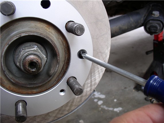
Install the rotors next. line up the phillips screw holes and press onto the wheel hub....
....and tighten the 2 phillips head screws. Also painted them black.
Before installing the caliper, clean the surface of the rotors with brake cleaner and a shop towel. I belive a cloth towel works better than the paper sort. Spray the cleaner directly on the towel and wipe the surface (both sides) with the towel.
Next, install the caliper by tilting it into place and line up the holes for the caliper bolts at hub carrier.
Next, install the caliper bolts using the 19mm (or 3/4") socket and combo wrenches.
Install the brake pad wear sensor holding bracket. Feed the end of the sensor through the holder and place the bracket on the mounting pins at the back of the caliper - the same pins that hold the brake pads in place.
Connect the brake pad wear sensor to the brake pad. Be careful when insterting the plastic fitting into the brake as these can be brittle and crack when forced. If it cracks and breaks, it will not stay in place.
Install the wear sensor holding bracket locking pins.
Remove the plastic baggie on the end of the brake line and position the caliper brake hose to match up with the steel brake line at the body bracket.
Connect the brake line with the female fitting on the caliper hose and hand tighten. Then, install the brake hose retaining clip on the hose fitting and body mounting bracket. This will give the connection extra resistance as you tighten the connection. Counterhold the brake hose with the 17mm wrench and tighten the brake line nut with the 11mm wrench to 10 ftlb.
Install cable zip ties around the brake wear sensor wire and the caliper brake hose. I used three zip ties on each wheel.
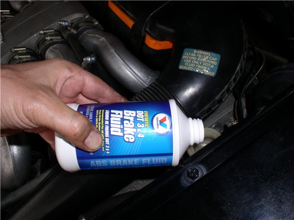
Add brake fluid to the reservior to make sure it's full before bleeding the lines. You will need to check the level of the reservior frequently as you are bleeding the lines. I accidently let it get too low and ended up sucking air into the lines.
Continued.....
Use the 6mm allen and 13mm wrench to counter hold the 3 allen bolts. Also, re-install and tighten the 10mm bolt at the top of the shield. I decided to be adventurous and paint the heads of the bolts glossy black.
Install the rotors next. line up the phillips screw holes and press onto the wheel hub....
....and tighten the 2 phillips head screws. Also painted them black.
Before installing the caliper, clean the surface of the rotors with brake cleaner and a shop towel. I belive a cloth towel works better than the paper sort. Spray the cleaner directly on the towel and wipe the surface (both sides) with the towel.
Next, install the caliper by tilting it into place and line up the holes for the caliper bolts at hub carrier.
Next, install the caliper bolts using the 19mm (or 3/4") socket and combo wrenches.
Install the brake pad wear sensor holding bracket. Feed the end of the sensor through the holder and place the bracket on the mounting pins at the back of the caliper - the same pins that hold the brake pads in place.
Connect the brake pad wear sensor to the brake pad. Be careful when insterting the plastic fitting into the brake as these can be brittle and crack when forced. If it cracks and breaks, it will not stay in place.
Install the wear sensor holding bracket locking pins.
Remove the plastic baggie on the end of the brake line and position the caliper brake hose to match up with the steel brake line at the body bracket.
Connect the brake line with the female fitting on the caliper hose and hand tighten. Then, install the brake hose retaining clip on the hose fitting and body mounting bracket. This will give the connection extra resistance as you tighten the connection. Counterhold the brake hose with the 17mm wrench and tighten the brake line nut with the 11mm wrench to 10 ftlb.
Install cable zip ties around the brake wear sensor wire and the caliper brake hose. I used three zip ties on each wheel.
Add brake fluid to the reservior to make sure it's full before bleeding the lines. You will need to check the level of the reservior frequently as you are bleeding the lines. I accidently let it get too low and ended up sucking air into the lines.
Continued.....
05-26-2008, 02:04 PM
#14
Three Wheelin'
Thread Starter
Join Date: Sep 2007
Location: Ridgecrest, California
Posts: 1,363
Likes: 0
Received 146 Likes
on
30 Posts
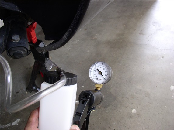
Next, loosen the bleeder fitting. If the bleeder is not clogged, you should see some fluid slowly dripping out.
I used the vacuum pump approach to get the air out of the lines. This is the first time I've used this approach, so it took some practice. A couple of tricks I learned. First, air was being sucked through the threads of the bleeder fitting. So I removed the fitting and put on some teflon tape. That fixed the problem. Second, be careful how much fluid you suck out, I accidently drained the reservior and saw lots of air bubbles coming through! When tightening the bleeder fittings, they only need to be tightened about 3 ftlb.
I did run into a plugged bleeder fitting and wondered how it got plugged. Then I noticed that each of the fittings is supposed to have a protective cap on it to prevent dirt from entering. All my caps are gone so I need to get some new ones. In the meantime, if you have a clogged fitting, take it out and use a small pick to clean the orifice. Make sure you can blow air through it before putting it back in. Put the teflon tape on the threads to ensure a good air tight fit for the vacuum pump.
Once the system is bled, top off the brake fluid reservior and check the rotation of the axle/brakes for any anomalies. The wheels should rotate smoothly but firmly. Check the operation of the emergency brake. Mine required no adjustment. I believe I read in the WSM that the emergency brake should engage after about 2 clicks on the e-brake handle. If yours is more than that, you may need to adjust the adjusting wheel at the emergency brake shoes according the procedure in the WSM.
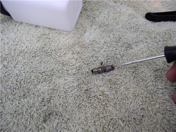
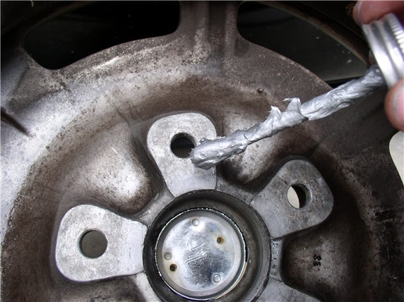
Finally, mount the wheels to the car. I used optimoly TA, the aluminum anti-sieze, on the mating surface of the wheel.
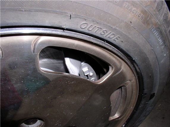
Then mount the wheel, lower the car and take it for a test drive and listen for unusual noises. Also, no hard braking for the first 50-100 miles so the brakes can bed in against the disks.
That's it!
I've tested mine and they seem to be doing just fine. Mark another job off the list! Please feel free to comment or recommend any improvements to this process as I'm learning along the way. THANKS for reading!
I used the vacuum pump approach to get the air out of the lines. This is the first time I've used this approach, so it took some practice. A couple of tricks I learned. First, air was being sucked through the threads of the bleeder fitting. So I removed the fitting and put on some teflon tape. That fixed the problem. Second, be careful how much fluid you suck out, I accidently drained the reservior and saw lots of air bubbles coming through! When tightening the bleeder fittings, they only need to be tightened about 3 ftlb.
I did run into a plugged bleeder fitting and wondered how it got plugged. Then I noticed that each of the fittings is supposed to have a protective cap on it to prevent dirt from entering. All my caps are gone so I need to get some new ones. In the meantime, if you have a clogged fitting, take it out and use a small pick to clean the orifice. Make sure you can blow air through it before putting it back in. Put the teflon tape on the threads to ensure a good air tight fit for the vacuum pump.
Once the system is bled, top off the brake fluid reservior and check the rotation of the axle/brakes for any anomalies. The wheels should rotate smoothly but firmly. Check the operation of the emergency brake. Mine required no adjustment. I believe I read in the WSM that the emergency brake should engage after about 2 clicks on the e-brake handle. If yours is more than that, you may need to adjust the adjusting wheel at the emergency brake shoes according the procedure in the WSM.
Finally, mount the wheels to the car. I used optimoly TA, the aluminum anti-sieze, on the mating surface of the wheel.
Then mount the wheel, lower the car and take it for a test drive and listen for unusual noises. Also, no hard braking for the first 50-100 miles so the brakes can bed in against the disks.
That's it!
I've tested mine and they seem to be doing just fine. Mark another job off the list! Please feel free to comment or recommend any improvements to this process as I'm learning along the way. THANKS for reading!
05-26-2008, 02:14 PM
#15
Addict
Rennlist Member
Rennlist Member

Join Date: May 2003
Posts: 1,118
Likes: 0
Received 0 Likes
on
0 Posts
Dwayne,
This is definitely going into my list of references. And lucky me, I also have an '84. So, your great write-up and pics will come in very handy when the need arises!
This is definitely going into my list of references. And lucky me, I also have an '84. So, your great write-up and pics will come in very handy when the need arises!
Last edited by ACG; 05-26-2008 at 08:49 PM.