When you click on links to various merchants on this site and make a purchase, this can result in this site earning a commission. Affiliate programs and affiliations include, but are not limited to, the eBay Partner Network.
Here's what I've found out about surface finish, over the years. Some heads (notice "some") are very sensitive to intake surface finish. This can be a real pain in the butt, when one is "working" up a port design on the flow bench. I've had situations where heads will have significant flow gains, when rough ported and then loose all those gains (and sometimes more than what was gained, when the roughness is removed and retested.) Air flow is laminar through the port. This means that the air that is moving along the walls of the port is moving completely different than the air through the rest of the port. I think that what I've learned is that the air that flows along the walls is essentially rolling along in little circles. The smoother the finish, the bigger the circles are, in most ports. There needs to be texture there to "break" the air circles up and make them smaller. I clean up the intake ports with 60 grit sanding cones...sometimes 80, but certainly no finer. The best consistant surface i've found is a very smooth 60 to 80 grit surface that is then bead blasted with "D" beads at about 80 psi. This tends to re-expose the little holes in the casting, which really improves the flow.
This is generally why ported heads work better after they have been run and get the next valve grind. The shops generally bead blast the ports....removing the polished surface...and airflow increases can be as high as 20%! It seems crazy, but it works. You can never go wrong with this surface finish on the entire intake track, including the intake manifold.
Just reading this very interesting thread for the first time.
Greg I believe your observations to be very correct, but a little terminology clarification on what I believe you are seeing. My day job is as an aerodynamicist, so fluid flow is a subject I am familiar with. Laminar flow by definition is smooth and without vorticies (little circles). It is difficult for air to remain laminar on a surface for very long before transitioning to a turbulent boundary layer. Aerodynamicists have spent decades and millions of dollars trying to develop natural laminar flow wings in an effort to reduce drag without complete success. And to get there takes very expensive treatments to the wings with very specialized (i.e. expensive to build) airfoil designs. So instead of trying to win that battle, aero engineers try to delay the transition from laminar flow to turbulent flow and work even harder to prevent separation of the boundary layer all together. And that is what I believe is going on here. What you are actually observing is the difference between a turbulent boundary layer (little circles) and separated boundary layer (bigger circles).
The rough ported surface trips the flow and creates turbulence which adds energy back into the boundary layer helping it to stay attached and preventing separation. When you polish the surface smooth the flow is more apt to separate causing a sudden and large loss in flow velocity (dynamic head pressure) and therefore a loss in performance. This is what you are seeing with the polished performance losses. The downside to the rough surface in an increase in skin friction and therefore an associated loss in flow velocity however not near the loss associated with separated flow.
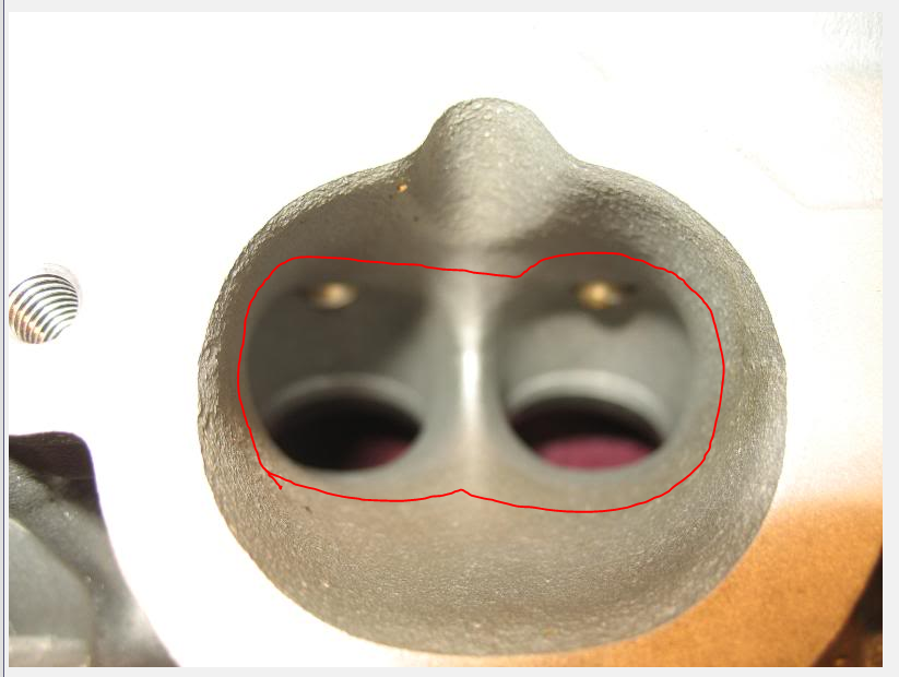
One way to possibly mitigate these losses in this application and get the best of both worlds (i.e. laminar and turbulent) would be to polish the port only in the areas were the surface is flat without much curvature and then leave the surface rough just before any large turns or small radii start. In the case of the intake port you would only polish the surfaces outside the red line.
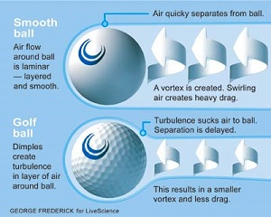
This same principal is used on the leading edges of some airplanes to delay flow separation at high angles of attack. Actually the best analogy to all of this is golf ball aerodynamics. The reason golf ***** have dimples and are not smooth is to delay boundary layer separation therefore reducing drag. It seems counter intuitive but once you study the flow fields it makes perfect sense.
Just reading this very interesting thread for the first time.
Greg I believe your observations to be very correct, but a little terminology clarification on what I believe you are seeing. My day job is as an aerodynamicist, so fluid flow is a subject I am familiar with. Laminar flow by definition is smooth and without vorticies (little circles). It is difficult for air to remain laminar on a surface for very long before transitioning to a turbulent boundary layer. Aerodynamicists have spent decades and millions of dollars trying to develop natural laminar flow wings in an effort to reduce drag without complete success. And to get there takes very expensive treatments to the wings with very specialized (i.e. expensive to build) airfoil designs. So instead of trying to win that battle, aero engineers try to delay the transition from laminar flow to turbulent flow and work even harder to prevent separation of the boundary layer all together. And that is what I believe is going on here. What you are actually observing is the difference between a turbulent boundary layer (little circles) and separated boundary layer (bigger circles).
The rough ported surface trips the flow and creates turbulence which adds energy back into the boundary layer helping it to stay attached and preventing separation. When you polish the surface smooth the flow is more apt to separate causing a sudden and large loss in flow velocity (dynamic head pressure) and therefore a loss in performance. This is what you are seeing with the polished performance losses. The downside to the rough surface in an increase in skin friction and therefore an associated loss in flow velocity however not near the loss associated with separated flow.
One way to possibly mitigate these losses in this application and get the best of both worlds (i.e. laminar and turbulent) would be to polish the port only in the areas were the surface is flat without much curvature and then leave the surface rough just before any large turns or small radii start. In the case of the intake port you would only polish the surfaces outside the red line.
This same principal is used on the leading edges of some airplanes to delay flow separation at high angles of attack. Actually the best analogy to all of this is golf ball aerodynamics. The reason golf ***** have dimples and are not smooth is to delay boundary layer separation therefore reducing drag. It seems counter intuitive but once you study the flow fields it makes perfect sense.
Some time ago, I computed the Reynolds number for some conditions in the port. I recall that my conclusion was that the only time when the flow might be laminar in these heads is at the valve seat when testing very-low-lift flow on flow bench with a low test pressure. That's from memory. Does that ring true to you?
The Formula 1 ports are not roughed up, they are smooth. I think (but don't know) that this is because they are so straight and shaped perfectly when they are not straight. The flow doesn't have to turn, and therefore the thicker boundary layer would just be friction. I think this is consistent with your explanation.
There's an additional consideration. I think that if the ports are way too large to start with, roughing up even the straight parts may help. I'm thinking that the thicker boundary layer might make the port look effectively smaller and force the flow in the center to be faster, generating stronger waves as piston decelerates. Since air is compressible, I wouldn't think this is an efficient way to generate waves, but it may be better than way oversized ports? This would show up as reduced CFM on the flow bench but increased power on the dyno, if the theory is correct.
Finally, there's always the distribution of fuel, and on a running engine that's important.
Does this make sense, given your training?
A quick comment on your drawing: I'd think that there's little risk of separation on the long-side radius as it sees the dynamic pressure from the angle. It's the short side where my intuition says that the separation risk is high. My intuition says to generate turbulence only right before the short-side turn on the port floor. My intuition is known to be unreliable, however.
Just reading this very interesting thread for the first time.
Greg I believe your observations to be very correct, but a little terminology clarification on what I believe you are seeing. My day job is as an aerodynamicist, so fluid flow is a subject I am familiar with. Laminar flow by definition is smooth and without vorticies (little circles). It is difficult for air to remain laminar on a surface for very long before transitioning to a turbulent boundary layer. Aerodynamicists have spent decades and millions of dollars trying to develop natural laminar flow wings in an effort to reduce drag without complete success. And to get there takes very expensive treatments to the wings with very specialized (i.e. expensive to build) airfoil designs. So instead of trying to win that battle, aero engineers try to delay the transition from laminar flow to turbulent flow and work even harder to prevent separation of the boundary layer all together. And that is what I believe is going on here. What you are actually observing is the difference between a turbulent boundary layer (little circles) and separated boundary layer (bigger circles).
The rough ported surface trips the flow and creates turbulence which adds energy back into the boundary layer helping it to stay attached and preventing separation. When you polish the surface smooth the flow is more apt to separate causing a sudden and large loss in flow velocity (dynamic head pressure) and therefore a loss in performance. This is what you are seeing with the polished performance losses. The downside to the rough surface in an increase in skin friction and therefore an associated loss in flow velocity however not near the loss associated with separated flow.
One way to possibly mitigate these losses in this application and get the best of both worlds (i.e. laminar and turbulent) would be to polish the port only in the areas were the surface is flat without much curvature and then leave the surface rough just before any large turns or small radii start. In the case of the intake port you would only polish the surfaces outside the red line.
This same principal is used on the leading edges of some airplanes to delay flow separation at high angles of attack. Actually the best analogy to all of this is golf ball aerodynamics. The reason golf ***** have dimples and are not smooth is to delay boundary layer separation therefore reducing drag. It seems counter intuitive but once you study the flow fields it makes perfect sense.
It is always terrific to get feedback from a professional. Thanks!
This is simple to do....I'll give it a try on my next set of heads.
don't know how many lambs you've driven, but the power delivery is baaad
i'll take my things and go.
The white 928 coming up at the right side in this video drives like a lamb according to the builder and former owner. I do not think the power is baaad. It is supposed to be one of the most powerful NA 928 ever built. The video camera is sitting in a 300 hp Honda race car.
�ke
There is no need to guess about surface finish where it pertains to performance gains. The turbo heads I just got back for my 930 feature rough intakes, smooth exhausts.
The heads on my 850whp Camaro are the same. Just saw the heads on the bench for a 2000HP LT4 running 20+pounds of boost. SAME.
Formula 1 does it's own thing. I think it's pretty much established that the intake tracts of heads need to be rough, terminology aside.
This is backwards in being applied to "rough" vs. "smooth." (It's also wrong for the golf ball but that's another issue.)
A rough surface creates turbulent flow along the surface. This reduces the drag applied from the walls to the rest of the airflow.
The same thing applies to a flying golf ball so its spinning doesn't create as much hook and less regular drag.
Whatever does "sucks air to ball" even supposed to mean? Nah... don't answer.
Turbulent flow has higher skin friction drag than laminar flow. This is due to the viscous shearing forces between the laminar layers in laminar flow being lower than those in turbulent flow. I had to open up my old text books for this pic, but you can see by looking at the Moody chart for pipe flow that laminar flow in a pipe can only be held up to Reynolds numbers of about 2000. That is really slow flow (Laminar flow can be maintained at higher Reynolds numbers for external flows since the boundary layers are allowed to grow without constraint). Beyond that there is transition to turbulent flow. For any given Reynolds number and pipe diameter if you increase the surface roughness (ε/d on the right axis) the friction factor (drag and subsequent pressure loss) increases.
The reduction of drag on a dimpled (i.e. rough) golf ball vs. a smooth golf ball is due to the reduction of the separated region behind the ball which creates a vacuum which is trying to "suck" the ball in the opposite direction it is traveling. The dimples act as a means to transition the the flow from laminar to turbulent which is desired because turbulent flow is more resistant to separation. You can't prevent separation around a sphere but the turbulent flow does reduce the area of the separated zone and that is what that golf ball graphic shows.
Here is nice flow visual of this effect on a bowling ball being dropped in water. The ball on the left is smooth and therefore exhibits laminar separation early on the surface. The ball on the right has a small patch of sand paper on its nose to trip the boundary layer. The result is better flow attachment and a smaller wake.
Some time ago, I computed the Reynolds number for some conditions in the port. I recall that my conclusion was that the only time when the flow might be laminar in these heads is at the valve seat when testing very-low-lift flow on flow bench with a low test pressure. That's from memory. Does that ring true to you?
The Formula 1 ports are not roughed up, they are smooth. I think (but don't know) that this is because they are so straight and shaped perfectly when they are not straight. The flow doesn't have to turn, and therefore the thicker boundary layer would just be friction. I think this is consistent with your explanation.
There's an additional consideration. I think that if the ports are way too large to start with, roughing up even the straight parts may help. I'm thinking that the thicker boundary layer might make the port look effectively smaller and force the flow in the center to be faster, generating stronger waves as piston decelerates. Since air is compressible, I wouldn't think this is an efficient way to generate waves, but it may be better than way oversized ports? This would show up as reduced CFM on the flow bench but increased power on the dyno, if the theory is correct.
Finally, there's always the distribution of fuel, and on a running engine that's important.
Does this make sense, given your training?
A quick comment on your drawing: I'd think that there's little risk of separation on the long-side radius as it sees the dynamic pressure from the angle. It's the short side where my intuition says that the separation risk is high. My intuition says to generate turbulence only right before the short-side turn on the port floor. My intuition is known to be unreliable, however.
One thing I have learned in the past 20+ years of flight testing is that intuition mixed with engineering judgement is almost always the better bet vs. pure analytical analysis taken directly from the paper to the product. Most of my practical experience is with external flow where flow visualization techniques help a lot in determining how to improve things. I do not know of any practical way to visualize the flow once the engine is all buttoned up, so you are left with CFD and trial and error testing. With any testing isolating the variables and only changing one thing at time usually allows you to draw the most accurate conclusions. Start with small changes, test, analyze the data, then move to the next configuration and repeat.
As Greg has empirically discovered, some heads behave differently than others and are very finicky with regards to flow metrics after porting and polishing. This is not a surprise to me when dealing with complex flow fields that are dependent on surface roughness and separation effects. For example the leading edges on a Learjet 35/31 series are so sensitive in stall characteristics that the maintenance manual warns if even one leading edge crew is either loosened or re-tightened then a Lear factory test pilot will need to come out to re-certify the aircraft for stall characteristics! The reason for this is that even a slight shift in the leading edge stagnation point could cause asymmetric roll-off in a stall.
And like you said, airflow is just one aspect of how an engine makes power. The fuel/air mixture is very important for proper combustion and any gains that may be made with reducing intake pressure loss and reducing/eliminating separated flow regions may be outweighed by inefficiencies introduced into the mixing process. Just takes lots of testing. I guess that's why the F1 guys get paid the big bucks. I heard a metric once that for every tenth of a second improvement in lap time, F1 teams spend 1 million dollars in research to get there.
So , what MINOR porting is recommended for a stock 4 valve head ?
This is one of the most important/significant questions here.
I've been very hesitant to answer this question.....for the simple reason that very few people actually will understand the answer....and, invariably, people that don't understand things get angry.
However, I will try.....
There are some "tenets" of engine design that are very, very basic. There are basic calculations that need to be made in the very beginning of an individual engine development program. These basic calculations are made, originally, by the base engine developers and must be made each time any change is made.
Pieces and various systems of an engine need to work in harmony with each other to obtain a desired result.
In short, one needs to have a "target" and understand what it takes to get to that target.....or one just ends up with a bunch of pieces that simply don't/won't work together.
Cylinder head airflow is certainly one of these critical areas.....and any modification of airflow needs to be thought about carefully....to reach the desired "target" (result.)
As an example, lets look at a very common engine, the Big Block Chevrolet engine. Go to any of the custom cylinder head manufacturers (AFR, Dart, Etc.) and look through their offering of cylinder heads. You will find purpose made heads with purpose runner volume....and more importantly purpose airflow numbers. Reading though their information, you will see recommendations for engine size and power output. It becomes very obvious, very quickly, that picking out the correct head to do the correct job is very important. Sticking on a super high flow race head on a stock 396 is going to create....a huge mess.
Another example....I still dabble in the "951 world"....I build some engines. I "fix" vehicles that run terrible. People tend to go to the "Lindsey Racing" catalog and pick out the biggest pieces they can find. This turns out to be a disaster. The result is engines that are virtually useless. Yes, they make a bunch of horsepower at 7500 rpms, but they absolutely suck below 6500. Terrible things to own and drive.
So, you ask, what does this have to so with the 928 world?
Well, obviously there aren't cylinder head manufacturer's Websites to help you pick out the correct pieces for your 928 engine....so you have to have the ability to do the basic engine calculations required to get the desired result.
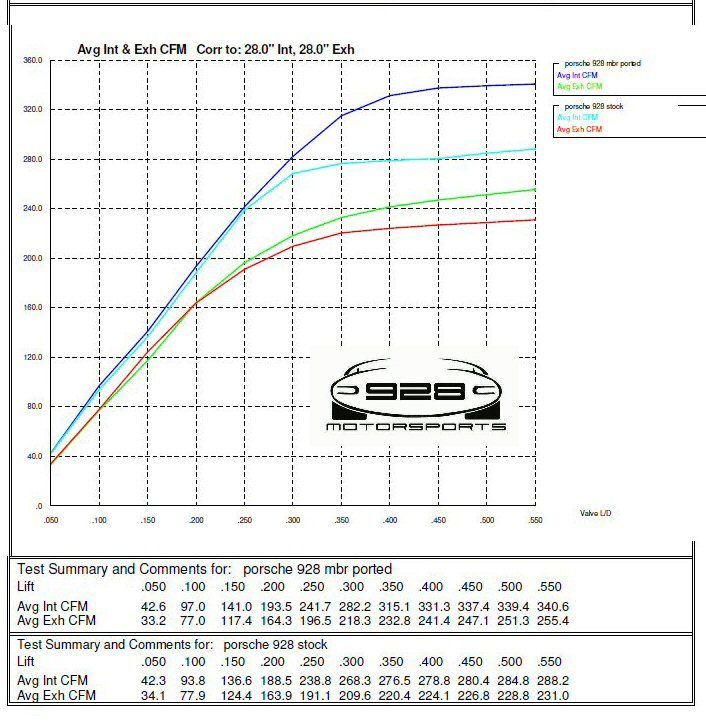
Let's look a the most current airflow information available on this Forum and try to make sense of what it is telling us:
Looks fantastic. The ports themselves look fantastic. However, before you judge the actual result, you need to do some basic calculations. In short, you need to ask....what was the starting point and what was the goal (target/desired result.)
The first thing to realize is that the entire right side of the graph is useless. 928 cams tend to have ~.400" of lift. Showing flow at .550" is a complete waste of time and effort. Makes graphs look impressive, but useless information.
Forget everything above ~.400".
Now look at the left hand side of the graph....everything below .250" of lift is virtually identical. There was virtually zero improvement on the ramps of the cam (where 80% of the time is spent!).
So, going back and looking at this graph, nothing below .250" improved and everything above .400" is useless.
The only increase in flow is between .250" and .400"!
What did that increase do, for this engine? That's the question that should have been answered before all that money was spent....what was the goal?
(Note: Because all my flow work occurs at 10" (previously discussed) what I've learned over the years is all calculated from 10". The flow testing done here was done at 28". The conversion from 28" to 10" is fairly simple.....multiply by .598.)
You want some idea of what horsepower any particular engine has the potential to make, there's a pretty simple (and accurate) formula to calculate this. Each CFM at 10" of water (at peak airflow) will produce .43 horsepower per cylinder...if the rest of the engine is optimized to use this airflow. So the stock head has the potential to make 71 hp (278 x .598 x .43), or 570 total engine horsepower. (That is an impressive stock head, BTW.)
The large port, large valve, head can make 85 hp (331 x .598 x .43) per cylinder, or 680 hp. Again, "potentially".....if everything else is optimized in the engine.
Fantastic, right? Maybe.
So at what rpm will this increased airflow help the engine....that's the real question.
Turns out that this is a pretty simple calculation, also.
RPM= 2200/CID per cylinder x peak airflow at 10".
Doing some quick math:
2200/52 x 198=8375 rpms.
Hang on here. 8375 rpms isn't every going to happen with a 3.750" stroke....even with the very best internal pieces one can find. A road race engine, with 3.750" of stroke, even the very best internal components will survive 7600 rpms....for limited periods of time! The increase in airflow at .400" looks impressive, on a graph, but is useless for this engine.
The good part about it....isn't good. The increase in airflow came at the cost of velocity. Cylinder filling efficiency dropped.
Do the calculations for the stock head in the same engine.
2200/52 x 165 = 7,000 rpms.
The short answer to the original question, above, is pretty simple....considering that the airflow potential through the stock S4 style 928 head is beyond almost any naturally aspirated central plenum engine one can dream up. Forget about increasing valve size and port dimensions....the only thing that is going to happen is a loss of velocity through the port.
The best thing that you can do is very simple....increase the airflow on the ramps of the cam (increase the average airflow) to make more power. Bump the airflow 20% below .250" and you've made some serious improvements! Everything above .250" is a complete waste of time...the head already works fantastic in that range!
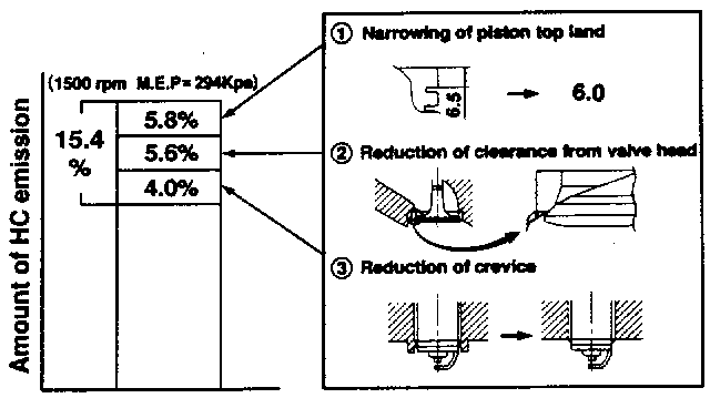
Even for the stock displacement engine, one can try to get the combustion chamber
- to burn better (for normally aspirated engines, this equals burning faster)
- to waste less fresh charge to the exhaust pipe
- to evacuate the chamber of exhaust gasses better
- to reverse less during the overlap
Some ideas from a paper that Mazda engineers wrote below. (This is all theory, but makes sense to me. Use your own brain to assess whether I'm a bull**** artist or onto something.)
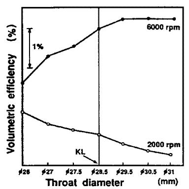
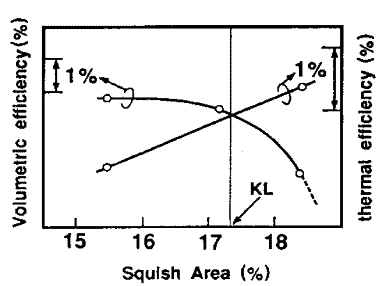
Finding the right compromise on the intake port size:
(Although I doubt that filling the 928 port floor counts as a minor modification...)
Deshrouding the valves while minding the squish area:
It's another compromise here, how well you burn vs. how well you fill.
The small nooks and crannies in the head don't allow the mixture to burn, and that hurts efficiency:
Even if you don't have to get tail-pipe tested, you care about efficiency. But especially if you get tail-pipe tested, eliminating those hydrocarbons may be the difference between passing and not passing with higher overlap cams. And higher camshaft overlap _does_ make usable torque in 928.
Even for the stock displacement engine, one can try to get the combustion chamber
- to burn better (for normally aspirated engines, this equals burning faster)
- to waste less fresh charge to the exhaust pipe
- to evacuate the chamber of exhaust gasses better
- to reverse less during the overlap
Some ideas from a paper that Mazda engineers wrote below. (This is all theory, but makes sense to me. Use your own brain to assess whether I'm a bull**** artist or onto something.)
Finding the right compromise on the intake port size:
(Although I doubt that filling the 928 port floor counts as a minor modification...)
Deshrouding the valves while minding the squish area:
It's another compromise here, how well you burn vs. how well you fill.
The small nooks and crannies in the head don't allow the mixture to burn, and that hurts efficiency:
Even if you don't have to get tail-pipe tested, you care about efficiency. But especially if you get tail-pipe tested, eliminating those hydrocarbons may be the difference between passing and not passing with higher overlap cams. And higher camshaft overlap _does_ make usable torque in 928.
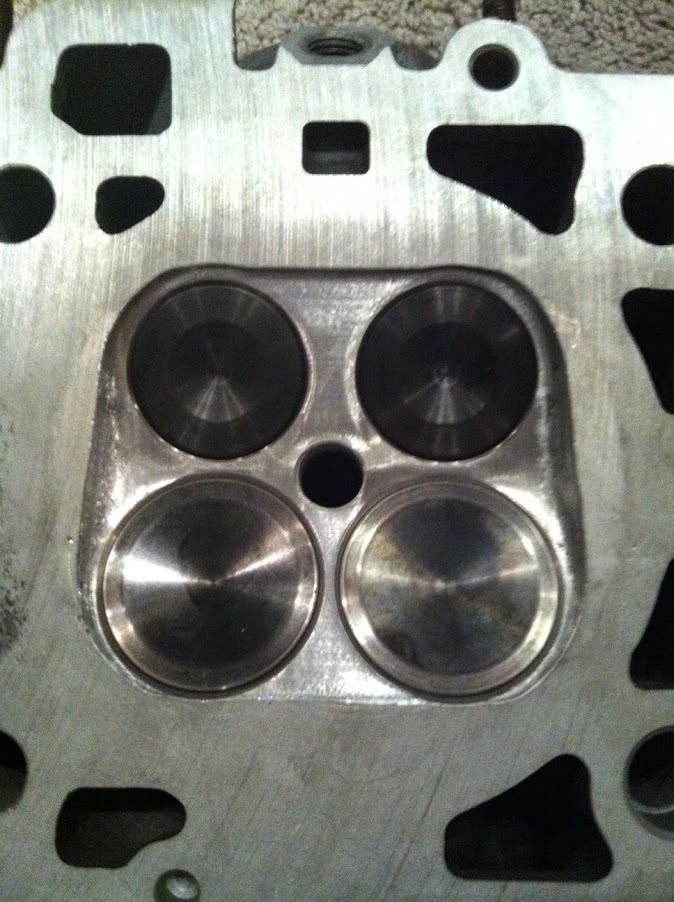
I found that Gerolamy head to be very interesting. If you would be willing to share, I'd love to hear their logic regarding their approach.
I've spent a tremendous amount of time working on the combustion chambers of the 928 head....experimenting with shapes and angles to unshroud the valves. Making changes, testing, making further changes, and more testing. I've worked for hundreds of my own hours with port shapes to increase airflow in the lower lift ranges of the valves....significantly improving airflow below .250". (See my post above, explaining the reasons.)
These efforts have continued to improve my engines. Horsepower continues to increase, without any loss of torque in the mid range.
My street engines are now to the point where they will pass a California emissions test...without a catalytic converter....even with more aggressive camshafts. My HC and CO numbers are virtually zero, with very low NOX....not just to pass an emissions test (as with VW), but in normal operation.
I add converters to my engines....to make them visually legal.....not to clean up the exhaust.
Additionally, all of my clients report significant fuel mileage increases in the highway cruise mode (3-4 more mpg over stock.)
For me, this points towards significantly increased efficiency....brought about by greatly increasing cylinder filling capability and greatly increased combustion efficiency.
It never occurred to me to shroud the valves more....and if I didn't actually see that this had been done, I'd think someone was just messing with me.
Tuomo, the Gerolamy heads you have for the other engine do have much squish area but it would be interesting to know how much the valves shrouding is affected. It is always a compromise between high flow and a compact combustion chamber. It would be interesting to flow one of these intake ports.
�ke
looks like a better-done version of the 99+ Subaru EJ251 SOHC head.
I can't read the head designers' minds, they had their reasons. I can just speculate. Whether my speculations are accurate or have any basis whatsoever or not is anyone's guess.
That said, I think it's mostly about one of the Mazda graphs that I posted.
You trade off combustion efficiency with flow. The Mazda graph says: More squish area, less flow; or less squish area and more flow. Since everyone seems to agree that we have access to more than enough flow, why not make more power from the charge you can trap?
What that head looks like is the Honda IRL head that ended up winning everything. I have a story about those Honda heads, but that's for a later date. With the right kind of piston and bore, these types of heads are going to burn so fast that they can get a very high thermal efficiency.
The valves are not shrouded at low lifts. The valves can flow 360 around the perimeter at low lifts, so they should not have issues at overlap. The designers of this head had very specific cams in mind, so they knew up to what lift cross flow and reversion would be potential problems and beyond what lift those were no longer of any concern. Cams and heads kind of go together like that, you've got to have an least an educated guess of the one before you can make forward progress with the other.
At medium and high lifts, there may be some shrouding. But, importantly, at medium and high intake lifts, when the exhaust valve is closed, the flow appears to be mostly directed to the long side. I suspect this is intentional, because it uses the exhaust valve faces as diffusers to guide the flow to the bore wall. This will result in an efficient tumble motion, especially if combined with the right kind of piston dish.
Combine the efficient tumble motion with ample squish area that breaks the tumble to turbulence, and you'll get a true inferno between 10 degrees btdc and 10 degrees atdc.
I'm curious as to why nobody has converted a 928 to a Miller cycle engine ( same type of combustion cycle as in the Mazda Millenia posted above).
All that is needed is a source of low rpm positive intake pressure.
Plus a set of custom cams with extreme amounts of intake duration to the point where the piston is in the compression stroke and the valve is still open (for around the first 20% of the stroke).
Sounds like a possible option for more power as you can get a lot more air into the engine.

 03-15-2017, 08:38 PM