
Green Wire?
 10-11-2007, 04:10 AM
#46
Rennlist Member
Well, the whole idea of twisted pair wiring is that the transmitter & receiver on either end operate on the voltage differential between wires in a pair rather than absolute voltage, and the idea behind twisting them is that any noise should affect both wires in a pair equally. So if you have common and +5v on a pair, and 1v of noise is introduced, you now have +1v on common and +6v on the other wire in the pair -- preserving the 5v differential, which is the signal.
The green wire circuit is far more primitive, seemingly just a hall sensor and amplification circuitry. So, there is not much signal to begin with, and therefore it can't tolerate much noise before it begins mucking with the threshold at which the box activates the spark. So the cable is shielded where it is in proximity to other wiring.
There is another twist on the story as well. Assume for a second that the hall sensor provides a perfect square wave signal at the distributor female connector for the green wire(it doesn't, but bear with me). Due to the reactance(Inductive and/or capacitive) of the coax cable, the signal shape is changed. Inductive reactance opposes changes in the initial current, Capacitive reactance opposes changes in the initial voltage. So depending on the specifics of the circuit including the coax and the signal, the signal may have a large intial spike or it may roll up to the "high" signal level with a rounded hump -- in any case there is likely a discriminator circuit in the "box" that is calibrated to look for a certain shape to the input signal.
Deviating from the spec impedance on the coax will change the shape of the input signal(whether it will change a significant or measurable amount is another issue). Now, to some degree you can compensate, and you will do so automatically if you are using a timing light, because if the spark is a degree or two early or late you will set the spark to fire at the correct time -- at least, it will be correct at 3,000 rpm, where you set the timing. Since frequency is a factor in inductive reactance and it is an inverse factor in capacitive reactance, and the frequency of the signal changes by an order of magnitude over the RPM range, it's easy to theorize that the effect of the reactance on the shape of the signal will vary over the RPM range. A significant change in impedance could cause the engine to run poorly at one end of the range or the other because of this.
Now, in practice, impedence tends to be more of an issue at higher frequencies(again because frequency is a multiplier in the equation). If you dig up the detailed specs on any variety of coax you will see coax impedance rated at some frequency in the MHz or GHz range. It may not be much of an issue at the frequencies involved in this application, but then again I have nowhere near enough specific info on the circuits involved to do the math. It would be easy enough to hook up a scope and see if there is any observable difference in the signal shape at 1K vs 5K RPM (even numbers to make it easy to compensate on the time scale). Not that the info would tell us a whole lot about what exactly is going on, but if I saw no difference I would have to conclude that the system as a whole isn't very sensitive to a 10x change in impedance.
Anyway, that's all theory and I don't have the time, resources or experience to dig much deeper into the problem. Guys who juggle analog circuits for a living might smirk at the factors I mention which, in their much greater experience, may not matter at all. Some folks, after years in the business, just have an intuitive feel for these things. I'm one of those guys that has the theory but am way out of practice -- I have to chug through the math, measure and analyze and plod away until I get the answer. Analog electronics are half tech and half art/skill -- no two analog circuits operate exactly the same, even if they are built with parts from the same lot. I'm much more comfortable in the DC/Digital regime.
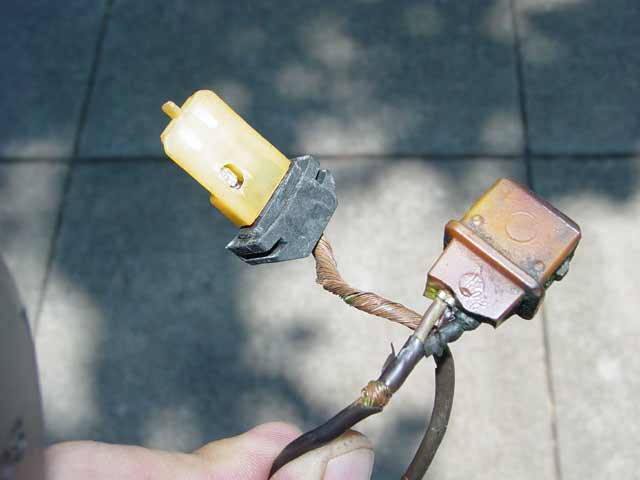
Anyway, here's a pic of what was left of my original green wire. I only have the one pic, and I gave the wire to a guy who needed to tie up his muffler after a funride wreck.
The green wire circuit is far more primitive, seemingly just a hall sensor and amplification circuitry. So, there is not much signal to begin with, and therefore it can't tolerate much noise before it begins mucking with the threshold at which the box activates the spark. So the cable is shielded where it is in proximity to other wiring.
There is another twist on the story as well. Assume for a second that the hall sensor provides a perfect square wave signal at the distributor female connector for the green wire(it doesn't, but bear with me). Due to the reactance(Inductive and/or capacitive) of the coax cable, the signal shape is changed. Inductive reactance opposes changes in the initial current, Capacitive reactance opposes changes in the initial voltage. So depending on the specifics of the circuit including the coax and the signal, the signal may have a large intial spike or it may roll up to the "high" signal level with a rounded hump -- in any case there is likely a discriminator circuit in the "box" that is calibrated to look for a certain shape to the input signal.
Deviating from the spec impedance on the coax will change the shape of the input signal(whether it will change a significant or measurable amount is another issue). Now, to some degree you can compensate, and you will do so automatically if you are using a timing light, because if the spark is a degree or two early or late you will set the spark to fire at the correct time -- at least, it will be correct at 3,000 rpm, where you set the timing. Since frequency is a factor in inductive reactance and it is an inverse factor in capacitive reactance, and the frequency of the signal changes by an order of magnitude over the RPM range, it's easy to theorize that the effect of the reactance on the shape of the signal will vary over the RPM range. A significant change in impedance could cause the engine to run poorly at one end of the range or the other because of this.
Now, in practice, impedence tends to be more of an issue at higher frequencies(again because frequency is a multiplier in the equation). If you dig up the detailed specs on any variety of coax you will see coax impedance rated at some frequency in the MHz or GHz range. It may not be much of an issue at the frequencies involved in this application, but then again I have nowhere near enough specific info on the circuits involved to do the math. It would be easy enough to hook up a scope and see if there is any observable difference in the signal shape at 1K vs 5K RPM (even numbers to make it easy to compensate on the time scale). Not that the info would tell us a whole lot about what exactly is going on, but if I saw no difference I would have to conclude that the system as a whole isn't very sensitive to a 10x change in impedance.
Anyway, that's all theory and I don't have the time, resources or experience to dig much deeper into the problem. Guys who juggle analog circuits for a living might smirk at the factors I mention which, in their much greater experience, may not matter at all. Some folks, after years in the business, just have an intuitive feel for these things. I'm one of those guys that has the theory but am way out of practice -- I have to chug through the math, measure and analyze and plod away until I get the answer. Analog electronics are half tech and half art/skill -- no two analog circuits operate exactly the same, even if they are built with parts from the same lot. I'm much more comfortable in the DC/Digital regime.
Anyway, here's a pic of what was left of my original green wire. I only have the one pic, and I gave the wire to a guy who needed to tie up his muffler after a funride wreck.
 10-11-2007, 06:02 AM
#47
Rennlist Member
Hello Dave,
Twisted pairs are designed to work in balanced systems, and then they do give the interference imunity you describe.
Coax systems are designed to work in unblanced systems, which is what we have in the 928 application.
I am sure that 50 ohm coax would work fine as a substitute for the green wire. The PTFE type of coax I am proposing of course has excellent heat resistance, and so should be a permenent fix.
The problem is getting hold of the connector at the distrributor end in order to make up new leads (Roger, can you source those ?) I can source the male 2 pin at the harness end.
10-11-2007, 09:17 AM
#48
Administrator - "Tyson"
Lifetime Rennlist
Member
Lifetime Rennlist
Member
Excellent info guys!!
Now where do I find some of this? I've never seen cable like that at Radio Shack.
Ok, here is my idea. I'm going the MSD route to try and up the spark on my 81. I would rather power the MSD box with the green wire versus the leads going to the coil since I want to remove the stock Bosch ignition box from the circuit. Problem is, the Bosch box shares it's signal with the tach & the fuel pump.
I'm going to make a short cable with a male / female Bosch connector on each end to go between the green wire and the harness. When I make this cable, I'm going to add another paire of wires tapped into this line that will run to the MSD box, give it the pulse to fire.
This way the Bosch ignition box will keep the tach and fuel pump working.
Assuming this fixes my problem, there are ways to run the tach & fuel pump from the MSD box. For now I want to avoid cutting up the factory harness. One thing at a time.
I might even use an old green wire for the run back to the MSD box. Unless I can find some of the cable John is talking about locally.
My only fear is the two green wires running along side each other might interfear with each other. Is there any type of sleeve you can buy to put wires in that provide further insulation?
Last edited by hacker-pschorr; 10-11-2007 at 09:54 AM.
10-11-2007, 09:48 AM
#49
Drifting
Join Date: Nov 2001
Location: z�rich, switzerland
Posts: 2,233
Likes: 0
Received 0 Likes
on
0 Posts
When I got my new green wire I ran it along the (what do you call it) underbonnet strut (under hood strut?) that runs from side to side of the car to keep the green wire cooler & physically away from the noisy electrics. I also ran it in a clear plastic tube to try to protect it.
Must post a foto when I have time.
Marton
edit not really the foto I wanted but it gives the idea; also does not have the clear plastic tube mentioned.
You can see one of the plastic cable ties that i used to clip it to the strut.
Must post a foto when I have time.
Marton
edit not really the foto I wanted but it gives the idea; also does not have the clear plastic tube mentioned.
You can see one of the plastic cable ties that i used to clip it to the strut.
Last edited by marton; 10-11-2007 at 10:05 AM.
10-11-2007, 10:14 AM
#50
Rennlist Member
Excellent info guys!!
Now where do I find some of this? I've never seen cable like that at Radio Shack.
Ok, here is my idea. I'm going the MSD route to try and up the spark on my 81. I would rather power the MSD box with the green wire versus the leads going to the coil since I want to remove the stock Bosch ignition box from the circuit. Problem is, the Bosch box shares it's signal with the tach & the fuel pump.
I'm going to make a short cable with a male / female Bosch connector on each end to go between the green wire and the harness. When I make this cable, I'm going to add another paire of wires tapped into this line that will run to the MSD box, give it the pulse to fire.
This way the Bosch ignition box will keep the tach and fuel pump working.
Assuming this fixes my problem, there are ways to run the tach & fuel pump from the MSD box. For now I want to avoid cutting up the factory harness. One thing at a time.
I might even use an old green wire for the run back to the MSD box. Unless I can find some of the cable John is talking about locally.
My only fear is the two green wires running along side each other might interfear with each other. Is there any type of sleeve you can buy to put wires in that provide further insulation?
As the wires are screened, there is no problem running them along side each other.
Try to keep the new wire lengths short. Keep the green wires as far as you can from high voltage igntion (and that inlcudes the coil primary.)
You can use any type of TV coax cable for a first try , although this will not be rated for heat.
I have a whole reel of the PTFE stuff if you want some...
10-11-2007, 11:41 AM
#52
Administrator - "Tyson"
Lifetime Rennlist
Member
Lifetime Rennlist
Member
Hello Erik
As the wires are screened, there is no problem running them along side each other.
Try to keep the new wire lengths short. Keep the green wires as far as you can from high voltage igntion (and that inlcudes the coil primary.)
You can use any type of TV coax cable for a first try , although this will not be rated for heat.
I have a whole reel of the PTFE stuff if you want some...
As for the PTFE wire, I sould be able to find some locally, shouldn't I? How rare and/or special is that stuff?
Is there some type if "anti-EMI" shielding you can buy to put a cable into for more protection?
10-11-2007, 01:50 PM
#53
Chronic Tool Dropper
Lifetime Rennlist
Member
Lifetime Rennlist
Member

I'll try using two green wires first, a new one going from the distributor to the factory harness location, then an "old" green wire (on the car now, no issues that I know of) to make the run back to the MSD box.
As for the PTFE wire, I sould be able to find some locally, shouldn't I? How rare and/or special is that stuff?
Is there some type if "anti-EMI" shielding you can buy to put a cable into for more protection?
As for the PTFE wire, I sould be able to find some locally, shouldn't I? How rare and/or special is that stuff?
Is there some type if "anti-EMI" shielding you can buy to put a cable into for more protection?
Anti-EMI shielding is sometimes disguised as steel tubing. Otherwise, as John says, the EMI is drained through the shield on the coax. Coax is rated for % shielding, and there are some double-shielded cables that might do the job.
I would stay away from typical TV coax (RG59 and RG6) since they are solid center conductors, and won't survive long in the vibrations of the engine bay without fracture. IIRC, RG178 is a pretty easy-to-find cable, less than 0.100 dia, and available in PTFE. It would need to be supported well near the ends, as the green wire probebly deserves too.
-----
It wouldn't take me long to start looking at ways to replace those plastic crap connectors with something a little more industrial-strength. If BNC-type connectors could be fitted to the distributor and to the spark box at the other end, one could use one of the many prefab 24" or 36" microvave-rated PTFE 50-ohm connection cables I have in the parts cabinet. The connectors are quite water resistant, with good o-ring seals at the barrel seats. We could add a piece of green heat-shrink to make it all look authentic/original.
10-11-2007, 02:09 PM
#54
Addict
Rennlist Member
Rennlist
Site Sponsor
Rennlist Member
Rennlist
Site Sponsor

You know since the standard coil on the early 928 NEVER sees 12 volts....when starting the coil gets powered through just one resistor BUT in run mode power goes through TWO resistors...why not just have a boost actived switch that increases the power to the coil.....simple easy way to have a BIG spark when you need it ....If you give the coil full 12 volts on a hot day in traffic after 30 minutes it might just explode ....boils the oil and pops the end of the coil  ask me how I know this !
ask me how I know this !
10-11-2007, 02:15 PM
#55
Rennlist Member
Sounds like an interesting project, Erik -- And yes, if you have the ends off the wire you could enclose it in a wire braid sheath then attach the sheath to ground, though as John says this shouldn't be necessary -- especially if you are careful about routing.
10-11-2007, 02:23 PM
#56
Rennlist Member
Dr Bob has some good points..... however be careful of buying RG178.... the type you need is RG178B/U which is rated at 200degC.
But RG178 LSF is only rated 100deg C,a nd RG 178PE only 80deg C.
Here's a source of RG 178B/U in the USA.
http://www.aba-industry.com/aba_coax...e_rf_rg178.htm
The cable is the easy bit, the rela problem is finding a source of new connectors that fit into the dizzy. They don't have a part number on them...
Does anyone have a Bosch part number for the 928 dizzy with green wire ?
10-11-2007, 02:44 PM
#57
Administrator - "Tyson"
Lifetime Rennlist
Member
Lifetime Rennlist
Member
You know since the standard coil on the early 928 NEVER sees 12 volts....when starting the coil gets powered through just one resistor BUT in run mode power goes through TWO resistors...why not just have a boost actived switch that increases the power to the coil.....simple easy way to have a BIG spark when you need it ....If you give the coil full 12 volts on a hot day in traffic after 30 minutes it might just explode ....boils the oil and pops the end of the coil ask me how I know this !
ask me how I know this !I figure the leads going from the MSD box to the coil are less susceptible to interference than the green wire. I'll use 10 gauge (have a 500' spool in the garage) for that run.
10-11-2007, 03:05 PM
#59
Administrator - "Tyson"
Lifetime Rennlist
Member
Lifetime Rennlist
Member
Driver / passenger side?
10-11-2007, 03:56 PM
#60
Chronic Tool Dropper
Lifetime Rennlist
Member
Lifetime Rennlist
Member
Enzo--
Folks who have 500' spools of 10ga in the garage usually have house wiring. That's really stiff due to large fibers, and therefore subject to fracture wherever it bends and flexes. Maybe between your MDS box and the coil there's no flex, but... House wirng in general is not suitable for car stuff. Heat, oil/fuel/solvent resistance don't seem to be up to the duty.
I like using the already-tinned wire that's sold at marine stores. It's fine-strand copper like good auto wiring and has the same insulation ratings, but the tinned copper conductors are way less susceptible to corrosion. Plus they are easy to solder for secure connections. Stuff isn't real expensive, considering how many benefits it brings to a project.