

Devek Individual Throttle Bodies
 03-08-2006, 02:11 AM
#1
Official Bay Area Patriot
Fuse 24 Assassin
Rennlist Member
Fuse 24 Assassin
Rennlist Member
Thread Starter
Question regarding individual throttle body induction systems. I see that Devek has no air flow sensor on their set up. I have also seen many examples which don't have them either. What controls the amount of air going in if there is no air flow sensor?
 03-08-2006, 02:23 AM
#2
Nordschleife Master

Join Date: Sep 2004
Location: Not close enough to VIR.
Posts: 9,429
Likes: 0
Received 2 Likes
on
2 Posts
MAP, manifold air pressure. Instead of measuring the air mass like the MAF on our cars, it measures air pressure and throttle plate position to calculate the mass of the air. At least that's how Louie Ott's setup works.
03-08-2006, 05:02 AM
#4
Racer
Join Date: Feb 2006
Location: Madrid, Spain
Posts: 320
Likes: 0
Received 0 Likes
on
0 Posts
Yes, fairly common in race cars. Gives you instant response. This kind of control is called "throttle-rpm" as you normally build a 2d map with this variables, and then include some "corrections" (Fuel pressure, air pressure, water temp, battery volts...)
The only problem is that you have to control throttle position very precisely to get decent AFR at almost-idle conditions. 1 deg offset may very well ruin your idle (stalling the engine), forcing the driver to keep foot on throttle at stops or adjusting very high idle speed; eventually overheating the engine.
Some setups use this kind of controls in closed loop, thus eliminating this problem, but also all its advantages (but cost).
03-08-2006, 11:16 AM
#5
Captain Obvious
Super User
Super User
Originally Posted by littleball_s4
Yes, fairly common in race cars. Gives you instant response. This kind of control is called "throttle-rpm" as you normally build a 2d map with this variables, and then include some "corrections" (Fuel pressure, air pressure, water temp, battery volts...)
The only problem is that you have to control throttle position very precisely to get decent AFR at almost-idle conditions. 1 deg offset may very well ruin your idle (stalling the engine), forcing the driver to keep foot on throttle at stops or adjusting very high idle speed; eventually overheating the engine.
Some setups use this kind of controls in closed loop, thus eliminating this problem, but also all its advantages (but cost).
The only problem is that you have to control throttle position very precisely to get decent AFR at almost-idle conditions. 1 deg offset may very well ruin your idle (stalling the engine), forcing the driver to keep foot on throttle at stops or adjusting very high idle speed; eventually overheating the engine.
Some setups use this kind of controls in closed loop, thus eliminating this problem, but also all its advantages (but cost).
 03-08-2006, 01:09 PM
#7
Racer
Join Date: Feb 2006
Location: Madrid, Spain
Posts: 320
Likes: 0
Received 0 Likes
on
0 Posts
Originally Posted by Imo000
It doesn�t have to be THAT precise. A lot of cars use a MAP (Manifold Absolute Pressure) sensor instead of a MAF. I have first hand experience with an early FI 5.0L Mustang (86-87), it was an �87 in my case, that had this setup and it�s called a �speed-density� system. It�s a very robust system and contrary to what a lot of people believe, you can even add a supercharger to it and still keep it the original MAP sensor. All I had to do was install a one way check valve into the MAP sensor vacuum line. Even with the supercharger, the Ford 5.0L MAP engine performed excellent. Had a ton of power right from idle to redline. Mine was a basic non-intercooled Paxton system with only an FMU and nothing more.
Trending Topics
03-08-2006, 01:23 PM
#8
Captain Obvious
Super User
Super User
Originally Posted by littleball_s4
I own one of those cars with M.A.P. sensor. It's after the throttle body and the 2d map is manifold pressure + rpm. Not the throttle+rpm control we are talking about, in which is hard to measure manifold pressure after the throttle (as there would be eight sensors in a individual throttle body set up).
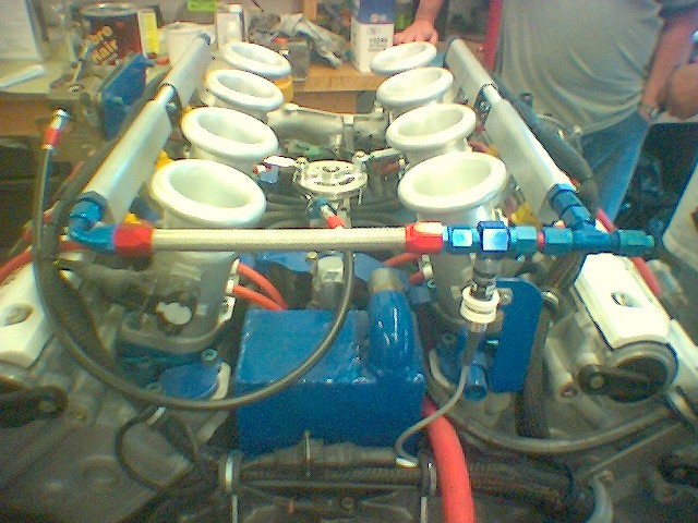
As for the throttle position sensor or sensors. Just like in the picture above, there is no need to have 8 individual throttle position sensors when one is all that�s required. Since all the throttle bodies are linked together and they all open at the same time, one position sensor is all that�s needed.
03-08-2006, 03:11 PM
#9
Three Wheelin'
Originally Posted by Imo000
It doesn�t have to be THAT precise. A lot of cars use a MAP (Manifold Absolute Pressure) sensor instead of a MAF. I have first hand experience with an early FI 5.0L Mustang (86-87), it was an �87 in my case, that had this setup and it�s called a �speed-density� system. It�s a very robust system and contrary to what a lot of people believe, you can even add a supercharger to it and still keep it the original MAP sensor. All I had to do was install a one way check valve into the MAP sensor vacuum line. Even with the supercharger, the Ford 5.0L MAP engine performed excellent. Had a ton of power right from idle to redline. Mine was a basic non-intercooled Paxton system with only an FMU and nothing more.
Jon
03-08-2006, 03:33 PM
#10
Addict
Rennlist Member
Rennlist Member
Join Date: Feb 2004
Location: Monterey Peninsula, CA
Posts: 2,374
Likes: 0
Received 16 Likes
on
12 Posts
Andy,
You need to fab an airbox/plenum that is sealed, and connect it to the MAF if you wish to keep the LH.. It's easy to do this.. The hard part is fitting the size of the plenum you need based on the space you have under the hood, and running a filter that will not be restrictive and rob you of power...
Any competent welder should be able to fab a tank with the 8 holes for the TB openings.. In fantasy land, you could make it out of CF..
HTH,
03-08-2006, 05:04 PM
#11
Addict
Rennlist Member
Rennlist
Site Sponsor
Rennlist Member
Rennlist
Site Sponsor

If you simply run eight hoses off the base of the throttle bodies into a small box you can mount the manifold pressure sensor to the box as well as all other vacuum lines. That lets each individual manifold contribute to the overall vacuum level.
03-08-2006, 06:32 PM
#12
Rennlist Member
Jim's right. The system in my avatar is such a system. I left the original metal injector lines in place to use as the sensor feeds, removed the internals from the metering block & hogged it out with a die grinder. That enabled me to keep the nostalgia look. All the electrics (except the injectors obviously) are hidden. For a V8 the block had to have at least 2 cubic inches of space inside.
Hammer
Hammer
03-09-2006, 12:16 PM
#13
Racer
Join Date: Feb 2006
Location: Madrid, Spain
Posts: 320
Likes: 0
Received 0 Likes
on
0 Posts
Originally Posted by Imo000
I don�t understand what you are trying to describe. I thought we were talking about the same thing (MAP). MAP sensors by nature have to measure manifold pressure so they are located after the throttle body or bodies.
As for the throttle position sensor or sensors. Just like in the picture above, there is no need to have 8 individual throttle position sensors when one is all that�s required. Since all the throttle bodies are linked together and they all open at the same time, one position sensor is all that�s needed.
As for the throttle position sensor or sensors. Just like in the picture above, there is no need to have 8 individual throttle position sensors when one is all that�s required. Since all the throttle bodies are linked together and they all open at the same time, one position sensor is all that�s needed.
1) MAP sensors (pressure sensors) MUST go between throttle bodies and intake valves to measure something that can drive an injection control. I think we agree in that.
2) If you place a single pressure sensor in an individual throttle body, you will measure one pressure drop and you will get a huge error, because volumetric efficiency is not balanced between cylinders, and it moves around with rpm. (see cylinder 7 issue at some sc'd sharks). It's fairly common to see some engines exhaust temps uneven at certain rpms.
If the attached piston looses compression, the throttle flap opens a little more than the rest, get a little air leak in the assembly, the sensor offsets etc the whole engine will become lean and perhaps eventually destroyed. A 5% pressure error when floored will be 5% fuel error: at worst detonation and new engine. When you try to correct this with a vacuum-meter and a computer, what would you do? I think you have to redo the whole map!
3) You can afford a single throttle position sensor, as throttle position does not vary with rpm; and you can just give an offset (mechanically or electronically) every time it goes off tune. Then you syncro the throttle bodies with a vacuum-meter and you go racing. If If the attached piston looses compression, the throttle flap opes a little, get a little air leak in the assembly, etc the attached cylinder will become off tune, but the rest will be ok. A 5% throttle position error when floored will be almost insignificant fuel error. At next throttle syncro service (wich take 15 seconds or so) it will be corrected.
To sum up, a single MAP sensor in a multiple throttle body set up is not the way to go unless you take the measure from 8 cylinders at the same time, using a plenum, and losing the responsiveness we are going for.
03-09-2006, 12:21 PM
#14
Racer
Join Date: Feb 2006
Location: Madrid, Spain
Posts: 320
Likes: 0
Received 0 Likes
on
0 Posts
The way to go (imo) is a throttle-rpm control, slightly corrected lineary with coolant temp, air temp and air pressure outside the car. Easyer and safer if you don't go closed loop with a lambda.