
87S4 no Start
 02-04-2005, 12:59 PM
#121
Addict
Lifetime Rennlist
Member
Lifetime Rennlist
Member
Thread Starter
Originally Posted by T_MaX

LOL, ok the plunger thingy!
 Curtis. Nice diagram. I would love to see how they make them actually.
The car runs great so far. I drove it for the first time last night. Just to the "pub" and back. First thing i noticed is the idle appears to be much better and does not hunt like it did with the 30#. I can actually leave the idle stab. plugged in now and it idles nicely...so far so good atleast. Ill get a better feel for it over the next week or two. . I never really got a chance to get on it fully last night but it seems like the same car as it did with the 30#.
My "glass pack test pipe" goes on today hopefully and my airpump gets unhooked so i will have a better reading on the AF ratio now. Having an airpump upstream of your Wideband sensor doesnt work too well
 .(this was only temporary as i had to smog with my cats and airpump on)
 02-04-2005, 01:31 PM
#122
Rennlist Member
Rennlist Site Sponsor

dr bob asked:
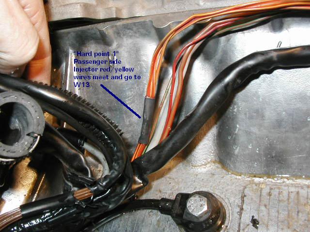
"On the later S4 cars, to make the "shuts one bank down on detected ignition failure" scheme , the nozzle wiring would have to be grouped to the same cylinders that an individual distributor is wired to. Lose fire in one coil, the system drops to four-cylinder mode by stopping fuel to the cylinders that aren't firing. So expecting a common-to-one-side-of-the-engine failure may not be realistic. Is the early S4 injector wiring paired up like the later ('89+) cars with the exhaust temp monitoring [should be]?"
Injectors on earlier cars are wired:
Pin 13 on the LH ECU on one wire to a "hard connector" (in-line splice) to two wires. One wire to an in-line splice, then to 1, 2, 3, 4. The other wire to an in-line splice, then to 5, 6, 7, 8. So, one pin on the LH ECU fires all eight at once by grounding them.
Power is from terminal 87 of the fuel pump relay, thru W13, on two red/green wires, to two "hard connectors" (in-line splices), with one feeding injectors 1, 2, 3, and 4, and the other feeding 5, 6, 7 and 8.
No way to fire injectors except all at one time.
Injectors on later cars are wired:
Pin 18 on the LH ECU on one brown/red wire to "hard connector 2" (in-line splice), then to eight wires, one to each injector. So, the ground connection that fires the injectors fires all eight at once.
Power is supplied by Pin 2 on the Ignition Circuit Control relay on a red/green wire to "hard connector 1", then on four red/yellow wires to injectors 2, 3, 5 and 8.
Power is supplied by Pin 5 on the Ignition Circuit Control relay on a red/yellow wire to "hard connector 4", then on four red/yellow wires to injectors 1, 4, 6 and 7.
So the control is on the power side from the monitoring relay, not on the ground side to the LH ECU. Injectors can be fired in two groups of four (not one bank), but all are fired at the same time.
 02-04-2005, 02:31 PM
#124
Supercharged
Rennlist Member
Rennlist Member
Join Date: May 2002
Location: Back in Michigan - Full time!
Posts: 18,925
Likes: 0
Received 60 Likes
on
34 Posts
I hadn't followed this thread at all, and just finished reading it from beginning to end. VERY COOL! Loved the suggestions. I remember hearing the one should install injectors within a few weeks of having them tested/cleaned so they don't gum up. I guess this is why. Rennlist is awesome!
Tony, when you do finally lay down that BIG GIANT PATCH OF RUBBER, please take a pic of the aftermath! Kewl! (That's 16 years of repressed teenager talking - but please do it anyway!)
Tony, when you do finally lay down that BIG GIANT PATCH OF RUBBER, please take a pic of the aftermath! Kewl! (That's 16 years of repressed teenager talking - but please do it anyway!)
02-04-2005, 02:43 PM
#125
Three Wheelin'
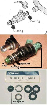
Found this nice injector break-down (guide).
Injector break-down guide
Here is another type

Spray patterns

Replacement parts (general)

Spacer, O-ring and cap orientation
Injector break-down guide
Here is another type
Spray patterns
Replacement parts (general)
Spacer, O-ring and cap orientation
02-04-2005, 07:03 PM
#126
Drifting
Join Date: Feb 2002
Location: Redondo Beach, CA>>>>Atlanta,GA
Posts: 2,015
Likes: 0
Received 0 Likes
on
0 Posts
Whew!...... Glad you got her back on the road.
Out of curiostiy how much time did it take you to remove and replace the manifold/SC/IC, not counting the injector cleaning? I am betting you did it in under 2 hrs?

Andy K
Out of curiostiy how much time did it take you to remove and replace the manifold/SC/IC, not counting the injector cleaning? I am betting you did it in under 2 hrs?
Andy K
02-05-2005, 02:28 AM
#127
Addict
Lifetime Rennlist
Member
Lifetime Rennlist
Member
Thread Starter
Originally Posted by GoRideSno
Whew!...... Glad you got her back on the road.
Out of curiostiy how much time did it take you to remove and replace the manifold/SC/IC, not counting the injector cleaning? I am betting you did it in under 2 hrs?
Andy K
Out of curiostiy how much time did it take you to remove and replace the manifold/SC/IC, not counting the injector cleaning? I am betting you did it in under 2 hrs?
Andy K
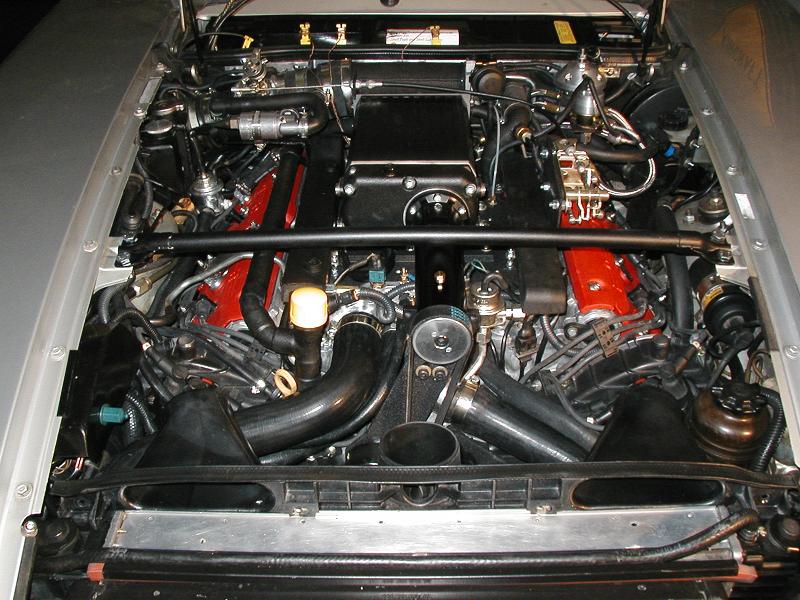
As my engine sits as seen in this pic. to remove the SC takes. 20 minutes. tops. Discalimer being Ive BTDT a few times, so i have my way of doing it all now.
Loosen belt tension..remove belt off pulley
remove 2 snout support bolts
Remove the single set screw on my throttle linkage
Remove bolt on threaded throttle cable and slide cable from the Bracket
remove idles stab hose on the inlet ...downwind side of Throttle body.
Loosen hose clamps on bypass pipe, remove hose from Bypass valve on inlet
Undo boost hose...as a precaution so not to damage the line when re installing
Loosen one large clamp next to throttle body.
remove coolant overflow hose on top of manifold
remove 10 bolts that secure SC/mounting plate to the manifold
Heave it up and slide it a bit to get the the inlet seperated from the throttle body.
thats it. May be different than yours here and there, but thats it.
Heck i may as well keep going.
To take the manifold off.
Depressurize fuel rials.
Remove fuel rail covers
unplug injectors
remove oil breather line at back
loosen 2 fuel fittings at back and one up front
Unplug fuel pressure sender connector
Seperate the intercooler coolant hose...front and aft
Remove injector retaining clamps
Lift up on fuel rail and remove it.
Snip 6 zipties thats secure wire harness along fuel rails.
Remove 3 bolts that hold throttle linkages to bracket.
Remove 10 bolts securing manifold to engine.
Lift up and aft, guiding intercooler hose under the crossover manifold in front.
Done.
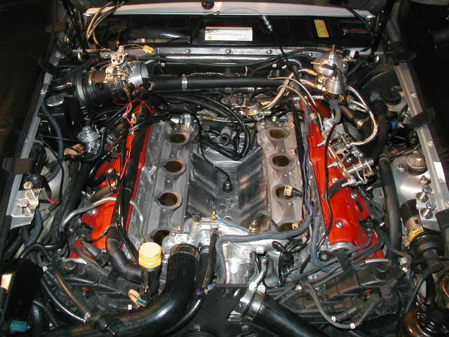
From top picture to bottom picture and back. With out farting around or interuptions. Id give my self 3 easy hrs. Call it 1 off 2 on. Thats just the way i am though.
Last edited by Tony; 02-05-2005 at 03:18 AM.
 12-21-2006, 10:58 AM
#131
Addict
Rennlist Member
Rennlist Member
Join Date: Dec 2003
Location: Houma, LA.
Posts: 546
Likes: 0
Received 0 Likes
on
0 Posts
I had the same issue with my #30 injectors. I had just a few miles on them but they had sat for a year or so. Thanks to this thread I was able to diagnose and fix the injector issue. Here's what I did.
1. Unplug LH Module
2. Unplug an injector (any)
3. Jumper 12 volts and ground to the injector that was previously unplugged (polarity doesn't matter)
4. Listen for a solid click (use a stethiscope or screw driver)
5. Jumper 12 volts and ground to the plug that you took loose in step 2.
6. Listen to the other 7 injectors one at a time. (since the injectors are batch
injected you should hear all 7 fire at the same time)
7. Compare the clicks to each other to find non or poor firing injectors.
I found 5 non firing and 1 poor firing.
I use an end wrench to tap them on the side and was able to get them all firing solid.
Thanks again to all!!!!!
10-22-2007, 12:55 AM
#132
Burning Brakes

Join Date: May 2006
Location: Portland, Oregon
Posts: 809
Likes: 0
Received 0 Likes
on
0 Posts
I had a problem like Tony's after rebuilding my intake. At the same time as my intake rebuild I replaced the in tank and outer fuel pump and the fuel filter, also had the injectors rebuilt. My car wouldn't start... I was suspecting a shorted injector like what Bill Ball had experinced. Ken (Porken) came over to help diagnose and right away we found none, as in 0, of the injectors were firing when we applied 12v directly to the injecotrs. Repeated quick taps of power freed up 5 injectors but 3 were very stuborn and we had to tap on them repeatedly and repeatedly apply quick 12 v charges before they freed up. I didn't think the rebuilt injectors would be stuck like Tony's, he had bought injectors that had been ran for a short period and then not used for a year. Mine were rebuilt about 6-8 weeks ago.
Hope this helps someone.
Hope this helps someone.