

Torque tube rebuild pictures and tools
 01-06-2005, 06:44 PM
#1
Addict
Rennlist Member
Rennlist Member
Thread Starter
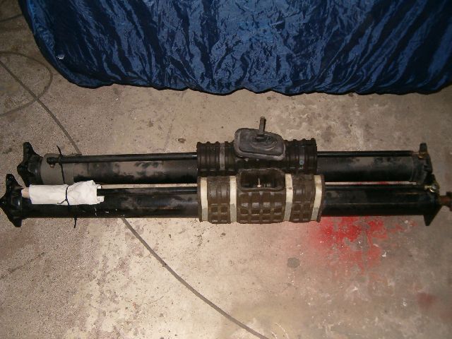
Tools made out of common hardware store supplies are ready and dismantling of '78 5sp tube has been started. Will add more details and better pictures of the tools including pics of mysterious bearing fishing gismo into this thread as work progresses. Just quick update for now, it has been long day. This first post is divided to several parts as number of pictures in one posting seems to be limited to rather small number.
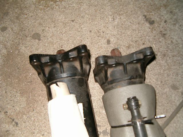
Longer '78 5sp manual tube at front and shorter '92 GTS 5sp tube at the back. Difference in lenght is 30 mm. 1446 mm against 1416 mm. these are of course not totally accurate but measurement error should be within 2-3 mm or thereabouts.
Tubes front mounting plates. Left is '78, right '92. '78's end plate is made out of sheet metal when '92 has cast piece joined to outer tube. On '78 center shaft has moved forward about 5 mm making it impossible to remove clamps rear bolt. Reason for this was loose gearbox input shaft clamp. Shaft 1 (clutch shaft) was pushing firmly against pilot bearing. I think there should be some mm space between pilot bearing inner race and shaft 1's thicker portion to allow shaft 1 & TT shaft package to move slightly forward then heat expands them. They can't move backwards because of gearbox input shaft bearing and other gearbox internals.
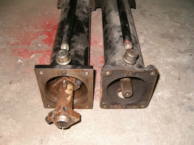
TT rear mounting surfaces. '92 on left and '78 on right. Front mounting surfaces are even.
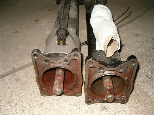
Longer '78 5sp manual tube at front and shorter '92 GTS 5sp tube at the back. Difference in lenght is 30 mm. 1446 mm against 1416 mm. these are of course not totally accurate but measurement error should be within 2-3 mm or thereabouts.
Tubes front mounting plates. Left is '78, right '92. '78's end plate is made out of sheet metal when '92 has cast piece joined to outer tube. On '78 center shaft has moved forward about 5 mm making it impossible to remove clamps rear bolt. Reason for this was loose gearbox input shaft clamp. Shaft 1 (clutch shaft) was pushing firmly against pilot bearing. I think there should be some mm space between pilot bearing inner race and shaft 1's thicker portion to allow shaft 1 & TT shaft package to move slightly forward then heat expands them. They can't move backwards because of gearbox input shaft bearing and other gearbox internals.
TT rear mounting surfaces. '92 on left and '78 on right. Front mounting surfaces are even.
Last edited by Vilhuer; 01-06-2005 at 07:18 PM.
 01-06-2005, 06:48 PM
#2
Addict
Rennlist Member
Rennlist Member
Thread Starter
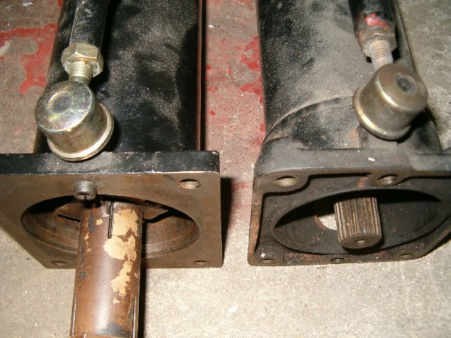
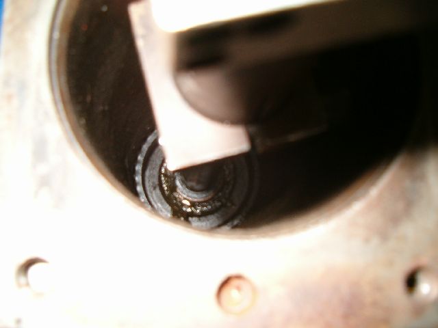
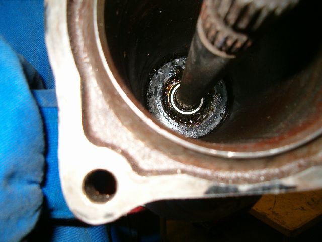
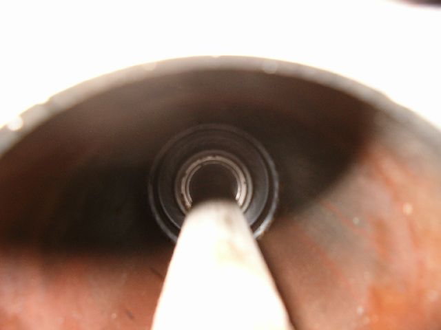
'78 front bearing support inside TT. Clamp is effectively blocking view. Bearing support has it's flat side towards rear making groove (I'll call channel in bearing outer support that for lack of better word) visible towards front. Between bearings inner race and shaft there is thin black plastic pipe. This pipe has other (not visible until removed from torque tube) end larger than bearings inner race so that it will go through bearing only one way and not go throught completely. When sliding center shaft in and out of torque tube this notch holds plastic pipe in place inside bearing as long as center shaft is pushed only one way, from notch side towards smaller side.
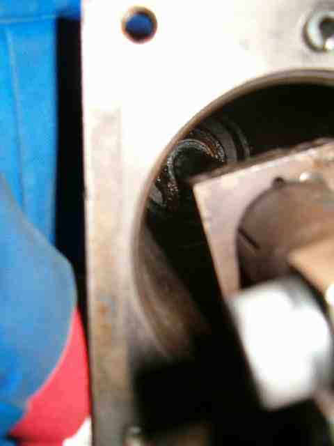
'78 rearmost bearing support inside TT. Black plastic pipe looks thicker than on front bearing. This determines that center shaft needs to be pushed out towards the front. Black stuff around bearing itself is grease added there when TT was on hand last time some two thousand miles ago. Front bearing has it also. It was sorry attempt to increase their service life. Possibly it worked as center bearing is one that's making ugly noicees now and there was no way of adding grease to it back then.
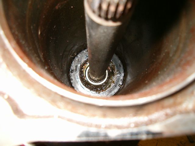
'78 rearmost bearing support inside TT. Black plastic pipe looks thicker than on front bearing. This determines that center shaft needs to be pushed out towards the front. Black stuff around bearing itself is grease added there when TT was on hand last time some two thousand miles ago. Front bearing has it also. It was sorry attempt to increase their service life. Possibly it worked as center bearing is one that's making ugly noicees now and there was no way of adding grease to it back then.
Last edited by Vilhuer; 01-06-2005 at 07:19 PM.
01-06-2005, 06:56 PM
#3
Addict
Rennlist Member
Rennlist Member
Thread Starter
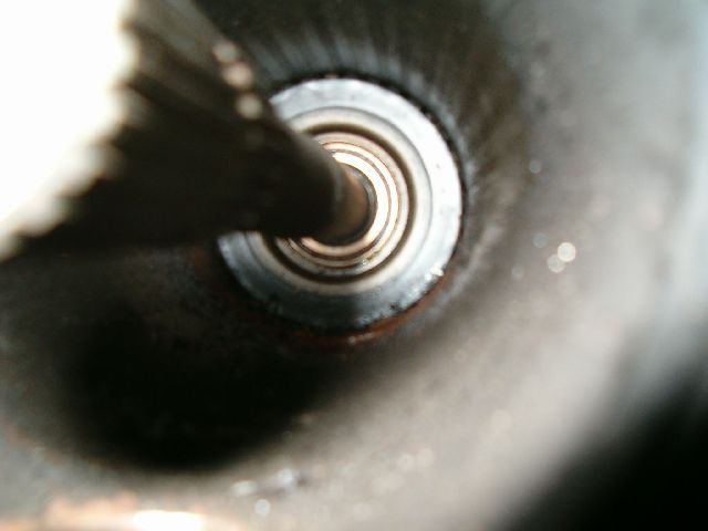
'92 front bearing support inside TT. What is interesting is that bearing support is other way around compared to '78. Groove is towards rear. Luckily plastic pipe seems to be same way as in '78 though. Meaning center shaft needs to be pushed towards front also to keep pipes moving through bearings. This saves some work on making custom tool as exact same tool works on both TT's. No need to make different mounting holes for mounting support irons to front end of TT.
'92 rearmost bearing support inside TT. This support is also other way around compared to '78. Plastic's thicker end is visible meaning both front and rear plastic's point to same direction like they should if one wants to push center shaft through them and not have them move out of bearings.


It would be interesting to hear if there is pattern to bearing support mounting direction. Grooves towards the front or rear of TT? Maybe it was changed for some reason or this is just coincidence that we happen to have them like they are.
'92 rearmost bearing support inside TT. This support is also other way around compared to '78. Plastic's thicker end is visible meaning both front and rear plastic's point to same direction like they should if one wants to push center shaft through them and not have them move out of bearings.
It would be interesting to hear if there is pattern to bearing support mounting direction. Grooves towards the front or rear of TT? Maybe it was changed for some reason or this is just coincidence that we happen to have them like they are.
Last edited by Vilhuer; 01-06-2005 at 07:20 PM.
01-06-2005, 07:25 PM
#4
Addict
Rennlist Member
Rennlist Member
Thread Starter
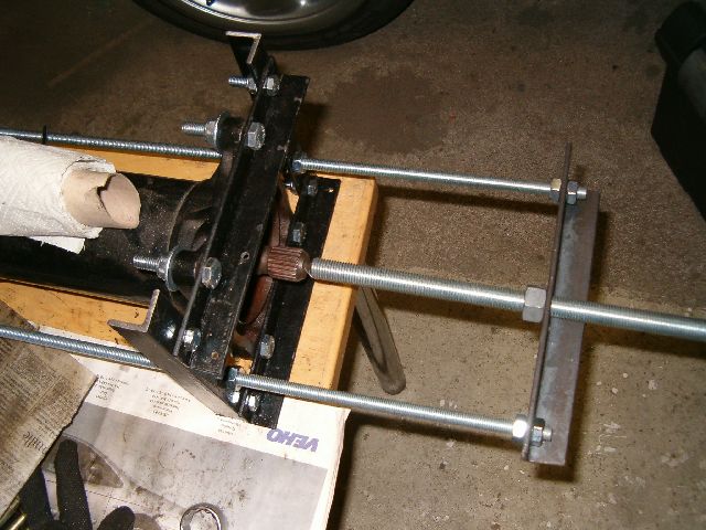
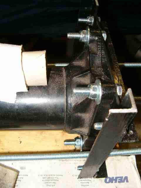
Tool for pushing out center shaft made out of commonly available materials. All that is needed is some flat and/or angle iron, threaded bar, bolts, nuts and washers. In this case we used M16 sized bar as pushing bar and M10 as side supports. M20 as center bar works also and would be better but it's more difficult to join two bars end to end for extending tool longer if needed. Tool in pictures is by no means best possible solution for the job, it's just what I could come up. M16 bars one end is sharpened so that it goes to dimple in center shaft keeping bar centered when pushing. This guarantees bar doesn't start pushing bearing instead as long as pointy end is not allowed to come out of dimple.
Only nut on large M16 bar needs to be rotated to push center shaft out from other end of torque tube. Other way of doing it is by holding nut and rotating threaded bar. We want to do just about everything the hard way and desided not to rotate the bar. When it is rotated while nut pushes it into center shaft this rotates shaft also. I think when center shaft is stationary bearing supports are less likely to start moving inside torque tube. Not sure if this is the case in real life and it doesn't even matter that much as they are coming out anyway.
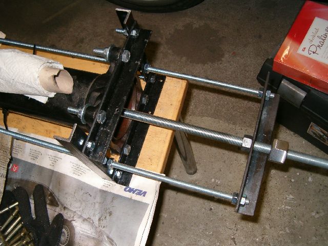
Pictures aren't very good at all. Will get better ones later on. What's not showing in pics is that there is two nuts at other end of threaded bar counterlocked against each other. This provides means of keeping bar stationary when single nut next to support iron is turned. Other, and easier, way would be to keep nut next to iron stationary and turn two at the end.

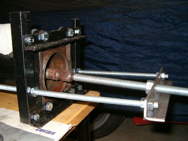

Only nut on large M16 bar needs to be rotated to push center shaft out from other end of torque tube. Other way of doing it is by holding nut and rotating threaded bar. We want to do just about everything the hard way and desided not to rotate the bar. When it is rotated while nut pushes it into center shaft this rotates shaft also. I think when center shaft is stationary bearing supports are less likely to start moving inside torque tube. Not sure if this is the case in real life and it doesn't even matter that much as they are coming out anyway.
Pictures aren't very good at all. Will get better ones later on. What's not showing in pics is that there is two nuts at other end of threaded bar counterlocked against each other. This provides means of keeping bar stationary when single nut next to support iron is turned. Other, and easier, way would be to keep nut next to iron stationary and turn two at the end.
Last edited by Vilhuer; 01-07-2005 at 02:49 AM.
01-06-2005, 07:34 PM
#5
Addict
Rennlist Member
Rennlist Member
Thread Starter
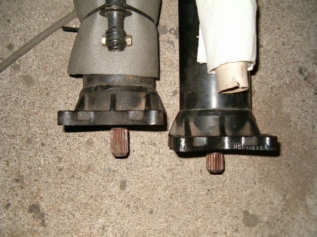
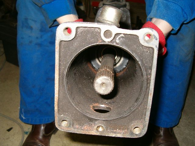
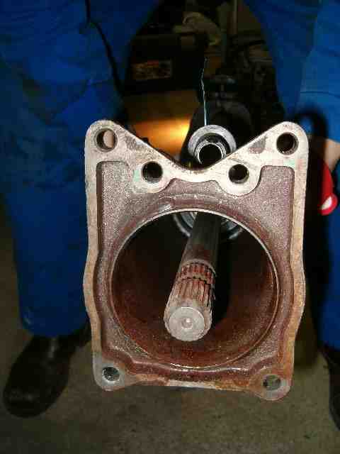
Here's status as of now. Large nut on other side of support iron isn't there for any other reason that that it was left there unintentionately. It's coming out first thing next nut turning session.

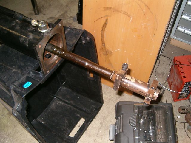
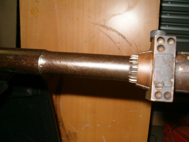
Thinner part of shaft is needed to make room for clamp to move back when removing shaft 1 as part of clutch removal. AFAIk this is the place that twists and snaps when center shaft fails. Brown stuff on part of shaft is just grease from front bearings side that shaft has picked up.
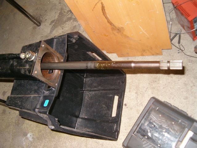
That's if for tonight.
Thinner part of shaft is needed to make room for clamp to move back when removing shaft 1 as part of clutch removal. AFAIk this is the place that twists and snaps when center shaft fails. Brown stuff on part of shaft is just grease from front bearings side that shaft has picked up.
That's if for tonight.
01-06-2005, 07:56 PM
#6
Drifting
Man you can make things complicated! I wrote up how to rebuild your own torque tube a couple of years ago including how to build a tool easily that is about 1/3 as complex as yours. I have used it sucessfully for over a dozen torque tubes with minimal problems.
But the spirit lives on. It's amazing how simple some things can be when someone takes the time to just look at them. If you have any questions, feel free to ask. I don't have my writeup on this computer or I would send it to you. They are not hard to rebuild if you don't mind some repetitive motions. Now where did I put that ratcheting open ended wrench?
Dave
Motorsport

Trending Topics
01-06-2005, 09:04 PM
#8
Gluteus Maximus
Rennlist Member
Rennlist Member
Join Date: Nov 2004
Posts: 6,365
Likes: 0
Received 0 Likes
on
0 Posts
Originally Posted by Ketchmi
Man you can make things complicated! I wrote up how to rebuild your own torque tube a couple of years ago including how to build a tool easily that is about 1/3 as complex as yours. I have used it sucessfully for over a dozen torque tubes with minimal problems.
01-06-2005, 09:53 PM
#9
Drifting
I will e-mail it to whoever needs it, after I find it on my computer. A friend was hosting it on his website but probably needed the room. (BJ?)
Dave
Motorsport
Dave
Motorsport
 01-07-2005, 03:08 AM
#11
Addict
Rennlist Member
Rennlist Member
Thread Starter
Dave, I'm fully aware this is overengineered solution and can think of about dozen different ways requiring much less parts. Already had all angled irons cut to lenght including some holes in them left over from different project so it wasn't that much work to make the skeleton structure. Please post you version so that all who are tackling the job have more ideas how to do it. In your over dozen cases have you seen any pattern which way bearing support were originally mounted?
 01-07-2005, 03:11 PM
#15
Racer
Join Date: Jun 2003
Location: McDonough, Ga.
Posts: 369
Likes: 0
Received 0 Likes
on
0 Posts
Dave (Ketchmi) This looks like your writeup. Found the link from Nichols site.
http://home.comcast.net/~gq-beej/928/ttrebuild.htm
http://home.comcast.net/~gq-beej/928/ttrebuild.htm