
Oil Separator breather design
 08-18-2004, 02:33 AM
#1
Addict
Lifetime Rennlist
Member
Lifetime Rennlist
Member
Thread Starter
It sure feels good to get under the hood of my car again. ive been away from "the obsession" (as my wife calls it) for nearly 2 months, due to vacation, work....and being Married with children(that by itself will kill A LOT of time)
Anyway...
Im having this "thing"made below.
Since the autorotor SC that Andy uses sits directly over the stock filler neck, one has to come up with another way to get oil into the motor. Andy provides a plate and a fitting and some hose that I know works, but i want a dual purpose device.
1) source to fill oil and 2) a means to help separate the oil mist from the air before it travels up to the breather piping/system.
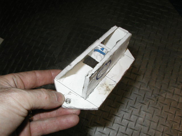
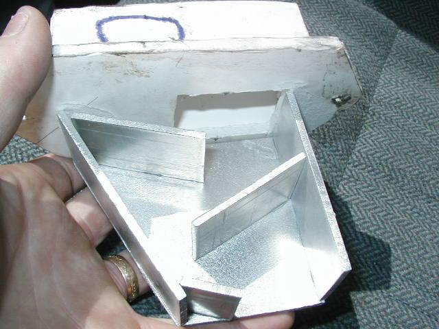
Below is what i had originally made up from card stock..
Then i went to the IOC and saw what "Professer Fire Breathing" Ott had on his soon to be stroker. (the blue object below....cool or WHAT!!)
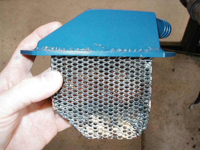
He uses windage tray material and fab'd a "box" that holds what amounts to a copper scrub pad! The oil mist that is supsended in the air that passes up through the filelr neck/breather gets entangled in the copper "fibers" and much of it falls out of suspension and drains back down. Thats the theory at least.
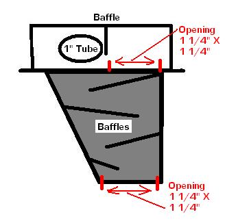
I decided, for the saking of trying my own idea and not to keen on putting copper fibers above my crankshaft, to just install a series of angle "baffles". This should be very similar in principle to an inertial separator that i have seen on the Turbo-Prop airplanes Ive flown. The oil being heavier than the air cant make the turns and thus gets trap and falls out of suspension...and drops.
This is a crude schematic i did.
from this i cut my own aluminum and tacked it in a few spots with a super glue called ZAP.
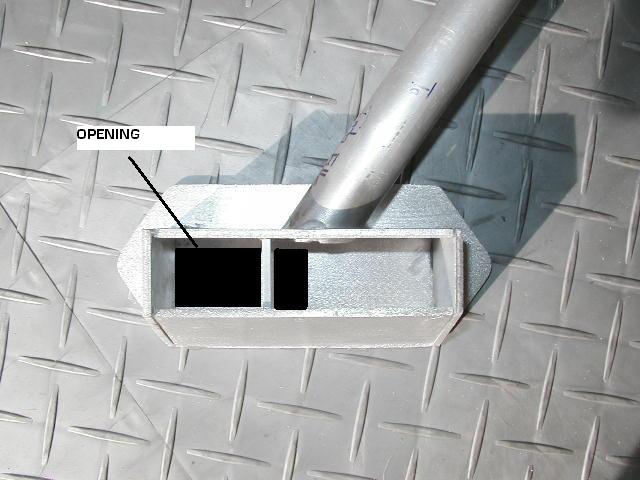
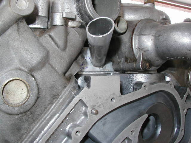
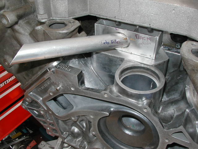
The long tube is angled upward so when oil is added to the motor it still runs "down hill" to it and doesnt accumulate in the passage ways.
Anyway, i have it all cut, and superglued togther so the welder can tack it easy. (found a GREAT welder BTW Andy, thanks for the offer though) As you can see I dont have much room to work with and this is the reason i supergled/tacked the parts in postion for the welder. This way he should be able to tack it up with out stuff moving.
Anyway...any input or ideas. Im pretty much gong with it, but just want some thoughts.
Its a 1" pipe/filler, that will also tap into the rest of the breather assembly on the motor...and end up in a catch can...and perhaps drain back to the pan( not sure yet)
Does anyone know if thay make that windage material in Aluminum?
This whole breather thing is a bit over my head and Ive seen propbaly a dozen or more different setups and ways to do it on the 928! one more cant hurt!

Anyway...
Im having this "thing"made below.
Since the autorotor SC that Andy uses sits directly over the stock filler neck, one has to come up with another way to get oil into the motor. Andy provides a plate and a fitting and some hose that I know works, but i want a dual purpose device.
1) source to fill oil and 2) a means to help separate the oil mist from the air before it travels up to the breather piping/system.
Below is what i had originally made up from card stock..
Then i went to the IOC and saw what "Professer Fire Breathing" Ott had on his soon to be stroker. (the blue object below....cool or WHAT!!)
He uses windage tray material and fab'd a "box" that holds what amounts to a copper scrub pad! The oil mist that is supsended in the air that passes up through the filelr neck/breather gets entangled in the copper "fibers" and much of it falls out of suspension and drains back down. Thats the theory at least.
I decided, for the saking of trying my own idea and not to keen on putting copper fibers above my crankshaft, to just install a series of angle "baffles". This should be very similar in principle to an inertial separator that i have seen on the Turbo-Prop airplanes Ive flown. The oil being heavier than the air cant make the turns and thus gets trap and falls out of suspension...and drops.
This is a crude schematic i did.
from this i cut my own aluminum and tacked it in a few spots with a super glue called ZAP.
The long tube is angled upward so when oil is added to the motor it still runs "down hill" to it and doesnt accumulate in the passage ways.
Anyway, i have it all cut, and superglued togther so the welder can tack it easy. (found a GREAT welder BTW Andy, thanks for the offer though) As you can see I dont have much room to work with and this is the reason i supergled/tacked the parts in postion for the welder. This way he should be able to tack it up with out stuff moving.
Anyway...any input or ideas. Im pretty much gong with it, but just want some thoughts.
Its a 1" pipe/filler, that will also tap into the rest of the breather assembly on the motor...and end up in a catch can...and perhaps drain back to the pan( not sure yet)
Does anyone know if thay make that windage material in Aluminum?
This whole breather thing is a bit over my head and Ive seen propbaly a dozen or more different setups and ways to do it on the 928! one more cant hurt!
 08-18-2004, 04:00 AM
#2
Drifting
Join Date: Feb 2002
Location: Redondo Beach, CA>>>>Atlanta,GA
Posts: 2,015
Likes: 0
Received 0 Likes
on
0 Posts
Tony,
One distinct advantage to just putting a plate there with a fitting is ...potential. If, by chance, you come up with a design that is not the absolute greatest that could possibly be ever in existance, you won't have to remove the SC snout and water bridge to change it. For example you realize the small ammount of blow-by mist and gasses will separate and condense faster if they are cooled down somehow. Then you realize you have a constant supply of "cool" water from an intercooler. Then you realize using a catch can/separator cooled by the water flowing through the IC would be the ideal method of getting everything out of the small amount crank case blow-by air before routing it to the smog pump to create a vacuum in the crank case adding HP. All you'll have to do is route the hose from the fitting to the watercooled blow-by mist and gas condensor/catch can that erveyone that bought my systems will recieve.
Some data on the stock oil breather I recently gathered..... There are 3 hoses that come off the stock oil filler neck. One is 12 mm ID and just goes to the PS cam cover. It vents the crank case to the cam cover. One goes to the intake. The actual ID of this opening is 5.5mm or just under 1/4th inch AND it is restricted. It will only open at about .5psi pressure. This 5.5mm opening is the only place the crank case is actually vented not back to inside the engine. The third, very small at the top of the neck, provides no venting and is just part of the fuel tank venting sytem for emissions. Therefore the entirety of the crank case venting of the stock S4 is restricted to the 12mm opening of the rear PS cam cover fitting and the 5.5mm ID opening on the filler neck that opens under pressure. Using a 1" opening such as the the plate and fitting I provide, gives over 5x the total crank case venting of stock since the front cam cover fitting is now venting instead of recieving.
HTH,
Andy K
08-18-2004, 04:41 PM
#4
Addict
Rennlist Member
Rennlist Member
Join Date: Jul 2003
Location: SUNNY SO-CAL
Posts: 219
Likes: 0
Received 0 Likes
on
0 Posts
Tony...that looks great. I do believe that there is aluminum mesh out there that you would be able to incorporate into your design. To bad that won't work for us Vortech guys.
08-18-2004, 05:38 PM
#5
Addict
Rennlist Member
Rennlist Member
I believe anyone could use Tony's design if they simply left off the portion on the top side of the mounting plate. The baffles and plate can then be sandwiched below the stock oil filler neck by using a stock gasket on each side. I fabricated a simpler baffle for my 1980 to hopefully help control the oil injestion problem. Seeing Tony's design now, I think it would work much better than mine.
Trending Topics
08-20-2004, 03:56 PM
#8
Addict
Lifetime Rennlist
Member
Lifetime Rennlist
Member
Thread Starter
Originally Posted by GoRideSno
Looks good.
Watch out though Tony, you'll be hooked on getting cool stuff made just like I have become.
Andy K
Watch out though Tony, you'll be hooked on getting cool stuff made just like I have become.
Andy K
I tell ya Andy, your not kidding! With cad, a good welder, some time and the enjoyment i get out of designing and building "stuff" Ive only just begun! Its really is cool to come up with an idea, design it, find the raw materials, then have some one build it for you. Each one of those steps has been very time consuming. Now that i have found my sources for stuff around town, its much better. It sucks drving and calling around trying to find materials..parts..people to do a job for you....and then not have them mess it up! Again , hats off to you, murph and john for the work and time youve devoted to this boosting thing.
Now, I only WISH i could weld, specifically aluminum. I really would be set! Ive been watching the guy work on some of my parts and its a pretty cool thing. An art!
08-20-2004, 04:09 PM
#9
Drifting
Join Date: Feb 2002
Location: Redondo Beach, CA>>>>Atlanta,GA
Posts: 2,015
Likes: 0
Received 0 Likes
on
0 Posts
Tony,
You're on a dangerous path. I'm going to have to call an intervention.
Just wait until you realize you can e-mail a DXF file to a MFG facility and have a part from they in less than 24hrs.
I have something like 200-300 CAD drawings.
Andy K
You're on a dangerous path. I'm going to have to call an intervention.
Just wait until you realize you can e-mail a DXF file to a MFG facility and have a part from they in less than 24hrs.
I have something like 200-300 CAD drawings.
Andy K