When you click on links to various merchants on this site and make a purchase, this can result in this site earning a commission. Affiliate programs and affiliations include, but are not limited to, the eBay Partner Network.
The PSD system is back in the GTS. I used the clutch pack from my late 90S4 transaxle diff- it appeared to be in perfect condition with no measurable wear- the plate pack height was 34.5mm which is perfect. The clutch basket is 34.1mm deep so when assembled there is a slight compression which according to Porsche should take 5NM to break the grip and that is exactly what I measured. The taper bearings were fine but I fitted new O rings [3mm x 110mm]. The bearing is a common size nominally 50x80x20 and such sizing is very common however the designation is XAA 32010X as made by Timken and those numbers apparently do have significance in the specification as advised by the UK Timken agent. The shaft seal is a double lip seal – the ones I acquired are made by SKF model CR48x65x10 HMSA10RG.
The slave cylinder from the GTS had serious body corrosion so is not useable as it stands but I believe a repair is possible. I used the body from my 90S4 slave cylinder and the piston from the GTS unit. Both conrods were in poor condition so I used the one I had made locally. Installing the replacement seals was not difficult- I heated the piston and the PTFE central seal in boiling water however I did not like the feel of the installed condition and wonder whether it will in fact seal without losing hydraulic fluid- time will tell!
Studying the documentation and the system in detail I learned rather a lot about the PSD system design and operation. I also got back into my books and studied how to design O ring seal systems. I now have what I perceive to be a superior piston design in mind- hopefully it will not be needed.
Using the Louie procedure bleeding the system was a doddle and everything seemed to work as expected. I now have a couple of non PSD tasks to do then can test it. I also intend to see if I can get the GTS PSD clutch friction plates re-lined as a back up.
Hi Fred - If you took any pictures of the clutch pack and stuff, please post them. In all my years on Rennlist, I don't recall anyone ever posting pictures of PSD guts. And Lord knows the drawings in the WSMs could be better
BTW - Did you replace the baffle seal (the one that keeps brake fluid from leaking in the top of the transaxle?
Hi,
I can and will be happy to post all kinds of info and pics for anyone interested. Just have to upload the photos
to my laptop. I made copious notes as I investigated and checked things.
Indeed I replaced the bellows.
Hi Fred - If you took any pictures of the clutch pack and stuff, please post them. In all my years on Rennlist, I don't recall anyone ever posting pictures of PSD guts. And Lord knows the drawings in the WSMs could be better
BTW - Did you replace the baffle seal (the one that keeps brake fluid from leaking in the top of the transaxle?
Mr NV,
Some pics of the PSD diff unit herein. There is nothing in the WSM that shows this kit- the WSM entry is more a diagnostic approach rather than an assembly guide but to be honest there is not that much to it that needs such and most of what is shown for the basic diff applies just the same or so it seems to me.
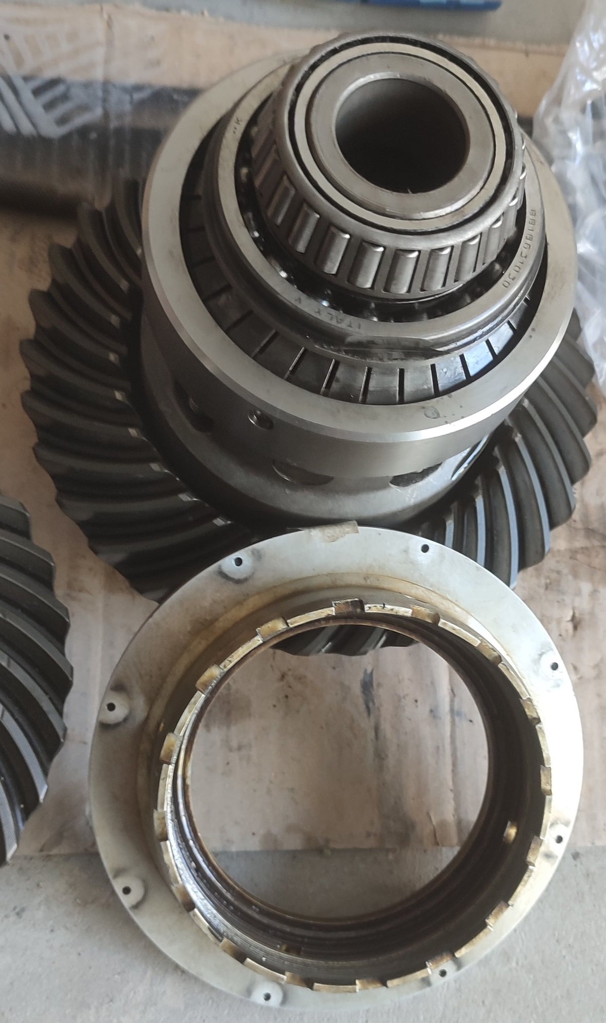
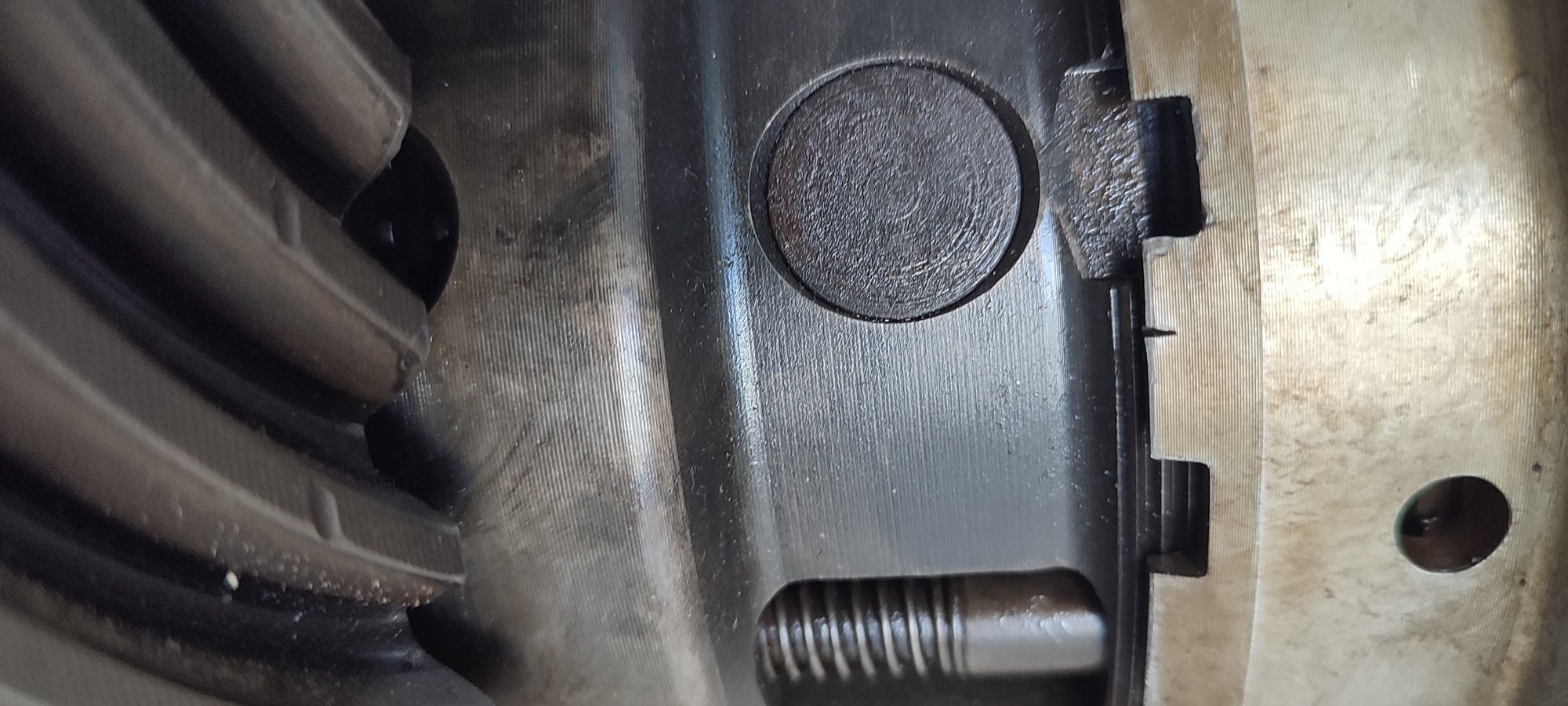
The first pic below is what you see when the diff cover is removed. To get the diff unit out the bearing supports have to be removed and the pivot arm positioning bolt needs to be backed right off. I marked the bearing supports such that I could put them back in the same position/orientation and upon removal I measured the shim packs/individual shims so that I knew exactly what went where. The orientation of the bearing carrier is also partially critical in that it is a hexagon affair and three sides have additional casting flashes- get these out of phase and the pivot arm tensioning bolt cannot be engaged.
The GTS diff unit I just opened.
In the bottom right you can see the adjusting bolt as it engages the pivoting release arm. I concluded that there is no real reason for the adjustment range it has and a fixed length bolt would probably have sufficed but it is what it is. I reinstalled mine exactly as it came out and in this position there is a float of about 2mm to 3mm. The slave cylinder conrod pushes against the opposite end of the release arm causing a uniform "push" on the clutch bearing. In the centre of the unit you can see one of the four spring loaded clutch thrust pistons- these 4 pistons push against a thrust plate in the base of the clutch basket. The clutch bearing results in a 4:1 reduction ratio such that slave cylinder forward motion of 1.2CM is reduced to 0.3cm of movement compressing the clutch pack and that takes the lock from zero % to 100%.
Next photo shows the GTS diff assembly out of the casing:
GTS diff unit showing clutch tensioning mechanism
The slave cylinder conrod pushes against the release bearing arm and that in turn pushes against the release bearing and then those fingers reduce the axial movement in the 4:1 ratio I reported earlier.
The next photo shows the crown wheel mounted-
Crown wheel bolts
The Crown wheel is secured by 12 x 20mm bolts torqued to 108 ft lbs. The locking tabs have to be replaced after removal and the U shape has to be compressed inwards to form a "horse shoe" shape that locks them in place - then two sides are folded over to lock the bolts. When the bolts are removed the Crown wheel can be removed. On the GTS unit the crown wheel slips over the locking basket- on the 90S4 unit the locking basket has a flange that catches the crown wheel but prevents removal until the assembly is removed. I dismantled the spare 90S4 unit but no need for the GTS unit.
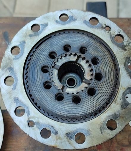
Once the drown wheel is removed there are two small counter sunk grub screws that need to removed that sit in the face that was previously covered by the crown wheel. Once they are removed that bearing plate can be lifted off and that exposes the clutch basket.
Next photo is the clutch basket exposed:
Clutch basket with some plates still present
This photo is the 90S4 clutch basket with some of the plates still mounted. The 90S4 has 10 friction plates of two different types- 5 of them have full face friction material and are 1.8mm thick, 5 of them have donut friction faces and are 2.4mm thick. The carrier plate for the friction material is 1.0mm thick. The 90S4 also has 9 plain plates - 8 of them were 1.5mm thick and one was a bit thicker to give a total clutch pack plate build height of 34.5mm- this dimension is critical and the pack needs to meet this height to achieve the correct construct when new. Interesting how the fancy factory tool that costs about about $1k on a new plate pack gives a reading a 34.5mm even though it cannot see the plate pack. In reality it is little more than a very expensive dipstick that with the slave cylinder removed, can thus measure by inference the plate pack wear. When the depth increases by 10mm the plate pack is presumed to be worn out. Thus that 10mm of slave cylinder conrod movement translates to 2.5mm of total clutch friction plate wear. So, for the S4 plate pack the 10 friction plates each have a friction material layer of 0.4mm each side, 0.8mm thickness per plate and 8mm of overall friction material in the total pack. Thus Porsche designates they are worn out when the height of the pack reduces by 2.5mm and assuming uniform wear, 5.5 mm of friction material would still remain. That sounds very conservative to me.
Anyway to summarise: the slave cylinder appears to have a total stroke of 25mm, 12mm of movement is needed for zero to 100% lock up, 10mm of that stroke is needed for wear and 2mm to 3mm is available for "float". Not difficult to understand why correct calibration is needed!
Next photo shows my 90S4 diff with the adjustment ring removed
90S4 diff unit with bearings removed and clutch tensioning ring removed
This photo shows the clutch tensioning system, the pistons, the locking tab. When removing the cover, the fingers have to be taped up or else you end up with the job lot all over the floor- ask me how I know! In this photo one can clearly see two of the clutch tensioning pistons running through the casing.
Next photo is the damaged GTS clutch pack:
Damaged GTS clutch pack
The GTS has 8 friction plates and 7 plain plates. All 8 plates appear to be the same and given the pack needs to have a total height of 34.5mm the inference is that the 8 friction plates have a thickness of 3mm, the 7 plain plates are 1.5mm and this would give a total build of 34.5mm. When this plate pack was removed the total height was something like 38mm and the friction plates had swollen to something in the region of 3.3mm each plate. On most friction plates the friction material had demounted from the plate on either one side or in some cases both sides- only one plate remained intact!. Needless to say the additional compression of 3.5mm was more than enough to lock the diff solid and that was precisely what i experienced.
It would seem Porsche were not happy with the 90S4 friction plates and hence the modifications made. The clutch pack from my 90S4 was seemingly in perfect condition with no signs of wear. The 90S4 had covered some 120k km when i lost it. Under normal running and especially with wider/stickier tyres the PSD system has less work to do.
This is the clutch basket with the central pinion removed showing the diff cogs. Note the 4 pistons in the base that move forwards by up to 3mm to achieve full lock up. The position of the piston tips is such that they should sit flush with the base of the basket. Above this sits a very solid pressure plate that pushes evenly into the clutch pack thus compressing it.
Next photo- the GTS diff unit with the S4 tensioning plate for comparison
The GTS unit is neater- the S4 unit below can catch the crown wheel if it drops when all the bolts are released. The GTS unit ahs the advantage that the crown wheel can be removed and put to one side which in my case nothing further had to be done.
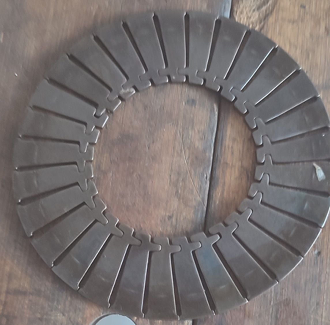
Next photo shows the clutch engagement fingers:
Clutch engagement fingers
The fingers can only be released as and when the passenger side bearing is removed. I did not need to do this on the GTS unit and this item came from the 9S4 unit. 7777To handle this item one has to use some masking tape to hold it all together when the release bearing is removed. Even if one drops them all over the deck it is not really a problem as long as one has all the fingers. These fingers translate the slave cylinder conrod movement such that 12mm of working travel reduces to the 3mm of clutch compression needed. A simple but very clever design I would say.
Next photo is the clutch basket when full showing the S4 plates
Clutch basket full of plates
This is what the clutch basket looks like when fully loaded with plates. There is a spacer that sits in the centre of the pack to leave things flush as it were. Note the S4 plates have ribbing whereas the GTS plates seemingly do not. The plate one sees in this photo is the full face plate of 1.8mm thickness. The thicker [2.4mm] plate has a donut profile rather than full face- why they are different is beyond me! Anyone any suggestions?
Assembling the diff unit and installing it is a relatively straight forward affair. The tensioning ring for the 4 pistons is a simple "screw down by hand" affair and as far as I am concerned it is positioned such that the pistons are flush with the base of the clutch basket. The critical bit is placing the locking tab in the nearest of the peripheral serrations. On my spare unit it took about 6 complete rotations to engage to the correct position. The next photo shows the locking tab in-situ.
Locking tab
Installation of the diff unit into the casing was a little tricky due to cramped access and the weight of that thing [20kg+?]. The trick bit is to ensure the tensioning pin in the lower rear passenger side of the diff casing is fully retracted and the release arm sits correctly [orientation and alignment] in the detentes on the release bearing face. Needless to say the release arm has to be the right way round!
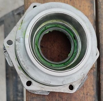
For the half shaft seals I applied a couple of tips I read about during my literature search. The first one was to pack the annuus containing the retaining spring with a heavy grease [I use a green coloured MB grease for my wheel bearings- it never dries out]. Apparently these springs can easily drop out if not careful/aware of the problem and if that happens the service life of the seal will be reduced drastically. The other tip was to pack the recess between the primary and secondary seals with grease as well. This helps stop crap from getting in there and causing damage. The secondary seal is the most outboard face and is designed to help protect the primary seal.
Seal greased and ready for installation
Next photo shows how I installed the bearing carriers
Bearing carrier
To facilitate installation of the bearing carriers I made some studs from 8mm studding. The intent was to provide a guide during installation. I simply used gentle/even persuasion with a rubber mallet. I also lubricated the mating face and found the carriers engaged very easily taking care to ensure the diff unit male race engaged the female outer race cleanly with no binding. Once the bearings have engaged such that the O rings are no longer visible the regular fasteners can then be engaged, the temporary studs removed and then torque the job lot up correctly and evenly- 22 ft lbs as I recall. Then engage the positioning bolt in the original position it was found in.
The final step was to fit the rear most diff cover. I used a new paper gasket- good idea to order two of these- I wrecked one of them - they are very flimsy. I fitted them dry and found it very tricky to install- the trick was to hold the gasket in place in several locations with some baling wire, start a few more bolts elsewhere on the periphery and then remove the wires. Like a dork I forgot to order new sealing washers for the drain and level/fill plugs so I used the items i removed and seated them with copious amounts of PTFE tape.
I also noticed another interesting difference between the 90S4 unit and the 92 GTs unit- the later uses a different cover design with a lower fill point elevation. my 90S4 unit used to run on 3 litres of diff oil, the GTS takes 1.9 litres. I filled the unit with a Liqui-Moly diff oil designed for diffs with clutch plates- the high temp viscosity rating was something like 75w120 instead of the regular 75W90 stuff I used previously. Given our hot climate i reckon that can only be a good thing!
Final photo in this missive is the position of the adjusting bolt in the factory fitted position
My next post will be concerning the slave cylinder
Took the 928 for a test drive this afternoon and pleased to report everything seemed just fine and dandy. No nasty creaks, groans or rattles or any warning lights telling me the system was fubarred! I managed to induce the PSD green warning light to come on squirting it off a roundabout but no drama.
Now have to hope that the slave cylinder is sealing tightly. More about that shortly.
The slave cylinder turned out to be the biggest mystery. The one I removed from my GTS was a real mess and this despite regular changes [every two to three years] of hydraulic fluid. When I tried to remove the slave cylinder it transpired that the end of the conrod had seized into the receptacle fitted the bellows that pushes against the actuating arm in the diff. When I removed the slave cylinder the bellows snapped cleanly away from the receptacle and what I saw was eye opening as in the photo below:
The gunge on the outside cleaned up OK but the conrod was a mess and in effect was scrap. There was gunge inside the remains of the bellows but the real mystery is that I could NOT see a clear and obvious leak path into the diff. I expected to see signs of failure in the bellows but there was a "clean tear" where I pulled it through. So how hydraulic fluid got into the diff is not at all clear. Fluid had obviously leaked into the cylinder but it was not a huge amount given that in the time since the last fluid change the level had only dropped from max to minimum on the reservoir. No alarms were ever displayed in the digi-dash annunciator and all i ever saw was the occasional green PSD light- perfectly normal or so it seemed.
Upon opening the slave cylinder and removing the contents the photo below is what I found:
Although the piston looked non too impressive it actually cleaned up rather well and using 600 grit wet and dry wrapped around a square section matchstick I was able to clean inside the three grooves. I concluded that there was no need to fit the new piston I had made which was just as well as the chap making it made an error in that he cut the centre groove the same width as the outer two grooves instead of following the dimensions I included on the drawing I made! Still it could be used if needs be.
Fitting the replacement seals turned out to be straight forward. I soaked the piston [by now carrying the outer rings and the inner black O ring in the centre groove] and the outer seal ring in boiling water. I pulled the piston and slapped some silicon grease over the inboard half and then pushed the main PTFE outer seal ring into position using a dolly. That ring has a stepped face and the step faces inboard. The piston also has a reduced taper at the in-board end presumably to help fit the outer seal ring. - i then pushed the ring into the end of the piston using the end face of a small socket to push it up onto the piston taper- amazingly it worked! Once on the end of the piston sliding it along over the greased piston was easy, then over the first PTFE ring and then into the middle groove on top of the black [presumably EPDM] inner O ring. The next photo shows the piston with the new rings fitted:
Piston with new seal rings
The PTFE rings in the two end grooves and clearly present as guides to prevent the piston scraping on the walls of the cylinder barrel. I reckon the step on the central PTFE seal ring is there to facilitate entry into the cylinder.
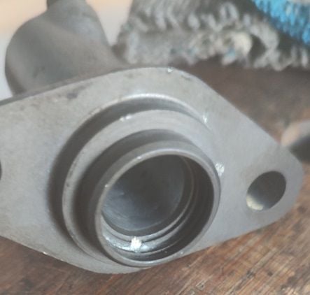
The next step was the body of the slave cylinder. Unfortunately after hours spent cleaning the thing it became apparent that corrosion damage in the bottom of the bore [where presumably the brake fluid had leaked and sat festering away as it absorbed water probably forming acids that like to break down the passive protection coating oxide film on the metal surface] had damaged the cylinder such that as it stands the unit is junk. The body from my spare slave cylinder had fared much better with no obvious signs of corrosion damage so hopefully that will be OK. A bit of research revealed that O rings like to sit in an environment with a surface roughness in the region of 5Ra to 10Ra which is equivalent to the finish created when polished with 600 grit wet and dry. So, to clean things up I stuck some 600 grit paper on a 1/4 inch drive long reach socket whose length was a bit more than the depth of the cylinder and whose diameter was a tad smaller than the inner diameter of the cylinder. I then attached the socket to my impact driver and using water I cleaned the bore of the cylinder for a few minutes and then put a spot of alloy polish on the paper and polished the inside of the cylinder a bit. The end result was nice and clean, gave it a good was/degrease with dish washer soap and called it a day. The finish felt good to the touch when using my left pinky! Slave cylinder with blocked drain hole
The above photo is the GTS slave cylinder after having been cleaned up some- note the blocked drain hole and the terminal corrosion damage in the lower bore.
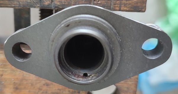
I then drilled out the drain hole on my spare slave unit with a 1.5mm bit to help prevent future blockage as per photo below .
Next step was to assemble the revamped slave cylinder from my late 90S4. I had no choice but to use the new conrod I had made locally but the new piston will be put to one side for another day [maybe] if i have problems with this setup. Shown in photo below:
I had the flange diameter and flange thickness on the conrod increased a little but otherwise a copy of the original. I will comment about piston design in a separate post shortly. I assembled the piston into the cylinder carefully adding some silicon grease and one has to ease the piston into the cylinder carefully sort of rocking the piston as it enters. once in board I inserted the conrod, the washer and then the snap ring to lock it in place.
Slave cylinder ready to install
Once the slave cylinder was mounted I then set about flushing the old fluid out using the procedure Louie sent me many years ago. It really is very easy to perform. I used about 750cc of brake fluid in the process.
As of today the system is working nicely and time will tell if the cylinder seals the brake fluid - I am not overly confident but did the best I could.
I will talk about my findings regarding piston design and O ring design shortly for anyone who may be interested in such.
Last edited by FredR; 03-30-2024 at 06:11 AM.
Reason: added "NOT" to correct context
Regarding PSD system operation- the system design is very interesting in that it is a bit like the anti lock braking system in reverse so no real surprises that the ABS computer controls this sub system. An interesting feature of the design is that under normal circumstances a small pressure is locked within the slave cylinder by a somewhat innocuous device mounted in the hydraulic line and located on the other side of the diff unit from the slave cylinder. this device releases pressure when driven by the lock solenoid valve recycling back to the reservoir but when the pressure drops to 3 barg it closes completely and traps the residual pressure. This helps ensure that the conrod is putting a small force on the clutch pack at all times even when the clutch pack has worn some. As I stated earlier the clutch pack can wear by a total of 2.5mm as measured by the clutch pack height or by 10mm as measured by conrod stroke. Thus no matter the state of the clutch pack the clutch plates should not chatter and are immediately ready for compression as per computed demand.
The special tool that checks the wear of the clutch pack is little more than a $1k dipstick. When the clutch pack is new it gives a reading of 34.5mm- which surprise surprise is the height of a correctly assembled clutch pack in new condition- it is not actually measuring that number rather it is simply a calibration point that can be used to set/check the pivot arm bolt adjustment that should already be in the factory set position anyway unless someone has dicked around with it and I would say that has to avoided- period- as it achieves nothing of value!. After assembling the system I checked the float on the pivot arm and it seemed to move about 2mm and that seemed to me to be "reasonable". Of course I knew the height of the clutch pack that came from my 90S4 transaxle diff given I measured it. If one knows the pivot bolt is correctly adjusted one can take a reading using a simple depth gauge compared to the mounting flange dimension- record such and use to check the wear by comparison in the future. Personally I could not be bothered given I have a "feel" for how the pivot arm should be and I know the clutch pack is currently in as new condition. Given I use wider than stock wheels and very grippy rubber the only time I expect to see the PSD warning light come on is on track day type events or if and when i am goofing around- not too often these days!
For some time I have wondered how the system works and now i reckon i have that fathomed out. The ABS computer is constantly scanning inputs in real time looking for a locking wheel event or detecting need for PSD system activation. The computer obviously has some kind of programmed algorithm and considers wheel traction and acceleration vectors in a 360 degree plain and if and when certain values are computed it applies a pre-determined lock up correction. The motive force to drive such comes from the pressure reservoir that operates on a simple two position control basis wherein the pump kicks in when the pressure drops to 130 barg and cuts out when it hits 180 barg [i.e. 2600 psig]. Given the system is hydraulic it is non compressible and if it was a simple system- aka a vessel under pressure- it would rapidly decompress and be uncontrollable. For this reason the pressure accumulator has a built in pressure bladder of some kind accumulator that as I recall is pressurised to about 70 barg. Then when the pressure pump charges the vessel the bladder compresses, its internal pressure increases, its internal volume decreases and thus provides a variable "working volume" at very high pressure to facilitate a rapid response. Now, considering these "1987 state of the art" computers, we know they can detect knock events and correct timing on the next firing stroke at 6500 rpms. At that engine speed it takes approx 5 millisecs for the engine to complete two revolutions so we know that the computer can achieve that kind of response time [or better].
Once the computer algorithm has computed a load demand it applies a system of very rapid pulses on a scale of zero to 20 pulses that build up the pressure in the slave cylinder up to a maximum of 60 barg and at that pressure 100% lock up is achieved and can do no more no matter what. The computer will then leave the diff locked at that point until such time as a decreasing signal is detected and then it will instruct the lock solenoid to release pressure in that same way. This is why bleeding the system correctly is so important- if any air is trapped in the system it will not work- period!
The system has no feedback control loop of any kind- it simply assumes that when the computed value is applied the system will respond as predicted/needed. Thus when the driver sees the green light come on all that tells the driver is that some kind of PSD correction has been computed and the system is attempting to apply such- whether it was successful or not probably depends on whether you hit a tree or not!
For safeguarding purposes I have to assume that the system is programmed to apply no more than 20 pulses accumulated at any given time. If the pressure in the slave cylinder comes anywhere close to where the pressure reservoir operates at I reckon something would go "twang" and most probably that would be the conrod bending under compressive load. As per my calcs the pressure in the slave cylinder [circa 60 barg/900 psig] will generate a compressive stress on the conrod of approx 30,000 psig which if correct means that any more pressure would cause the condrod to yield - thus a natural form of safeguarding albeit an undesirable consequence.
Reference to the WSM section 39 [?] regarding the PSD system advises methods as to how to check these pressures are being achieved.
If anyone happens to know anything different kindly advise such. I believe I now understand how the system actually works but...?
Wow. Just, wow, Fred. What an incredible write-up I hope I never have to go in there and replace the clutch disks, but if I do, this thread will definitely help. And, good job rebilding your slave cylinder! I think if it does leak you'll be able to quickly spot a small puddle of brake fluid on the floor where it would leak out the slave cylinder's weep-hole.
Wow. Just, wow, Fred. What an incredible write-up I hope I never have to go in there and replace the clutch disks, but if I do, this thread will definitely help. And, good job rebilding your slave cylinder! I think if it does leak you'll be able to quickly spot a small puddle of brake fluid on the floor where it would leak out the slave cylinder's weep-hole.
I put a fresh piece of Ikea cardboard box under the tranny to help detect any drops but I doubt they would be present when parked. I will check the fluid level in the PSD reservoir after a few rides. The problem was initially I thought both slave cylinders might be buggered given the piston on the 90S4 unit was well stuck and I had to drive it out quite aggressively using a small Allen key as a drift- was not sure if that had scored the inner part of the bore. That piston was not recoverable so I moved to have a piston and con rod made for me locally. The piston could still be used with the spare rings in the seal kit if needs be. However I have a revised piston design in mind and I intend to see if I can get the damaged GTS cylinder bored slightly to remove the damage and then make a piston to suit the finish bore. I now know why the designers finished the seal the way they did but will write a bit more about that in my final technical post regarding my findings about seal design shortly.
At the moment the transmission is working fine- I hope to give the PSD system a bit of a workout next weekend all being well. The only thing I could not make up my mind about was whether to use my pressure bleeder to top up the reservoir as i always manage to spill some brake fluid. In the end I chickened out, used the small bottles the fluid came in and spilt some! On the other hand I always pack an old cloth in and around the PSD unit just in case!
The only thing I could not make up my mind about was whether to use my pressure bleeder to top up the reservoir as i always manage to spill some brake fluid. In the end I chickened out, used the small bottles the fluid came in and spilt some! On the other hand I always pack an old cloth in and around the PSD unit just in case!
I use my wife's small pyrex measuring cup from the kitchen for that task.
Many moons have passed since I first saw that timely clip- notice how towards the end it talks about a response time in terms of a millisecond yet some folks say it is not "quick enough'. If that is not quick enough then what is?
As promised earlier some info on O-ring design relative to what is seen in the PSD slave cylinder.
The seal is seated in the middle groove of the three grooves in the piston. The outer and inner grooves are identical and appear to act as bearings designed to stabilise the piston as it traverses the bore. These rings are split and perform no sealing duty- they are 2mm thick and when sitting in the groove they form an outer bearing diameter of 16.3mm that sits in the 16.5mm bore. Also also aalso
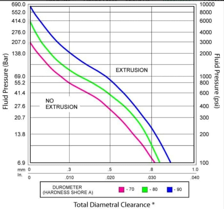
Engineering without numbers is �guessing�- plain and simple. The numbers quality control the design as it were and O rings are no different. Given I possibly needed to redesign the seal system I set about trying to establish some numerical analysis of the seal design. It took me a while to fathom out what the designers had in mind but eventually the logic clicked into place as it were. The enemy of dynamic O rings seals is extrusion that will destroy the seal quite quickly if it is overbearing. One of the first useful pieces of literature I found was a diagram that maps out acceptable performance � attached below.
This diagram shows quite clearly that the design pressure the seal can handle is controlled by the clearance between the piston and the bore and by the Shore value of the seal material. A �firmer� material [i.e. greater Shore value] will permit greater seal pressures but at some cost to seal performance at lower pressures- most O ring seals are rated at 70 Shore for best all round performance or so it seems.
The PSD piston has a diameter of 15.9mm and a bore of 16.5mm- thus a diametral clearance of 0.6mm which is a somewhat large gap in relative terms. At such clearance the seal can only handle about 18 barg as per the diagram whereas it needs to handle about 60 barg at full lock up. Initially I had no idea why they did not increase the piston bore to 16.3mm as that would have generated an allowable working pressure of 70 barg. I eventually figured that by using a sandwich type seal arrangement the idea of the outer PTFE ring is to seal up the ring space so that there is no possibility of extrusion taking place. When heated the PTFE square ring can stretch just enough to permit installation over the perimeter of the piston but �feel� told me that it would not take much error to cause the outer ring to fail due to plastic deformation.
Assuming my logic is correct and the outer ring forms in effect a closed aperture with zero diametral clearance an appropriately sized O ring can handle up to 140 barg- quite a large factor of safety and thus perhaps why only one O ring seal is needed. The central groove has a width of 2.4mm, the diameter of the groove is approx. 11.4mm. The outer PTFE square ring has a thickness of 1.0 mm and a width of 2mm and sits tight against the cylinder bore thus the diameter of the annulus on the inboard side of the outer seal is 14.5mm. The inner seal ring appears to have an inner diameter of 11mm, a thickness of 1.9mm and presumably is made from EPDM rubber that is resistant to brake fluid. This tells us that the inner ring is in effect controlling the sealing. It is under extension when fitted [that is good], the natural outer diameter of the inner seal ring when fitted is 15.2mm and thus there is compression against the outer PTFE ring. Dynamic O ring seals need compression to be in the range of 10% to 20%. By configuring the seal this way the PTFE handles the dynamic sealing against the bore and the inner O ring creates contact pressure to ensure that pressurized fluid cannot pass and avoids having a conventional O ring sliding along the cylinder wall- a very smart design I suspect!
To verify the original design I found a very neat on-line calculation utility at the Ceetak.com website. I loaded the above data & the results were interesting- nearly a perfect fit and obviously workable. See the calculation summary sheet below. Basically the data I loaded treats the design as though it was a bore of 14.5mm and piston of 14.5mm hence zero eccentric distortion. The model has two extremes of tolerance pre-programmed and tests to ensure the design will work irrespective of whether it is at the lower end of the range or the higher end.
To conclude- the stock seal works perfectly OK but if we wanted to install a single O ring type seal, this could be done but the piston diameter would have to be increased to 16.4mm and that is very tight. So if the repair works all well and good, if it fails then I know where to go next. A single O ring EPDM seal 13.0mm inner diameter and 2.0mm thickness is easily available. All three grooves would be identical and it may be better to have all three rings sealing if there is not too much resistance to movement- simply use silicon grease to lubricate the thing. If I end up with problems in due course I may well try this approach.

 03-25-2024, 03:14 PM

")


 I hope I never have to go in there and replace the clutch disks, but if I do, this thread will definitely help. And, good job rebilding your slave cylinder! I think if it does leak you'll be able to quickly spot a small puddle of brake fluid on the floor where it would leak out the slave cylinder's weep-hole.