

Problem with diff seemingly locking up
 01-22-2024 | 01:12 PM
#16
Thread Starter
Rennlist Member
Joined: Jun 2005
Posts: 9,968
Likes: 784
From: Oman
What is the torque rating? Riyobi is quality kit so I would tend to believe what they say.
Just had another look at the task at hand and maybe I can undo the half shaft bolts and lower it out of the way with the stub axle still connected- thoughts?
Just had another look at the task at hand and maybe I can undo the half shaft bolts and lower it out of the way with the stub axle still connected- thoughts?


The following users liked this post:
RennHarry (01-22-2024)
01-22-2024 | 03:29 PM
#19
Thread Starter
Rennlist Member
Joined: Jun 2005
Posts: 9,968
Likes: 784
From: Oman
Hi Phil,
It sure does and will be absolutely necessary if i have to remove the clutch pack as seems likely.
The trouble is both my other vehicles have full tanks of fuel at the moment and so does the 928 that has about 80 litres on board at the moment given I filled it just before this problem became apparent. Even my 20 litre jerry can is full just to add insult to injury.
01-24-2024 | 02:47 AM
#20
Rennlist Member
Joined: Aug 2006
Posts: 938
Likes: 35
From: Cromwell, New Zealand
Myles
01-24-2024 | 07:31 AM
#21
Thread Starter
Rennlist Member
Joined: Jun 2005
Posts: 9,968
Likes: 784
From: Oman
My query was aimed at resolving whether with the flange bolts undone and the shaft lowered [but still retained], it would generate enough access to get at the slave cylinder. Either way I will probably remove the half shaft completely, drain the fuel tank and remove that completely. Then I can drain the diff and remove the cover plate to take a look at the insides and see if there are any signs of clutch plate material fragments.
Was not feeling too clever yesterday so read up section D39 of the WSM in more detail. The amount of lock up applied is controlled by the applied pressure in the slave cylinder and it seems this is achieved by applying a specific number of release pulses on the hydraulic unit to achieve the computed degree of lock up. The break torque is plotted as a function of hydraulic pressure. The test procedure seemingly requires a special kind of torque wrench and when with the hand brake applied, the left hand hub starts to move as the wrench clicks that defines the break away torque when they coincide.
If as I suspect the clutch pack has swelled [as Bruce defined earlier in the thread], I should be able to "unlock" the diff if I release the pivot bolt used for setting the system. Needless to say I will release this in increments of 1 full turn until I detect the unit slipping at the specified torque [less than 50 ft lbs]. If this proves to be the case then I will know for sure what I am dealing with and if nothing else I can at least run the thing until I implement a solution. I will also know how many turns are required to set it back to where it current is. Anyone see a problem with this?
I also intend to remove the diff pack from my spare transaxle unit to get a feel for the removal process. This should enable me to harvest a viable clutch pack all being well given this unit had only covered some 120k km at the time I lost my late 90S4. Seems there is some spec difference in the clutch pack deployed in the GTS compared to that in the 90S4 - whether that is of any real world significance remains to be seen. Porsche generally do not change things just for the sake of it [or so I tend to think]!
01-25-2024 | 05:15 PM
#22
Thread Starter
Rennlist Member
Joined: Jun 2005
Posts: 9,968
Likes: 784
From: Oman
Today I pulled the diff unit from my spare transaxle unit quite a simple task. My intent was to remove the clutch plates and examine them to assess suitability for use in my current unit. I was expecting to see a cover plate that would slip over the taper bearing but not the case.
Although I have a WSM there is no narrative on this unit or how to assemble/disassemble it. It looks as though the taper bearing race has to be removed to get the clutch plates out. Much appreciate if anyone can confirm this.
Although I have a WSM there is no narrative on this unit or how to assemble/disassemble it. It looks as though the taper bearing race has to be removed to get the clutch plates out. Much appreciate if anyone can confirm this.
02-19-2024 | 12:55 PM
#23
Thread Starter
Rennlist Member
Joined: Jun 2005
Posts: 9,968
Likes: 784
From: Oman
After a 6 week hiatus due to visiting the UK and other issues I got round to attacking this problem head on.
The problem with the diff is exactly the scenario as described by Bruce and Sean early on in this thread- a big shout out to them for their inputs and a fine example of how this forum should work in a collaborative manner.
Before attacking the problem I read and digested all the info I could get hold of regarding the PSD system and armed with this info was able to make some interesting conclusions that I will post about in due course.
First of all i had to remove the petrol tank that had about 80 litres of fuel in it. I undid the connection at the back right hand side of the rear wheel well, dropped the hose into my 20 litre jerry can [the insulation sleeve is split following replacing the hose and can be removed]. I jumpered the fuel pump, filled the jerry can several times and then dropped the fuel tank. With that out of the way, undoing the half shaft bolts was dead easy with my impact gun- three at a time each side then rotate the shaft 180 degrees.
With the fuel tank out and the car sat on my home brew lift bars and new 6 tonne jack stands I could sit on the floor quite comfortably with my head in the fuel tank aperture. In an afternoon I emptied the fuel tank, removed it, dropped the half shaft and removed the slave cylinder. Next morning I started working the diff. I figured that if hydraulic fluid had leaked into the diff then I should see fluid come out of the overflow- removed the fill plug and sure enough somewhere in the region of 50cm3 to 100cm3 appeared and that is about the same amount that the PSD reservoir lost- pretty conclusive I think. Interestingly the fluid that came out of the overflow was as clean as a whistle. I then drained the two litres of oil from the sump plug and that was very black indeed- surprising considering I replaced it two years ago.
Getting the diff back cover off was straight forward. 12 x 8mm bolts but why on earth did they fit torx bolts on the lower three fasteners that hold that alloy protective plate? Those things are not going back on. I then noticed something interesting- the rear cover on my 90S4 diff unit is different to that on the GTS. I was sure the diff held three litres but on the GTS it only took two liters. Turns out they modified the back cover for the GTS version- the castings have two bosses built into them but the GTS uses the lower boss and hence the two litres capacity compared to the three litres of the S4 version. Any opinions as to why this is?
Getting the bearing covers off took some time and patience- I used a 10 inch socket extension as a drift and using light force pressed against one of those cast in flashes on the housing to slowly and safely drive the cover out- this thing has to be a tight working fit given it purpose. Eventually both came out the passenger side being easier than the driver's side but it was not at all easy. Everything inside both housing was as clean as a whistle- just a pile of oily gunge on the outside..
Upon removing the diff unit I set about removing the crown wheel so as to gain access to the clutch basket. The locking tabs securing the nuts are probably not reusable - i suppose I could anneal them but...? The nuts are an oddball size at 20mm and had to purchase an impact socket for that size. My impact wrench made light work of removing the 12 bolts.
After removing the crown wheel I removed the clutch basket cover plate that is held by two small counter sunk screws on the under side. The cover plate came off easily and it then became apparent what the issue issue was as the clutch pack had what appeared to be 3mm additional height compared to the space available in the basket. I removed the clutch pack and it transpired that 6 of the friction plates had delaminated on one side- two of them on both sides.
The plain plates all measured 1.5mm thick except one that measured 2.1mm. The friction plates measured in the range 3.1mm to 3.5mm. As I measured them today the total thickness of the plate pack was 38.1mm whereas the depth available in the basket was measured as 34.1mm. Separating the plates and measuring the plate thickness individually suggested a thickness of 36.4 so clearly the oil layer accounts for the difference.
Lockup is achieved by compressing the plate pack just like any other multi plate wet clutch setup so with the help of friend I measured the travel range of the compression pistons and that turned out to be 3.0mm - given that is enough to take the clutch pack from zero percent lockup to 100 percent lock that clearly demonstrates why my diff was behaving like a solid axle.
Just as interesting, the travel on the engaging mount is 12mm - a reduction ratio of 4:1 so that suggests that whatever force is applied by the slave cylinder it is multiplied by a factor of 4 less its mechanical efficiency that will be in the high 90's I suspect. The internal diameter of the hydraulic cylinder is 16.0mm and as I could determine, the PSD unit applies a pressure of 60 barg to the slave unit. The cross sectional area is 0.311 sq inches and the maximum thrust developed in the cylinder will be 270 lbF or 123 KgF. So in round terms the force compressing the clutch pack will be 0.5 tonnes.
As for the slave cylinder that was a basket case. Upon removing the two mounting bolts and pulling it back slightly it was clear that the conrod was corroded, it was seized in the cup that presses against the actuating arm and the slave cylinder piston was seized in the barrel of the cylinder. There was some crappy looking gunge in the annulus between the conrod and the bellows and when I jerked the cylinder to pull the conrod out of its seat there was little left of the bellows. It also looked as though the gunge had blocked the tiny weep hole in the base of the slave cylinder mounting flange.
I then moved to dismantle the slave cylinder. The piston was well and truly seized - I left some WD40 in the barrel overnight to seep in and the following day I managed to drive the piston out using a 1.5mm diameter drift [a drill bit] inserted through the hole at the base of the cylinder that allows hydraulic fluid into the cylinder. With the piston removed it was apparent that there was serious corrosion damage on the cylinder bore and that thing is toast as it stands. I think it can be repaired but fortunately i have a spare cylinder from my spare 90S4 transaxle unit that seems OK albeit that had some issues as well.
The piston that came out of the GTS slave cylinder was in surprisingly reasonable condition and is suitable for re-use. The piston has three O rings- the outer two were cracked- all three had seemingly hardened and presumably would have been about as much use as a chocolate fireguard! The centre ring is oddball in that underneath the O ring sits another smaller O ring. i do not understand why the designers would have done this. I have designed and had made locally a new piston and conrod. Now i have to decide whether to fit them or keep them as spares. As I retrieved the piston another concern raised its ugly head. The rings being blue suggests they are made of fluoro-silicon rubber [FVMQ]. As I am aware this is not suitable for brake fluid service- invariably the rubber of choice for this service is EPDM. I need to look into this a bit more.
Hopefully spare parts will arrive in a week or so.
I hope folks who own PSD equipped models are paying attention to all this. For those who have not done so or have no idea if it has been done, simply changing out the hydraulic brake fluid is clearly not enough. I would say that once every 10 years or so one needs to remove the slave cylinder, replace the seals [and anything else that looks dodgy] and replace the bellows. I am also thinking of opening out the weepage hole a bit.
I will shortly post some pics and more dialogue about the clutch plates to follow in another post.
The following 3 users liked this post by FredR:
02-19-2024 | 02:18 PM
#24
Rennlist Member
Joined: Oct 2004
Posts: 2,905
Likes: 315
From: K-town, Germany
Hi Fred - I think you'll find this thread by MrLexse very informative. https://rennlist.com/forums/928-foru...options-4.html
Roger now sells the seal kit: https://928srus.com/products/psd-sla...1a787308&_ss=r
Coincidently, I had one MrLexes kits from 10+ years ago and tried installing it last week, but unfortunately the middle ring snapped during installation. In the end, I didn't want to wait for shipping and risk breaking another one, so I left the local Porsche dealer 500 euro poorer and bought a new slave cylinder.
I 100% agree with your assessment: periodically remove the slave cylinder and check the rubber baffle and check the condition of the slave cylinder itself. And for sure, keep the weep-hole on the bottom of the cylinder cleaned-out so it will be easy to spot drips in case the cylinder leaks.
02-19-2024 | 03:28 PM
#25
Thread Starter
Rennlist Member
Joined: Jun 2005
Posts: 9,968
Likes: 784
From: Oman
Hi Fred - I think you'll find this thread by MrLexse very informative. https://rennlist.com/forums/928-foru...options-4.html
Roger now sells the seal kit: https://928srus.com/products/psd-sla...1a787308&_ss=r
Coincidently, I had one MrLexes kits from 10+ years ago and tried installing it last week, but unfortunately the middle ring snapped during installation. In the end, I didn't want to wait for shipping and risk breaking another one, so I left the local Porsche dealer 500 euro poorer and bought a new slave cylinder.
I 100% agree with your assessment: periodically remove the slave cylinder and check the rubber baffle and check the condition of the slave cylinder itself. And for sure, keep the weep-hole on the bottom of the cylinder cleaned-out so it will be easy to spot drips in case the cylinder leaks.
Roger now sells the seal kit: https://928srus.com/products/psd-sla...1a787308&_ss=r
Coincidently, I had one MrLexes kits from 10+ years ago and tried installing it last week, but unfortunately the middle ring snapped during installation. In the end, I didn't want to wait for shipping and risk breaking another one, so I left the local Porsche dealer 500 euro poorer and bought a new slave cylinder.
I 100% agree with your assessment: periodically remove the slave cylinder and check the rubber baffle and check the condition of the slave cylinder itself. And for sure, keep the weep-hole on the bottom of the cylinder cleaned-out so it will be easy to spot drips in case the cylinder leaks.
Last edited by FredR; 02-19-2024 at 04:11 PM.
02-20-2024 | 03:36 AM
#26
Thread Starter
Rennlist Member
Joined: Jun 2005
Posts: 9,968
Likes: 784
From: Oman
Hi Fred - I think you'll find this thread by MrLexse very informative. https://rennlist.com/forums/928-foru...options-4.html
Coincidently, I had one MrLexes kits from 10+ years ago and tried installing it last week, but unfortunately the middle ring snapped during installation. In the end, I didn't want to wait for shipping and risk breaking another one, so I left the local Porsche dealer 500 euro poorer and bought a new slave cylinder.
The thread was an interesting read and I am surprised I did not pick up on that at the time
You could do a lot worse than purchase a new slave cylinder- I am currently on the fence on that one.
Last edited by FredR; 02-20-2024 at 04:03 AM.
02-20-2024 | 02:25 PM
#27
Thread Starter
Rennlist Member
Joined: Jun 2005
Posts: 9,968
Likes: 784
From: Oman
So today I worked on the clutch packs of both units.
First of all I worked on the clutch pack pulled from the GTS. I reported earlier that the pack thickness was nearly 4mm greater than the space available to fit it in and that the stroke needed to lock the pack 100% is 3mm. I cleaned, inspected and measured the thickness of each plate writing down the results for each plate. The plain plates were typically 1.5mm and the friction plates over 3mm. Something struck me as not being quite right and then it dawned on me what it was. PET says there should be 10 friction plates and 9 plain plates but in fact there were only 8 friction plates and 7 plain plates. I acquired this vehicle in early 2006 and no one has touched the diff in that time so what the hell has been going on? I need to take a look at the service history at the main dealers. I reported earlier that I had a feeling something has been going for quite some time but maybe it even pre-dates my ownership?
Anyway I then worked on the diff out of my spare transaxle - my aspiration being that I can buy some life with the clutch pack from the 90S4 diff unit. This unit had 10 friction plates and 9 plain plates as it should. Now if one looks at PET it says that the unit has 5 plates of a specific part number and 5 plates of a different part number but it does not say what the difference is. As I catalogued the data it became apparent that there was a pattern wherein one friction plate of 1.8mm thickness was followed by a plain plate and then a plate of 2.4mm thickness. The thicker plates had like a narrow groove and then material at the base of the groove making me wonder if that was a visual indicator for wear pattern . When fitted into the clutch basket the plates appeared to fill the available space perfectly. It is not logical to think the narrower plates are that way due to wear and the WSM says that the $1k dipstick used to measure wear shows a deficit of 10mm when the plates are worn. Now if you remember in my earlier post I observed that the lever arm has a velocity ratio of 4 to 1 so 10mm on the push arm equates to 2.5mm of linear wear pattern. Given there were no obvious signs of wear as in the clutch plates not filling the basket I am pleased to say I feel optimistic I have something to work with here.
All this makes me think that the adjusting bolt is something you simply wind in until it is finger tight with no obvious slack and then lock it up. When I reassemble the unit I will check the position I found it in to see whether this holds and will report back in due course. Should be easy to tell with the back cover off.
Will try to post some pics tomorrow.
The following users liked this post:
RennHarry (02-21-2024)
02-21-2024 | 06:26 PM
#29
Thread Starter
Rennlist Member
Joined: Jun 2005
Posts: 9,968
Likes: 784
From: Oman
That is what I found - the only info I had to go on was PET and that states the S4 and the GTS have the same plate config and this made me wonder if in its earlier days someone had dicked around with the basket. The actuation mechanism is such that 12mm of slave stroke results in a compressive movement for the 4 pistons of 3mm - i.e. a velocity ratio of 4:1 thus 3mm of piston stoke will lock the diff 100%- the pack had swollen such that when opened, the plate sat nearly 4mm higher than the space available- exactly what Bruce and yourself advised initially.
That being said my S4 pack fits nicely and seems to be in good condition. The PET entry shows two different friction plates but no data about thickness or whatever the difference may be. PET shows these plates installed as 5 of one type and then 5 of the other type whereas the construct in my S4 diff showed the plates alternating- their respective friction thickness being 1.8mm and 2.4mm respectively. I have assembly the GTS diff with these plates installed.
The body of the GTS slave cylinder is goosed- it seems the fugitive brake fluid absorbs water and that causes the stuff to acidise - unfortunately aluminium loses its passive coating in acidic conditions and the lower part of the barrel is corroded and thus no use as it stands - now I am trying thinking of a procedure to recover the barrel. The piston will be serviceable with new seals. The S4 slave cylinder seems OK barrel wise. I also had a new piston and conrod made for me. I may use this or the stock item. I am trying to see if I can design a better seal system but given these things generally last 20 years plus it is not something one can describe as being a failure. As I said earlier preemptively change them out every 10 or 15 years and there will be no problems.
Again many thanks for the support.

The piston- not as bad as it first looks

The steel bush of the bellows was well and truly stuck to the piston. Very little sign of the rubber bellows
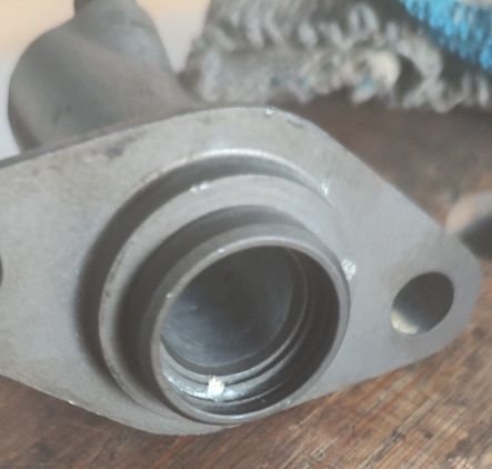
The drain hole was blocked with aluminium oxide. One can just about see the surface corrosion damage on the lower surfaces of the barrel. The piston was seized about half way along the barrel.
Last edited by FredR; 02-21-2024 at 06:28 PM.
03-12-2024 | 08:49 AM
#30
Thread Starter
Rennlist Member
Joined: Jun 2005
Posts: 9,968
Likes: 784
From: Oman
After a couple of weeks travelling I am now ready to start assembly.
The clutch will be the one from my 90S4- it has been sat in its housing for nigh on 20 years but looks in good nick. Looking for opinions on preparation- some say soak the plates in the medium it will be exposed to for an hour or so, some say lubricate the plain plates so there is something to slip against- thoughts?
For the bearing carriers I have new shaft seals to install. I think it is better to install them before mounting the carriers using a press but then maybe there is a danger of mechanical damage during installation of the diff? - thoughts please.