When you click on links to various merchants on this site and make a purchase, this can result in this site earning a commission. Affiliate programs and affiliations include, but are not limited to, the eBay Partner Network.
Michael, I think your leak test (and other checks) are valid, as far as they go. By blocking the intake at the MAF and pressurizing the plenum, you are checking for leaks from anywhere in the intake system to atmosphere-- all the hoses under the intake, etc. But you are not testing any of the normal idle-air paths, those are all inside your "test chamber". The idle speed is high because the engine is getting too much air through or around the throttle plate, with the throttle closed.
There are three paths for idle air:
(1) The throttle plate obviously, which is held slightly open by the mechanical idle-stop. You backed that off without change, so that's not it.
(2) The ISV circuit, a valve that bypasses the throttle plate and is used by the LH to control idle speed. If idle speed is low, the LH opens the ISV and lets more air bypass the throttle. Those hoses are under the intake, and often soften and split-- but that creates a leak to atmosphere which shows on a smoke test.
3) The brake venturi, the "Y" connector and the hose loop shown in the photo where you connected the smoke. The end you can't see (to the right in the photo) connects to a Y-fitting in the rubber boot securing the MAF (along with the ISV), the other end goes to the side of the intake plenum. This loop does two things: provides another air bypass around the throttle plate for idle air, and increases the vacuum to the brake booster via a venturi.
So one of those three paths is supplying too much air. You've pretty much eliminated the throttle plate and the ISV loop, so disconnect the venturi and give it a good look. Intake vacuum pulls air through a small venturi from the MAF side of the throttle body (i.e. atmos pressure), increasing the vacuum on the booster connection. The hole through that venturi should be 4mm, check it with a 5/32" drill bit--- should barely fit. One way to solve a too-low idle problem (caused by someone messing with the idle-stop screw) is to drill out the brake venturi to compensate. Then when the original problem gets fixed, you are left with too large a flow through the venturi, and a high idle. If in doubt, swap it for another. Blocking the booster connection doesn't do anything, that's a dead-end anyway. If you block or pinch-off the hose connection to the plenum then the engine should die, it needs that additional idle air. And opening that plenum connection to atmosphere should kill it also, due to a too-lean mixture from the large unmetered air leak.
Thanks, Jim, I'll take a look when I do another round of testing this afternoon. I have an extra Venturi from my S4 moto I can compare the two.
I did take the car for a drive and it drives fine, but coming back to idle is problematic. The idling got progressively worse as I was driving it. Here is a short video of it as I idled outside my driveway. No input from me. It seems like it's worse now.
How easy did the injectors go back in? Were they new o-rings? Could be air getting past there?
I had that on my first intake job, o-rings were slightly too small after getting rid of the intake coating and painting it. It would run but really not as good as yours though. New slightly larger o-rings cured that on mine.
How easy did the injectors go back in? Were they new o-rings? Could be air getting past there?
I had that on my first intake job, o-rings were slightly too small after getting rid of the intake coating and painting it. It would run but really not as well as yours though. New slightly larger o-rings cured that on mine.
Tom:
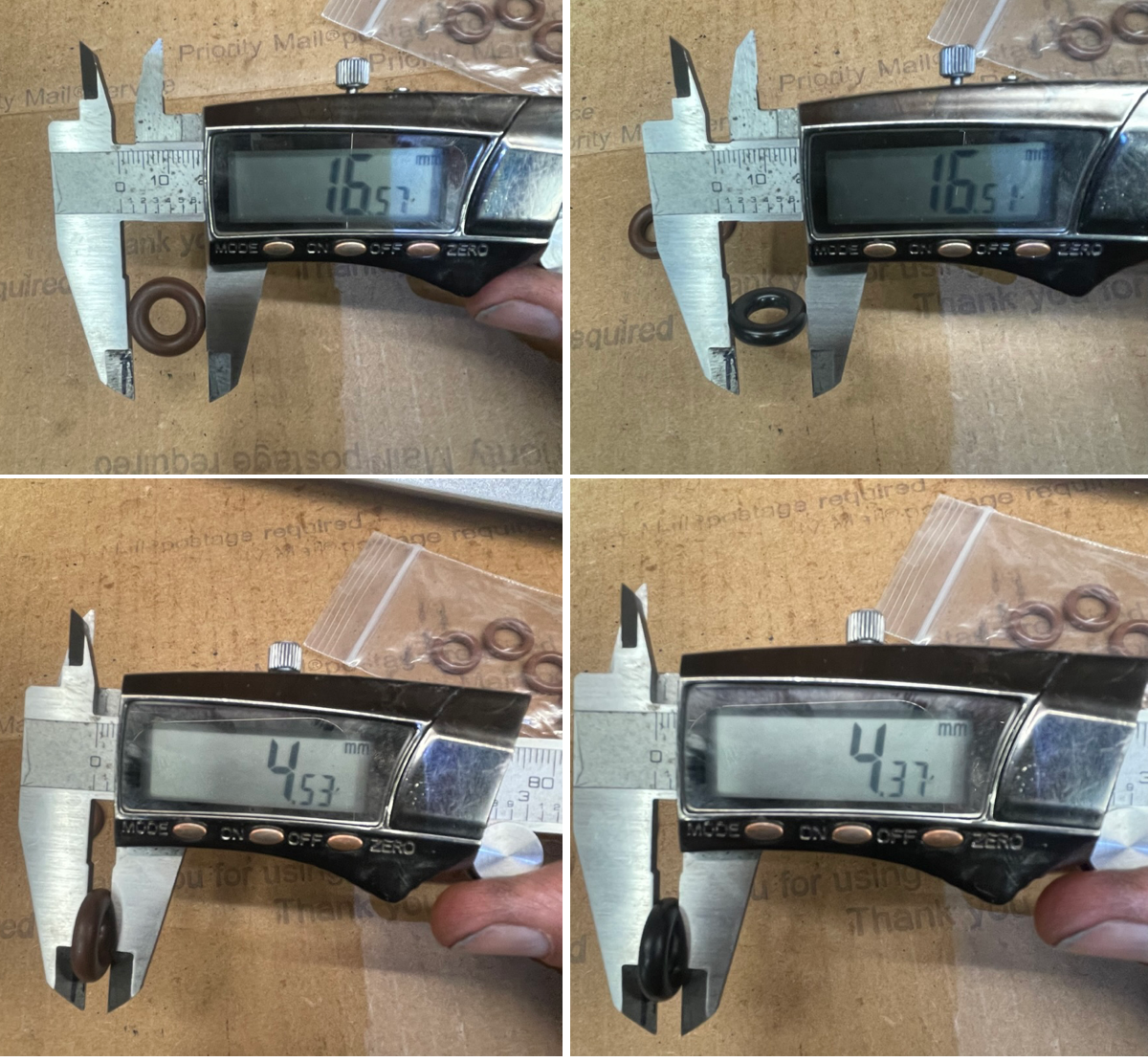
The new injectors came with the 16.5mm oversized 0-rings specific to the 928 manifold. These 0-rings are the same size as the Porsche-specific "Brown" O-rings that folks discuss as being unique and specific. The injectors fit very tightly in the ports and the only way to get them to seat is by using the nuts on the studs.
Last edited by Michael Benno; 04-03-2023 at 10:12 PM.
so disconnect the venturi and give it a good look. Intake vacuum pulls air through a small venturi from the MAF side of the throttle body (i.e. atmos pressure), increasing the vacuum on the booster connection. The hole through that venturi should be 4mm, check it with a 5/32" drill bit--- should barely fit.
I pulled the venturi and compared it to a spare one. The internal diameter for both is about 4mm. I checked. them with the 5/32" bit. So that is one more thing off the list.
Last edited by Michael Benno; 04-03-2023 at 09:58 PM.
Crankcase ventilation plumbed like a '92, a '93, or my way?
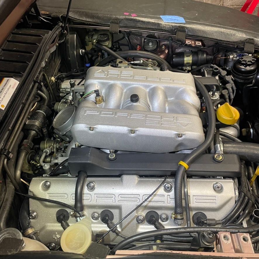
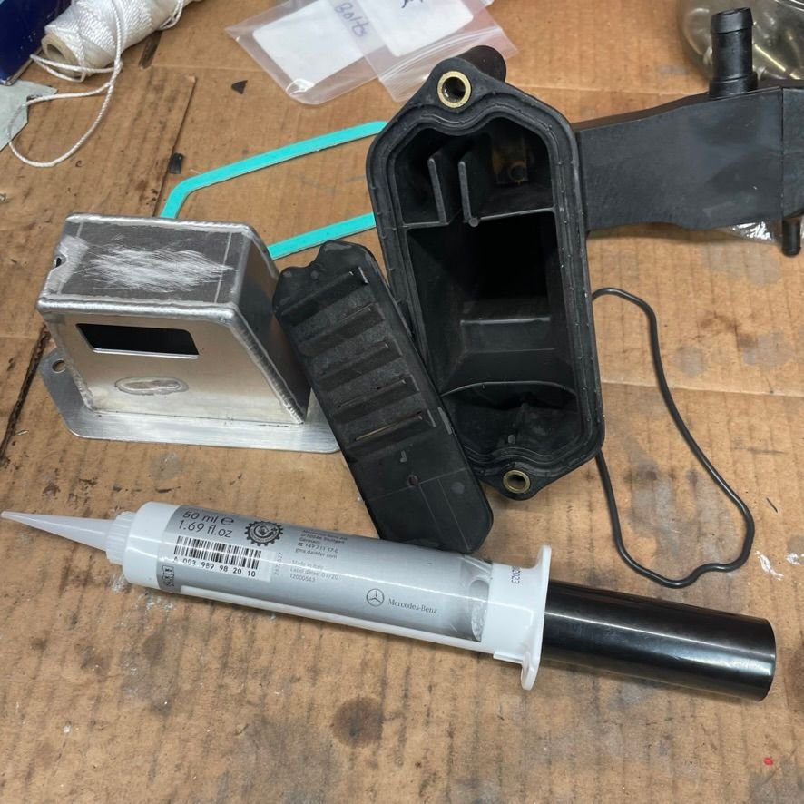
Hi Greg, the crankcase ventilation is set up as the version used in 1993+ models, plus a Precision Motorwerks Oil Filler Neck (OFN) baffle. The OEM oil baffle that is installed in the right rear valve cover has been deleted. Also using the crossover tube between valve covers.
The right rear elbow on this valve cover has a restrictor in it. I realize the factory changed this to be full bore for 93+ systems. Im hoping this is not a significant factor since I am dealing with too much air not a restriction issue,
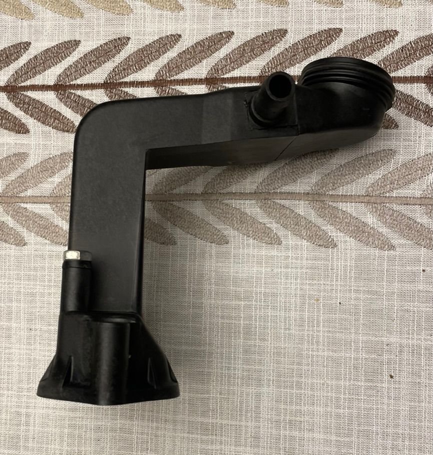
This is is the OFN used with the port on the top being plumed into the intake boot using the OEM hose for 1993+ MY. The manual notes the orifice pictured should be 5mm.
I am using a baffle under the OFN as was previously installed, I didnt use the green gasket in the background I used the Locktite 5970 product to seal it to the block.
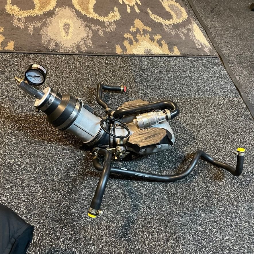
Here you can see the breather hoses mocked up and pressure tested before installation
Last edited by Michael Benno; 04-03-2023 at 10:01 PM.
It's obvious, looking at your throttle body pictures, that it is not properly centered and will be leaking excessive air.
I'm not about to give any of the "haters" here, any clues on how I know this, from just looking at your picture, or how to fix it, but you know my phone numbers and know you can call.
The left screw is not in the center but north and so you have in the south west the gap. You have good eyes Greg and the routine to sort a can of worms on every car in the shop.
Well done!
I know this situation too good, like Michael, I didn‘t see the forest because there are so much trees!
Leaving the car alone and start fresh a few days later helps often too.
To add to what Greg said about the TB plate not being centered,
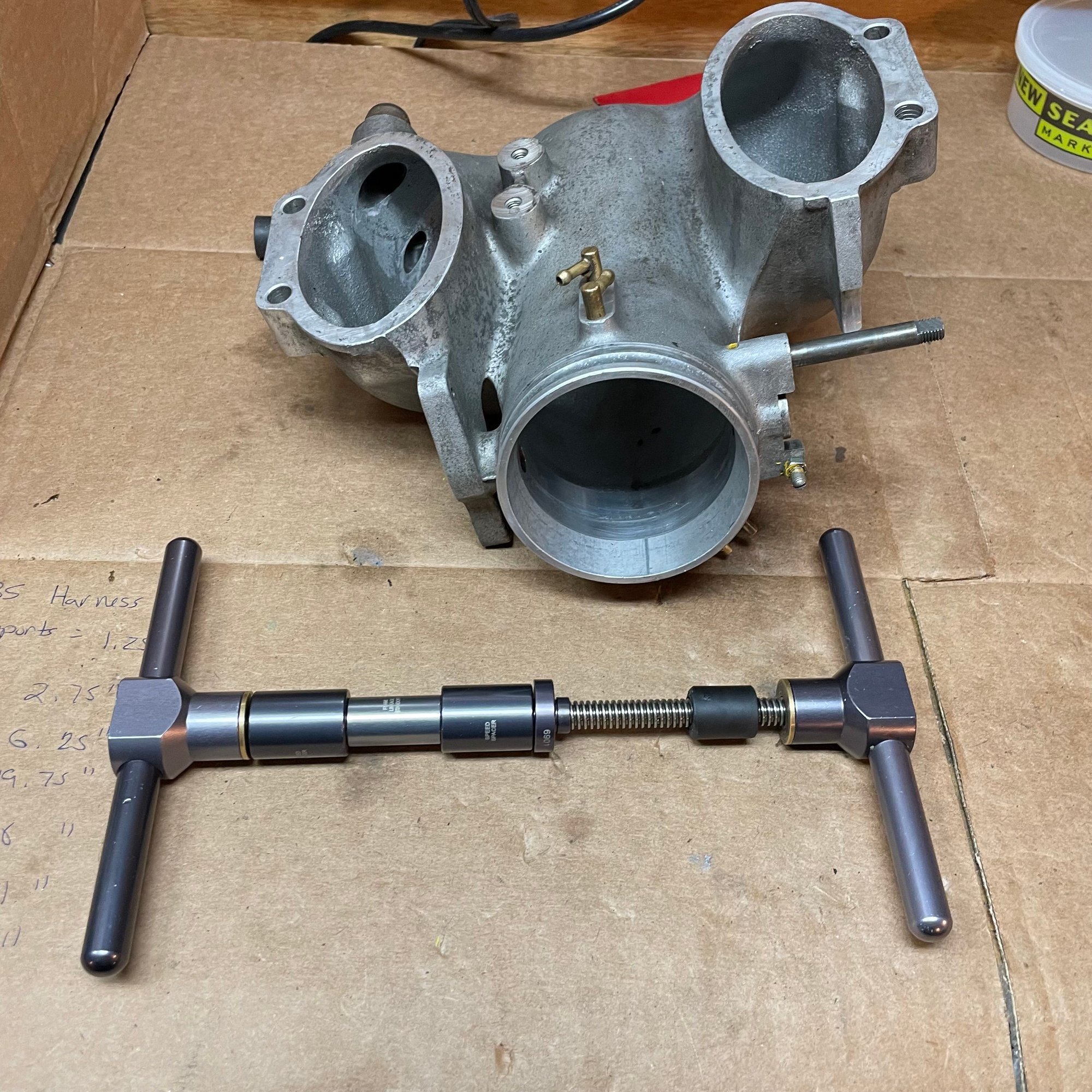
how did you install the new shaft sealed bearings?
frozen bearings with a heated housing?
ON Reassembly ,The throttle plate screws should be left loose and the plate held horizontal while gently opening and closing the the plate ,
so it can find its home>
The plate / shaft should line up with the two stamp marks left from its original position.
That said if you used excessive force to install the bearings,
then you could have deformed the housing thus,
]the plate will find a new home thats not where it was .
Sadly you loosened the shaft stop screw, that was the starting point for setting the plate.
NOTE the 2 punch marks in the plate,
these should both be close to the shaft, your picture shows them to not be equal.
To fix this plate alignment,
loosen the plate screws then then follow the instructions to see if the plate will center itself.
THEN
What color O ring are on the outlet tip of the injectors.
You should note that the only O ring that fits the S4 injector and the intake is that orange/ tan version.
I have never seen any black O rings that have the same dimension as the originals since they are an off size,
usually you can get the OD correct but then the ID is loose the O ring will let air pass around the ID,
NOTE this can occur after the intake has gotten to operating temperature then the O ring bores will expand,
this can cause a leak
Note any other O ring that you fit will not have the tight fitting that the factory orange tan O rings have for the Inner diameter
Note the injector bores on the intake must also be powder coated as this is part of the sealing for the injectors use DC 111 on the O rings
Also make sure you have replaced the two plastic junctions that go into the MAF boot as well as the MAF boot
The test I suggested in post 13 is intended to prove that excessive air is passing through the throttle butterfly. Given that the engine is in principle [but not 100%] a positive displacement machine, it stands to reason that if it is idling at 1100 rpms it must be moving nearly twice the airflow than it should at 675 rpms. In your earlier reported tests you stated that AFR's appeared to be OK so that suggests that the excess air is metered and not being sucked in through a leak and the smoke test was negative.
The metered air flowing through the venturi is a fixed amount. The air flowing through the ISV is modulating [i.e. a controlled response] and the system is designed such that it control air flow to keep the idle speed constant but if too much air passes through the main throttle butterfly then all bets are off.
The ISV is designed such that when there is no control signal being applied there is an opening sized to support a warm idle with no ac running and in my experience it works quite well once the motor is warmed up. If you run with the control signal disconnected this feature will kick in and you will still see a high idle speed. Switch on the ac and you should see the rpms drop but not die in your current state.
As I understand the butterfly adjustment screw is factory set to allow an optimal contribution of air flow through the buttterfly to support that passing through the venturi and the idle stabiliser valve. If this screw is backed out and the idle is still running high that would confirm that the butterfly is not sealing to the extent required.
If you had access to ST2 you would see the ISV signal driving to minimum as it tries in vain to control the engine speed.
Good morning everyone, thanks for all the great suggestions and positive feedback. I am so appreciative for all your guidance and suggestions.
As several of you pointed out the throttle plate is visually miss-aligned. centering such that it has a tighter fit. @Greg Brown was kind enough to walk me through the proper centering and adjustment procedure of the throttle plan and setting of the stop screw. I will need to remove the again so I can get to the parts. I'll follow up once I have it all disassembled.
Fred, your understanding of the relationship of the IVS operating range and the throttle plate position is the same as Greg explained to me last night. My first objective is to get it all apart and work on getting it centered and tight and then make some small adjustments to the screw.
Stan, thanks as always for your helpful notes. Let me try and address your questions:
Originally Posted by Mrmerlin
To add to what Greg said about the TB plate not being centered,
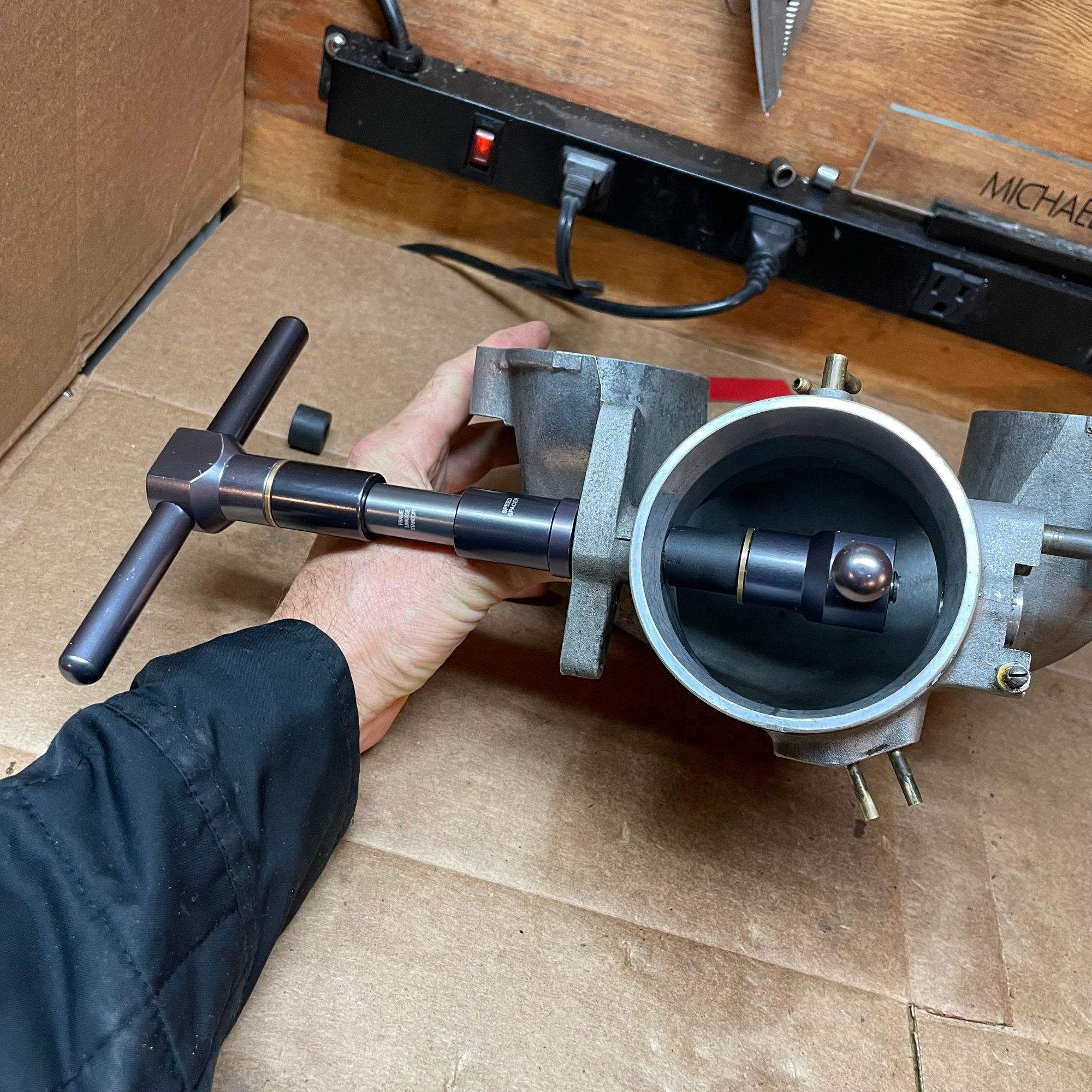
how did you install the new shaft sealed bearings? frozen bearings with a heated housing? MB: I used a small handheld bearing press (used for bicycles) with appropriate sized shims to match the bearing and opening on the housing. I pressed in each bearing separately to prevent ovalizing the opening. In the photos below you can see a black nylon bushing I beveled to match the inner circumference of the throttle to apply force without marring the surface. The bearings went in smoothly without abnormal force (I have quite a bit of experience pressing bearings into precision hubs and I developed a sense for normal vs excessive force)
.
ON Reassembly ,The throttle plate screws should be left loose and the plate held horizontal while gently opening and closing the the plate, so it can find its home The plate / shaft should line up with the two stamp marks left from its original position. NOTE the 2 punch marks in the plate, these should both be close to the shaft, your picture shows them to not be equal. To fix this plate alignment, loosen the plate screws then then follow the instructions to see if the plate will center itself. MB: Check, this was also the guidance from Greg. I'll follow this when I re-assemble
Sadly you loosened the shaft stop screw, that was the starting point for setting the plate. MB: Sad but true, I'll need to re-adjust
What color O ring are on the outlet tip of the injectors. You should note that the only O ring that fits the S4 injector and the intake is that orange/ tan version. I have never seen any black O rings that have the same dimension as the originals since they are an off size,
usually you can get the OD correct but then the ID is loose the O ring will let air pass around the ID. NOTE this can occur after the intake has gotten to operating temperature then the O ring bores will expand,
this can cause a leak. Note any other O ring that you fit will not have the tight fitting that the factory orange tan O rings have for the Inner diameter MB: The O-rings supplied with the injectors from FivoO Motorsports are 16.5mm OD and are called out specifically for the 928 in their specification. They measure the same size as the Brown/Orange O-rings I purchased new last summer. The block are a very tight fit even with the grease supplied with the injectors. I have used these seals on a previous 928 and have not seen issues with fitment after warmup. However, I can swap the O-rings with the OEM O-rings I have on hand. I'll make sure I smoke test the injector seals when it;s running to test for vacuum leaks. Good suggestion thanks!
Note the injector bores on the intake must also be powder coated as this is part of the sealing for the injectors use DC 111 on the O rings
Also make sure you have replaced the two plastic junctions that go into the MAF boot as well as the MAF boot
MB: Yes these are new. I pressure and vacuum tested the entire lower intake plenum and hose assembly prior to installation and no leaks were found.
Last edited by Michael Benno; 04-03-2023 at 10:17 PM.

 04-01-2023, 04:25 PM