When you click on links to various merchants on this site and make a purchase, this can result in this site earning a commission. Affiliate programs and affiliations include, but are not limited to, the eBay Partner Network.
i know of two people using it in their 928s. So far, about 5 years in no issues.
Jeff,
If this stuff works as advertised [and the evidence is mounting that it does]- it will stop all the corrosion issues seen in our cylinder heads given there is a very clear and obvious cascading sequence of interlinking events that I have reported on previously. The Evans Waterless Coolant is something seemingly very similar but I have even less experience of that. I am pretty sure they are both the same product [propylene glycol] with some kind of surfactant added that in effect reduces the effective viscosity of the coolant in much the same way as additives influence multi grade engine oils. If these coolants when modified have simlar transport properties as water then problem solved.
However, I came across this link pertaining to the Evans Waterless Coolant and that reported unwelcome properties I might have expected to see. No idea what the Norosion item is but will take a look. Clearly they had an axe to grind so not sure I buy into all they say.
Hi,
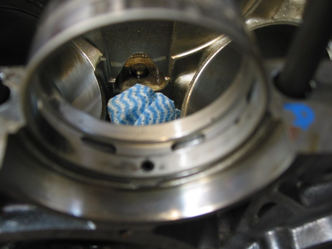
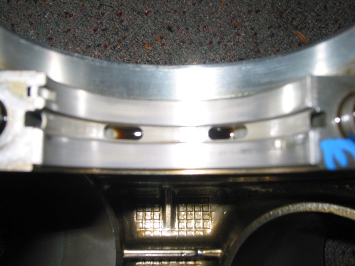
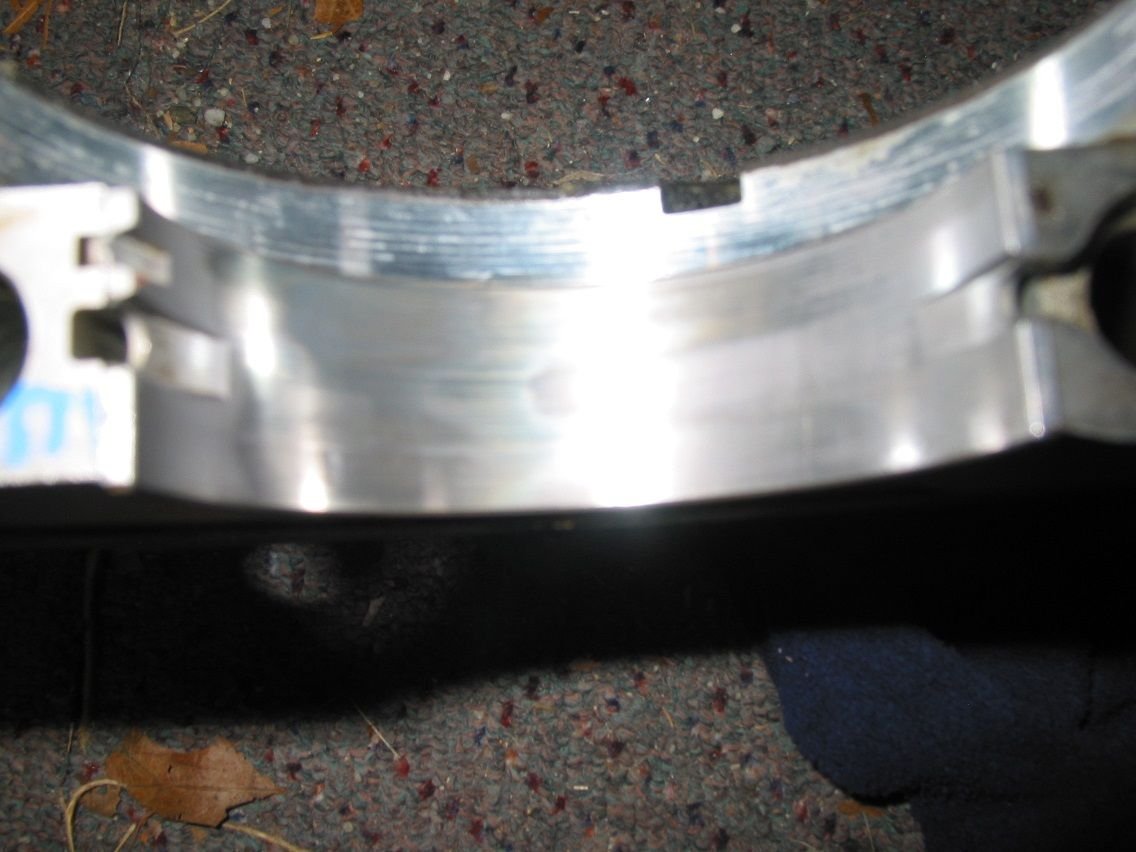
removed the lower cradle and crankshaft today.
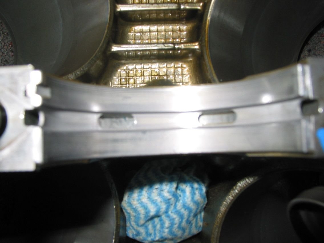
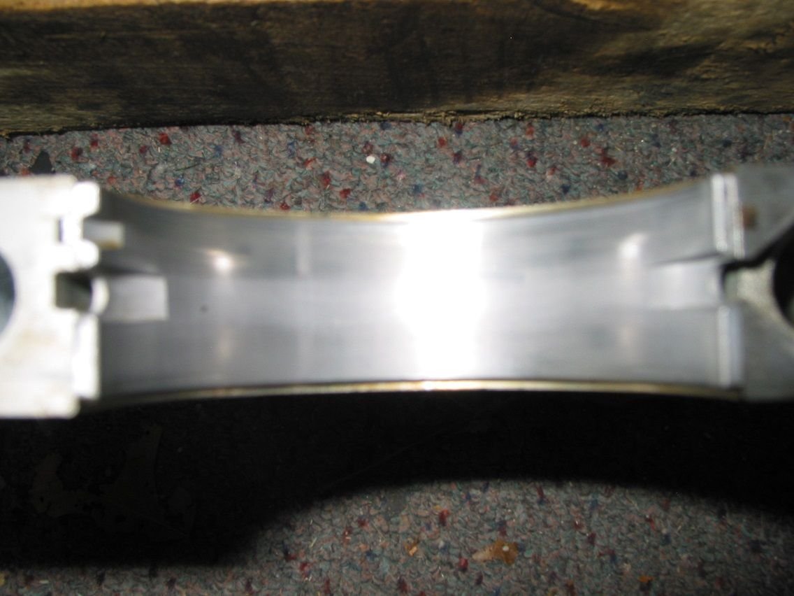
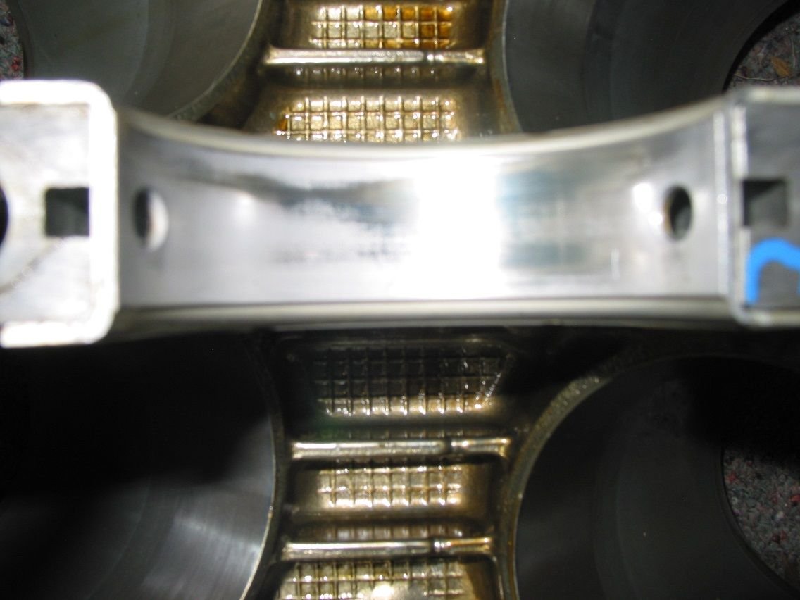
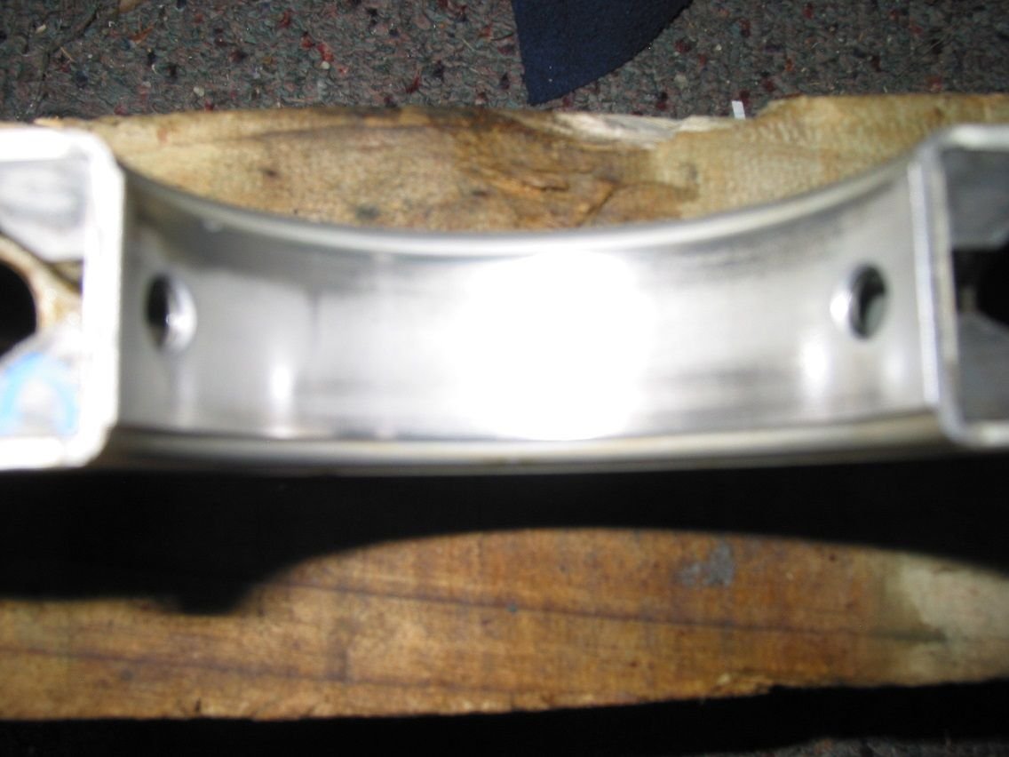
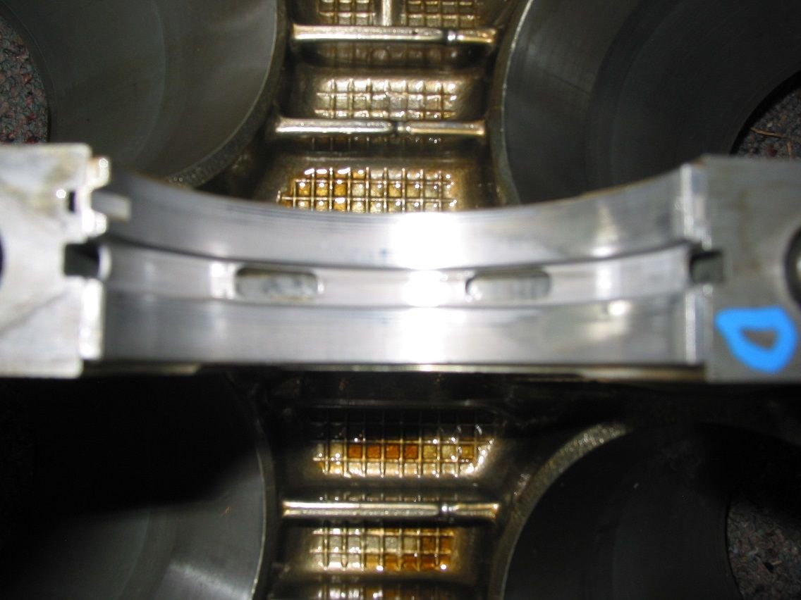
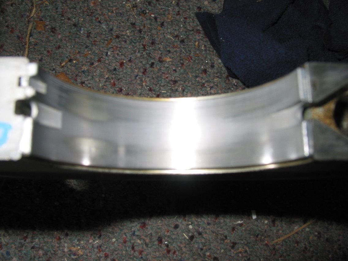
Some 'interesting' wear on some of the bearings. Comments welcome.
From front to back (sorry about the photo's - old camera technology & less than competent user.)
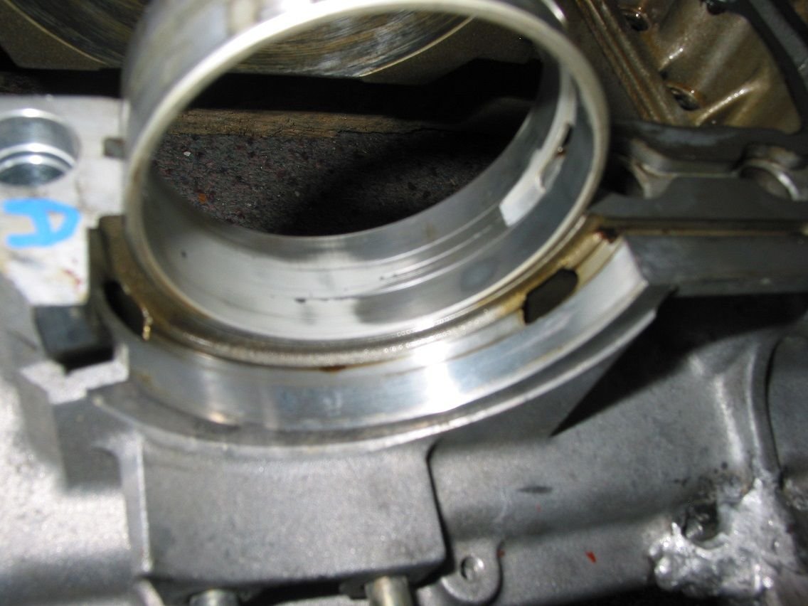
Front (A) block Front (A) cradle B block B cradle Thrust (C) clock Thrust (C) cradle D block D cradle Rear (E) block Rear (E) cradle Thrust forward facing face
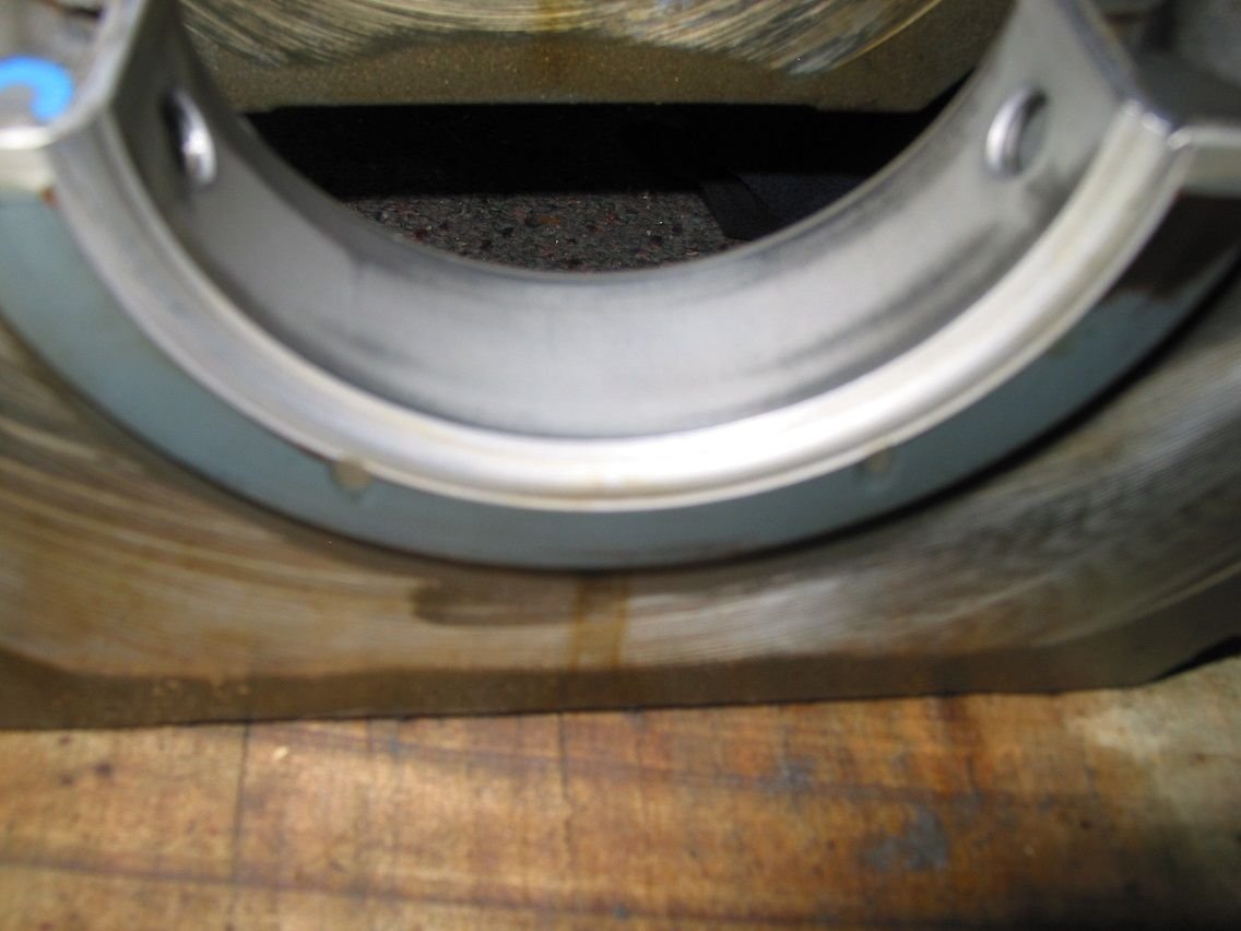
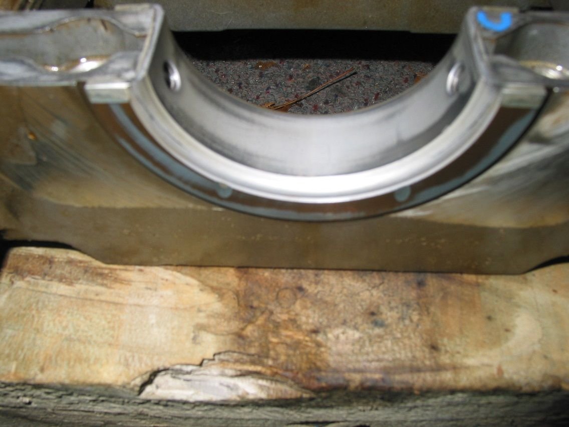
End play before removal was 0.16mm which hasn't changed since my first measurement in 2006. Thrust rear facing face
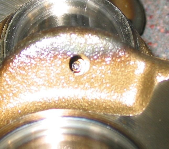
Is it necessary to remove these plus to clean out the oil passages? Are thay able to be unscrewed (looks like an allen head grub screw) or do they need drilled out & re-threaded? Crank plug
Also, a couple of questions:
One part of the WM says to only use loctite 574 (pg 13-7) whereas another part says to use 573 (pg 13-10). I presume 574 is correct from what I have read elsewhere?
The WM shows a tightening sequence for the M10 & M12 nuts on the cradle but ignores the M8 bolts around the outside of these. It looks to me that these bolts also contribute to the sealing of the oiling passages. Do they have the same time constraints as the larger nuts (10 minutes according to the WM) or can they be tightened 'at ones leisure'? If not, do they get tightened first, last or somewhere in the middle? Is sequence important?
The WM states that the M10 & M12 nuts have 'plastic threads' and are one-time use only. Does this apply to the two located outside of the crankcase as these didn't appear to have the plastic threads?
Do the M8 bolts need to be installed with any loctite. I didn't detect any when undoing them but would like to be sure.
Note to others:
I found the M8 by 30mm pan head screws (90011900402) for the starter bracket were impossible to remove with the 6mm allen key socket I had (even though it is a high quality one) and I had to resort to 'alternative' methods. Beware.
Spent some time today cleaning the crankshaft. I did not trust anyone to remove the plugs and then drill, tap and screw new ones in.
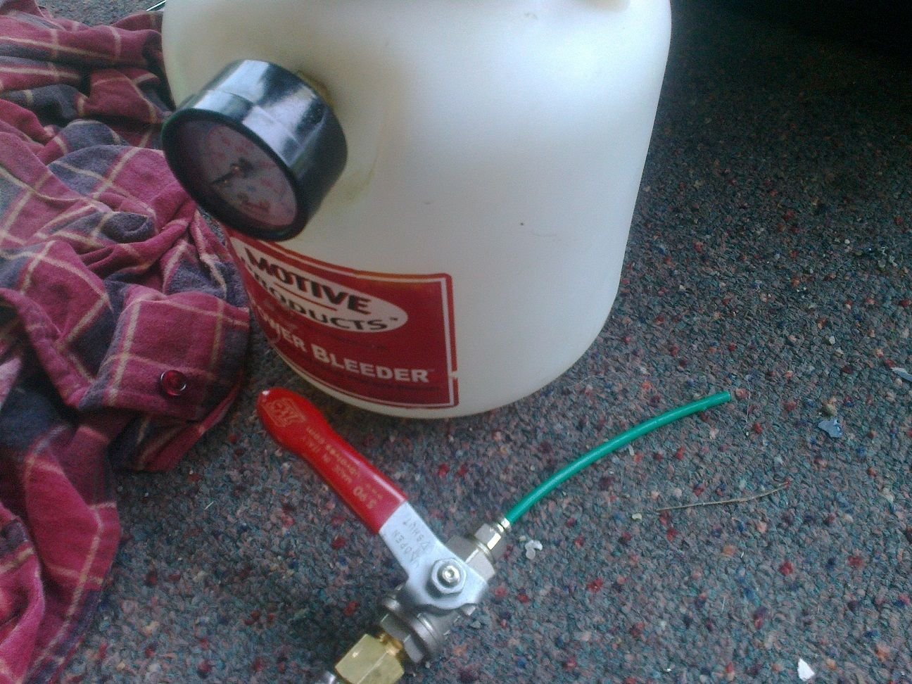
Repurposed a brake bleeder. Added a valve on the end of the pipe and then a 4mm air line with the end blocked off and a small hole in one side.
I used this to flow fluid through each oil line. Later I switched to one with four holes drilled in it to try to make sure I had all side directions covered.
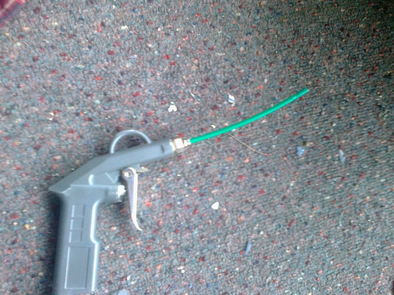
I also used the same 'fitting' in an air gun to help blow out the holes.
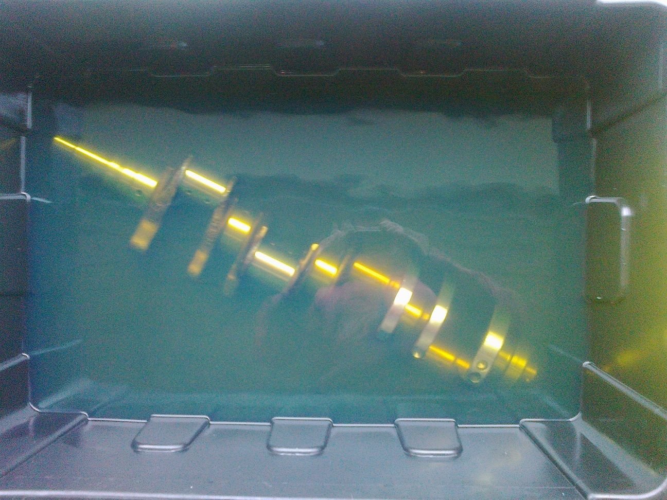
First step was to soak the crank in petrol (think cheap non-corrosive semi-solvent). After immersion I slowly rotated the crankshaft to get all the air out of the oil passages and let the fluid in.
While still immersed, I pumped petrol through each hole from both directions slowly. After completing a run I then blew air through each passage by slowly moving the air gun through each hole. Spent more time at the locations where the petrol or air came out of the adjacent passages.
I then removed the crank from the petrol bath and blew out each passage with the air gun.
I then repeated the process (soak, pump fluid, blow air, blow dry) several times until I felt sure nothing was coming out. I then tested for dirt by running pipe cleaners through each hole I could. Once they came out clean I repeated the whole process again a couple of times.
Final step was to wipe down with a lint free rag then spray liberally with WD40 to stop rust, then put in a plastic bag and store.
The only time I visually noticed gunk coming out from the cleaning process was when I pumped petrol through the front bearing passage. A distinct stream of brown fluid discharged for a few seconds. No other discharge was noticed from any other passages.
I guess only time will tell if I have get everything out. If you are pretty sure I need to do more steps PLEASE let me know.
While I have been waiting for parts to arrive I have been doing some cleaning and making sure I have everything I need in hand.
Today I found out that Loctite 574 is not brought into NZ and, as it is a dangerous good, getting some sent to me is an issue.
UPDATE: Amazon seem quite willing to send Loctite 574 to NZ. I have ordered some from there.
A 'local' Porsche specialist in CHCH (5hrs away) has advised that they have used wurth flange sealant p/n 0893574050 in the past with success.
UPDATE: Wurth tell me that either this or p/n 189082180 are their equivalents.
Anyone have any experience with this or another alternative.
I do have access to loctite 518 which I used for the cam cap bridges 9 years ago without issue and appears to be a similar product to the 574, at least according to the loctite website.
UPDATE: Loctite tells me the best equivalent available in NZ is their 518.
Update 24/12/21
While I wait for some parts to bounce around the USA (instead of heading to NZ) I have:
dropped the rear suspension, torque tube & transmission.
Set up the main bearings & measured clearance with plastiguage. All were 0.05mm to 0.055mm. (Specs is 0.020 - 0.098mm for new, wear limit 0.16mm, so right in the middle)
Searched frantically for the front locating bush fur the cradle only to find out that it never had one, didn't need one and that using one would cause significant problems.
Sourced some Loctite 574 (from India of all places!). Applied this twice (cleaned off between) as contaminated first roller with assembly lube from one of the bearing shells.
Assembled cradle to block with all new nuts. Torqued as per WM including all M8 bolts within the sump and on the outsides.
Next on list is to tap sump pan for GST oil baffle & cam covers for Precision MW's breathers.
Pistons / ring fitting will foll after that.
Also have sourced new commutator & brushes for blower motor as unable to source replacement so will try rebuild.
Myles
Really should get Rogers replacement motor, with better wiring...moves more air quieter too.
Update 24/12/21
Next on list is to tap sump pan for GST oil baffle & cam covers for Precision MW's breathers.
Pistons / ring fitting will foll after that.
Myles
GTS baffle installed.
Breathers installed. (not allowed to show detail)
I started test fitting the new goetz rings into the bores. As far as I can tell from the workshop manual the two compression rings should have a new gap 0.20mm - 0.40mm and the oil ring 0.40mm - 1.20mm.
I am getting a consistent gap of 0.45mm on all rings, both at the top & bottom of the bore extents traveled by the rings. (Only opened two of the 8 packets to date but don't want to not be able to return if need different rings).
Have I got the wrong gap specs?
Have I got the wrong rings (recognized 928 supplier)?
How do I get rings to be in spec?
Hopefully you will get some expert input later today [I am no expert ] but when you quoted the WSM I was a little surprised at the low end WSM number of 0.2mm. The rule of thumb I am used to seeing for naturally induced engines is 4 thou per inch of bore for the compression rings so for a 100mm bore size that would imply 16 thou- your measure is 18 thou.
Presumably the fact that the block is alloy and expands nearly twice as much as a cast iron block may of course influence such as will the fact that the pistons and rings will heat up quicker than the block. There again the alloy will conduct heat way better than steel. The top ring will operate hotter than the 2nd ring and the scraper ring. Ring stagger is also applied to reduce blow by through the gap.
Presumably you measured the gap at the proscribed bore depth and with the girdle torqued up [as specified in the WSM]. It will be interesting to see opininos as to what is considered critical.
Not related but did you also measure the gap at mid bore to help verify bore wear- maybe you have measured this separately already?
Hi Fred.
The new rings are giving very similar end gaps to the original ones I am replacing.
I, too, am aware of the general 0.004" gap per inch diameter rule. The WSM certainly gives different numbers (If I have understood it directly).
I could not find a prescribed depth in the bore to measure the ring gap. Measured at both ends of ring travel.
I have measured bore wear with a bore gauge and measured the old ring gap at several depths to check for consistency.
Hallo.
0,2 bis 0,4 mm sind richtig.
0,45 mm sind auch kein Problem.No height is given in the manual.
A little too much play of the piston rings isn't that bad, a little more blowby. Too tight could lead to engine damage.Deine Zylinder sehen echt toll aus.
Hallo.
0,2 bis 0,4 mm sind richtig.
0,45 mm sind auch kein Problem.No height is given in the manual.
A little too much play of the piston rings isn't that bad, a little more blowby. Too tight could lead to engine damage.Deine Zylinder sehen echt toll aus.
What an interesting and informative thread. I am going to purchase an SST technology kit, wondering if you think this would fix the pitting in the Heads' surfaces? https://www.supersonicspray.com/appl...m-applications

 09-28-2021, 10:32 AM