When you click on links to various merchants on this site and make a purchase, this can result in this site earning a commission. Affiliate programs and affiliations include, but are not limited to, the eBay Partner Network.
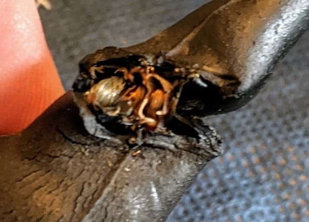
At the moment I am in the middle of trying to revamp the LH/EZK harness and intend to change out the injector pigtails, the MAF pigtail, the Temp2 pig tail, the CPS pigtail as these items look a bit dodgy. I may also change out other pigtails and I have some new connectors and some good condition pigtails from my late S4 harness. What I found with both harnesses was that the main cable runs located inside the heat shrink are in good shape but the cable located outside the main runs as it enters the connector tend to be crispy fried.
I will post some pics shortly but I have three specific questions. I want to liberate the harness at the back of engine to gain better access to it but currently have some problems in that regard.
1. Just behind cylinder No8 there is a pigtail with two cores in it that appears to run round the back of the cylinder head and based on my spare harness config it appears to engage a barrel type connector- at the moment I cannot lift the car so cannot get to view the pigtail- any suggestions as to what signal it is carrying- does not appear to be screened.
2. I would like to undo the 3-way connector that carries the idle switch and WOT switch- is it possible to liberate this and get it back on with the inlet manifold still on? Looks impossible to me.
3. I also want to undo the Hall sensor connector . I fear the male connector may crumble but will deal with that if it does. At the moment I cannot get at it because of the engine hook- is it possible to remove this in-situ? One bolt should be OK but the second one looks decidedly dodgy. I am thinking of interdicting this cable and then splice it back into the loom but given it is screened I prefer not to touch it- I have a procedure for splicing it if needs be.
1. Cylinder Head Temp sensor. They clip in to a plastic support. Literally pop apart once removed from the plastic clip. You can reach it from above,. At least I have.
2. ISV - Damn near impossible without some serious gymnastics. I've done it with a set of double jointed pliers and wiggled it off. Throttle position switch is easy. Wiggle.
3. Search for a recent post on how to do it. Panter928 I think started the thread.
I've refurbished a few harnesses, always with new connectors and pins. I prefer the new(er) style connectors with the spring lever over the fixed wire style our cars come with. I leave the boots off since the newer connectors have a built in WeatherPac style seal making the boot unnecessary except for looks.
I started doing this after about 15 years ago when I found the Ferrari world this is a common task to replace the pins. A vendor sells a kit with all new pins and loans out the tools to install them (connectors are re-used unless damaged). https://www.ferrarichat.com/forum/th...he-348.236795/
Theory behind this is the pins get corroded / dirty and lose some of their spring tension.
I'd never splice in a pig-tail unless it was a last resort. If there isn't enough good wire to crimp on (never solder) new pins, time to buy a new harness.
Photos from that thread since I think you need to be a member to see them:
1. Cylinder Head Temp sensor. They clip in to a plastic support. Literally pop apart once removed from the plastic clip. You can reach it from above,. At least I have.
2. ISV - Damn near impossible without some serious gymnastics. I've done it with a set of double jointed pliers and wiggled it off. Throttle position switch is easy. Wiggle.
3. Search for a recent post on how to do it. Panter928 I think started the thread.
Kevin
Kevin,
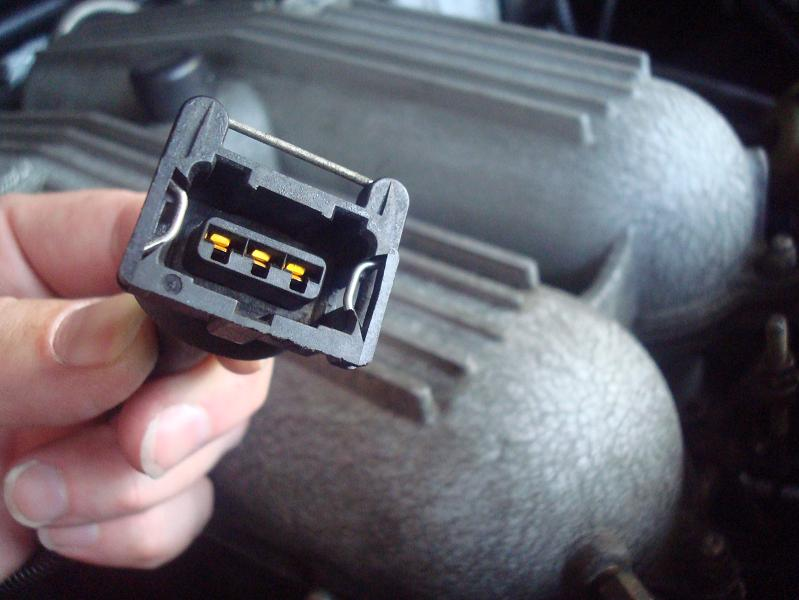
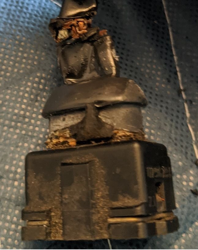
Pic of the connector I am trying to trace- there is one each side of the engine and your suggestion makes sense- it is the cylindrical connector.
The ISV is easy- 15 years ago I removed the spring clip from the connector. In this revamp I am thinking about fitting an additional connector outside the inlet manifold and then use the stock connector with a spring clip once more - even so never had a problem.
I will take a look at the idle and WOT switch connector- I am fairly imaginative about such things but that one has me beat at the moment.
I cannot lift the car at the moment as my Chinese jack conked on me the other day. Looking for a half decent trolley jack at the moment.
I prefer the new(er) style connectors with the spring lever over the fixed wire style our cars come with. I leave the boots off since the newer connectors have a built in WeatherPac style seal making the boot unnecessary except for looks.
Theory behind this is the pins get corroded / dirty and lose some of their spring tension.
I'd never splice in a pig-tail unless it was a last resort. If there isn't enough good wire to crimp on (never solder) new pins, time to buy a new harness.
Eric,
Agree with you about the newer type connectors and have ordered a batch of them for the ones I originally planned to replace- unfortunately cannot fit them on the temp2 and panel temp senders as they will not fit on due to extra width- maybe I can fit another copper washer to alter the orientation but not sure I want to touch them..
The problem with the cable cores is the last 3 inches or so of cable get crispy fried and then after circumcising them the core is just too short. I have spliced cables using solder but prefer not to use such. Where my views differ from yours is with respect to crimps- use a quality crimp of the correct size range and crimp with a quality ratchet type crimper and as I am concerned one cannot go wrong.
I may be able to get a bit more slack to work with if I disconnect the plugs and connectors in the footwell and push the loom through as though I were removing the engine- I find that a bit intimidating but should be perfectly doable. I have so much disconnected at the moment I am now thinking to remove the fuel rails and pull the inlet manifold to create room to work in as it were.
The trouble with these things is that once one starts one wants to do a decent job of it and then forget it for another how many years. I managed to unravel one mystery last night- I wondered how Porsche managed to get 4 fuel injector wires out of one supply line- guess what?- they used a crimp buried in under the shrink wrap.
The most difficult part of the task is getting the crispy fried shrink wrap cut open without gouging the cables inside- I am getting rather good at that!
1. Cylinder Head Temp sensor. They clip in to a plastic support. Literally pop apart once removed from the plastic clip. You can reach it from above,. At least I have.
Got those things undone today- like you said they sit in clips and simply pull out. Still baffled as to what they do and how they do it though.
Bit the bullet this morning and removed the inlet manifold to get better access to the cabling and also to inspect how my home brew breather system is holding up- may even try to make it a bit more long term as what I used mostly came out of a plumber's store and old pieces of hose. Now waiting for new connectors to arrive from UK and some goodies from Roger.
To get better access to the Hall sensor connector it looks as though I would have to demount the ac compressor to get the bolt- urrgh!
Those are exhaust temperature probes.
If you are ordering from Roger, ask for the ISV extension harness SeanR makes. No more reaching under the manifold.
A few long 1/4" extensions after removing the front engine support will get you to the hall sensor allens.
Those are exhaust temperature probes.
If you are ordering from Roger, ask for the ISV extension harness SeanR makes. No more reaching under the manifold.
A few long 1/4" extensions after removing the front engine support will get you to the hall sensor allens.
Presumably the exhaust temperature probes plug into that piece- however I understand I do not have such as I do not have cats and no relays to trip.
I already have the bits to make the ISV extension- just never fitted them! However leaving the spring clip off works just dandy- it has never worked loose in nigh on 10 years.
1. Just behind cylinder No8 there is a pigtail with two cores in it that appears to run round the back of the cylinder head and based on my spare harness config it appears to engage a barrel type connector- at the moment I cannot lift the car so cannot get to view the pigtail- any suggestions as to what signal it is carrying- does not appear to be screened.
2. I would like to undo the 3-way connector that carries the idle switch and WOT switch- is it possible to liberate this and get it back on with the inlet manifold still on? Looks impossible to me.
3. I also want to undo the Hall sensor connector . I fear the male connector may crumble but will deal with that if it does. At the moment I cannot get at it because of the engine hook- is it possible to remove this in-situ? One bolt should be OK but the second one looks decidedly dodgy. I am thinking of interdicting this cable and then splice it back into the loom but given it is screened I prefer not to touch it- I have a procedure for splicing it if needs be.
Hi, Fred. Happy to provide any help i can as have performed the nuclear option with my '89 where I had a new ignition harness made and am working through issues now. I had gone the pigtail route for a while, but there was too much that got crispy and shorted. I had to get a new one made by Kroon Harnesses (through 928 Motorsports in the US) as I could not find a used one on the market at the time.
To answer your questions:
The barrel connectors behind cylinders 8 and 4 are the thermo-elements that sit in plastic brackets. These barrel connectors connect the Ignition Control Module to sensors in those cylinders that read temperature. If one is much colder than the other (as in not firing), it alerts the Ignition Control Module which puts the car in 4-cylinder "limp home" mode. Otherwise you will get gas in the catalytic converter which could catch fire. They are very difficult to separate as the rubber casing keeps them tight, but they can be pulled apart. Getting them together is more difficult as you need small hands. I actually bought some long nose needle nose pliers to see if that will help for me.
Connectors to ISV and Throttle are tough to remove. Once you have removed the MAF, you basically have to tug aggressively to remove them from those connectors as there is no way to remove the old harness wire bale that holds them together. With the newer Bosch connectors the wire bale is replaced by a push wire, so they are easier to connect and disconnect. the ISV is very difficult to do as you have to do it blind, though I used an endoscope to help me watch my progress so I could snap it in.
Believe it or not, removing the Hall Sensor was easy for me. I read up on how to do this on Rennlist and the combined suggestions worked for me. You would think removing the engine hook should be an act of God as it is supposed to hold the engine, but it simply screws off. The key of getting the hall sensor off for me (as long as it wasnt molested by someone else) was that I had a very long allen bit (7") with a ball end that fit into the screws of the hall connector. The ball end allows the bit to not have to sit perfectly straight in the screw, as you are on a slight angle. By spraying penetrant on the screws the night before, then using the bit to add a fair amount (but not stripping strength) of unscrewing pressure on the bolt, while also tapping the bolt head to send vibrations to break the threads free, was the ticket. There was a loud "crack" which made me think cracked the screw, but then it unscrewed nicely and was able to get it off and replaced in about 20 min. This process worked for both bolts and can be done from above the engine, as I remember.
Presumably the exhaust temperature probes plug into that piece- however I understand I do not have such as I do not have cats and no relays to trip.
Did you or the previous owner have cats and have them removed? I removed mine, but of course the wiring remains. The thermo-elements are actually not integrated with the LH/EZK at all from my knowledge and run separately to the clear, bigger relay-looking Ignition Control Module (ICM) on the side of the EZK via a white relay-like plug in the harness. The ICM then shuts off the problem bank of cylinders if there is a significant temp issue. While you don't have to worry about your cats catching fire now, the ICM should be able to alert you if a particular bank of cylinders is not firing well. There is a ICM bypass connector that Roger sells that will keep all the injectors powered, or you can make one yourself.
Hi, Fred. Happy to provide any help i can as have performed the nuclear option with my '89 where I had a new ignition harness made and am working through issues now. I had gone the pigtail route for a while, but there was too much that got crispy and shorted. I had to get a new one made by Kroon Harnesses (through 928 Motorsports in the US) as I could not find a used one on the market at the time.
To answer your questions:
The barrel connectors behind cylinders 8 and 4 are the thermo-elements that sit in plastic brackets. These barrel connectors connect the Ignition Control Module to sensors in those cylinders that read temperature. If one is much colder than the other (as in not firing), it alerts the Ignition Control Module which puts the car in 4-cylinder "limp home" mode. Otherwise you will get gas in the catalytic converter which could catch fire. They are very difficult to separate as the rubber casing keeps them tight, but they can be pulled apart. Getting them together is more difficult as you need small hands. I actually bought some long nose needle nose pliers to see if that will help for me.
Connectors to ISV and Throttle are tough to remove. Once you have removed the MAF, you basically have to tug aggressively to remove them from those connectors as there is no way to remove the old harness wire bale that holds them together. With the newer Bosch connectors the wire bale is replaced by a push wire, so they are easier to connect and disconnect. the ISV is very difficult to do as you have to do it blind, though I used an endoscope to help me watch my progress so I could snap it in.
Believe it or not, removing the Hall Sensor was easy for me. I read up on how to do this on Rennlist and the combined suggestions worked for me. You would think removing the engine hook should be an act of God as it is supposed to hold the engine, but it simply screws off. The key of getting the hall sensor off for me (as long as it wasnt molested by someone else) was that I had a very long allen bit (7") with a ball end that fit into the screws of the hall connector. The ball end allows the bit to not have to sit perfectly straight in the screw, as you are on a slight angle. By spraying penetrant on the screws the night before, then using the bit to add a fair amount (but not stripping strength) of unscrewing pressure on the bolt, while also tapping the bolt head to send vibrations to break the threads free, was the ticket. There was a loud "crack" which made me think cracked the screw, but then it unscrewed nicely and was able to get it off and replaced in about 20 min. This process worked for both bolts and can be done from above the engine, as I remember.
Hope these suggestions help!
Jason,
Thanks for the thoughts- I have a spare harness from my deceased 90S4. I am changing most of my connectors to the later type and they are due here in a few days time. Experience from the S4 and inspection of my current harness show similar characteristics in that only the last 3 or so inches of the wiring is affected by the heat etc- it seems the heat shrink protects the cables within. I have harvested the pig tails from the 90S4 harness and clipped the wires deeper into the harness after removing the crispy fried remains of the original heat shrink. Thus for the most part I can retain the original colour coding of the wires. I have made new pigtails for the injector connectors and used red and black cores for that.
Every 928 delivered new here does not have cats fitted as the refinery was still producing leaded gasoline at the time they were delivered and only changed over to lead free gasoline just before i joined them as chief engineer in 1994. Seems they used the same wiring harness but did not fit the final elements..
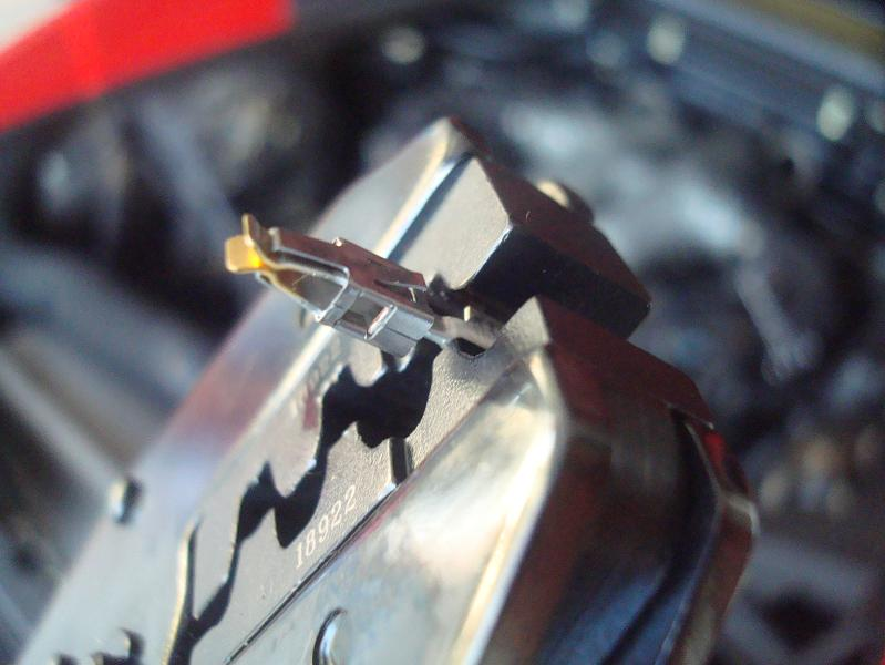
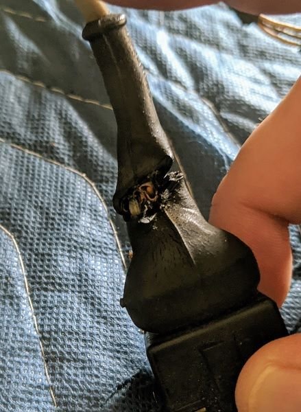
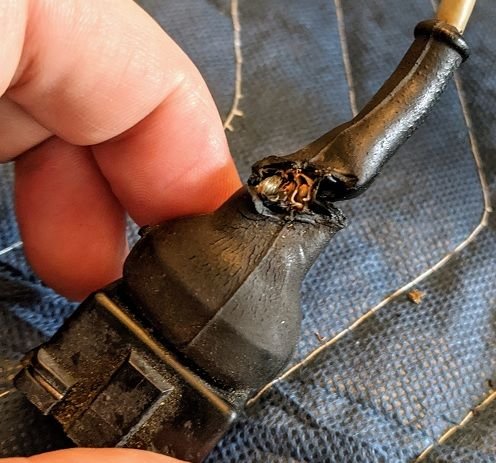
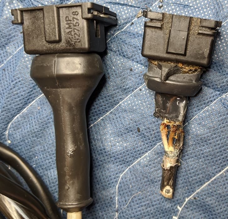
I took the time to revamp my harness in my 87-S4 while the engine was out of the car. Really nice to sit at the dining room table and do it rather than bending over the engine bay. Most of the engine side connectors were shot with wire showing in places. Roger supplied the replacement clips and pins. Here are some before and after images:
I took the time to revamp my harness in my 87-S4 while the engine was out of the car. Really nice to sit at the dining room table and do it rather than bending over the engine bay. Most of the engine side connectors were shot with wire showing in places. Roger supplied the replacement clips and pins. Here are some before and after images:
Rich
Rich,
i have seen terminals like that 15 years ago. I repaired a few on my current 928 about 5 years ago but planned to go through the job lot this time-. I have a new pigtails ready for the injectors, I have some pigtails ready extracted from my spare harness that were in good condition and I have some new connectors arriving in the next day or two.
On both my currently fitted harness and my spare harness they are both in excellent condition once one gets behind the heat shrink that was used originally. I have half a mind to undo my current harness and pull it through into the engine bay so as to cut out and replace the current heat shrink. Plan at the moment is to replace all connectors and replace with the modern easy release type connectors where possible.
@FredR: I know it might be a ton of work but I think you'd be well served to pull the harness and address things properly. I just finished reworking the full harness on my '91 944 and there are all kinds of things hiding under the boots throughout the harness. Even where wires seem to have been reasonably well protected by the PVC (?, whatever the now-inflexible black tubing is) you can feel that the wires themselves have become significantly less flexible as compared to what you can feel in the parts that go into the passenger area. I know that people on here that really prefer to keep things original looking will disagree with the choice, but I went with putting everything in InsulTherm to try and protect things as well as possible. Granted, the materials that Porsche chose have held up very well for decades (!), so I can't fault the original choices, but I also think that material science and the fruits of its development are much more readily available now to Joe Consumer and should be taken advantage of. At the very least, this is what I plan to do with my own 928 once I get that far; I have all the tools and wiring I need now from my current project.


 02-02-2021, 12:07 PM