
voltage drop at fuel pump

 10-18-2020, 01:11 PM
#17
Chronic Tool Dropper
Lifetime Rennlist
Member
Lifetime Rennlist
Member

With a relatively stock engine, adding the 044 pump is pretty much a waste. So long as the pump you have is able to maintain pressure at load, adding a bigger pump to bypass more fuel does you no good.
In the later cars, the fuel pump relay is wired as the diagram in post 16 shows. The relay is in the CE panel though. Retrofitting the bigger 044 pump demands larger wire sizes, otherwise it's the same relay wired the same, just placed in the back of the car near the battery. In this case the 044 adds nothing.
In the later cars, the fuel pump relay is wired as the diagram in post 16 shows. The relay is in the CE panel though. Retrofitting the bigger 044 pump demands larger wire sizes, otherwise it's the same relay wired the same, just placed in the back of the car near the battery. In this case the 044 adds nothing.
10-18-2020, 01:15 PM
#18
Three Wheelin'
Thread Starter
yes, Ake, we did this many times on the old BMW for the lights , window motors etc... to spare the weak switches.
Could be a good solution if still problems.... sure as the battery is almost near the fuel pump.
Could be a good solution if still problems.... sure as the battery is almost near the fuel pump.
10-18-2020, 07:07 PM
#19
Addict
Rennlist Member
Rennlist Member
I did this on my car, but split the original line to three relays, one for the 044 external, one for the 040 internal pump, and one for the fans (3) for the fuel coolers (2) and solenoid that opens the fuel cell vent.
__________________
George
90 S4 Grand Prix White (Murf #5 - 219.0 mph top speed)
94 GTS 5-Speed Midnight Blue
06 Cayenne S Havanna/Sand Beige (PASM)
http://928.jorj7.com
__________________
George
90 S4 Grand Prix White (Murf #5 - 219.0 mph top speed)
94 GTS 5-Speed Midnight Blue
06 Cayenne S Havanna/Sand Beige (PASM)
http://928.jorj7.com
10-18-2020, 07:39 PM
#20
Former Sponsor

Even 11 continuous amps is quite a bit, for the existing wiring.
I'd highly recommend doing what Ake has shown, with one change.
I've had three of the fuse holders for the blade style fuses overheat and melt, with 044 fuel pumps....from two different manufacturers (using 12 guage fuse holders.) Seems like the constant 15amp draw is just too much for these "Chinese made" pieces.
I now use more robust fuse holders.
10-18-2020, 08:38 PM
#21
Rennlist Member

It should be SOP to use relays as described above for the fuel pump and dual S4 fans.
Somebody should offer kits.
Somebody should offer kits.
 10-19-2020, 01:54 AM
#22
Chronic Tool Dropper
Lifetime Rennlist
Member
Lifetime Rennlist
Member
No benefit for the S4+ fans. The switching is done in the "final stages" module. No relay function.
10-19-2020, 02:02 AM
#23
Chronic Tool Dropper
Lifetime Rennlist
Member
Lifetime Rennlist
Member
There my be other fuel pump options for high-horsepower engines. Submersed pumps that go in from the top of the tank, stuff like that. Electrical concerns stay the same though. Look at Bussman circuit breakers instead of fuses and fuseholders, maybe the self-resetting kind. They are intended to protect the wiring, and with short conductors and relay in the back with air-cooled wiring, a just-adequate self-resetting breaker would be OK with oversize conductors.
10-19-2020, 09:30 AM
#24
Rennlist Member
10-19-2020, 11:05 AM
#25
Rennlist Member
The design of the power supply to the two fans has concerned me since I first read the circuit diagram. The PWM controller is a solid state device 0% to 100% variable and they must be pretty darn reliable as one does not hear much at all about problems with them so if it ain't broke don't fix it! That being said the cables run from the positive post of the battery through to the PWM unit at the very front of the engine bay under the bonnet and one cannot help but wonder what mayhem might be caused by penetration of the protective sheath. Remember the problem Carl had with that car in his garage when the cable from the hot post to the central electrics gave up the ghost?
Bottom line the system will draw whatever current the PWM unit allows to flow through it and once at 100%operating point it plays no further part in the process as the system then becomes self modulating through resistance. If the fan motors are shot then it is what it is.
Bottom line the system will draw whatever current the PWM unit allows to flow through it and once at 100%operating point it plays no further part in the process as the system then becomes self modulating through resistance. If the fan motors are shot then it is what it is.
10-19-2020, 01:19 PM
#26
Chronic Tool Dropper
Lifetime Rennlist
Member
Lifetime Rennlist
Member
I think I remember Roger having a replacement fan motor that has lower current draw. Else you can do some service to the factory motors to restore original function. IIRC the bearings are common, and share size with some rollerblade (in-line skate) wheels, so you can buy some pretty high-precision bearings for not a lot of money. Some searching here will give guidance on the disassembly process, as the motors are not obviously serviceable. Finding brushes may be fun too. There are native motors from period European cars like Vauxhall that fit and function well, but the electrical connectors are different.
Fred, since your fans run pretty much full-time in your warm climate, replacement motors may be your best option, assuming you can get them at reasonable delivered cost. For the bulk of our audience (mostly U.S.), delivery and import duty is not a problem.
For those playing along, power for the S4+ fans is delivered via dedicated conductors directly from the battery, through fuses in the CE panel (28 and 29), and on directly to the "final stages" module on the front apron under the hood. Excessive current draw coupled with contact resistance is know to damage (read: melt) the plastic block in the CE panel where the fuses live. Same deal at the connectors at the fan motors. For most of us, it's worth a look and either motor rebuild or replacement before the wiring, connectors and fuse-holder blocks are damaged by the excessive current draw. It can also extend the life of that final-stages module, so overall it should be a scheduled PM effort. Clean secure connections at the battery positive post are very important.
10-19-2020, 02:35 PM
#27
Rennlist Member
I think I remember Roger having a replacement fan motor that has lower current draw. Else you can do some service to the factory motors to restore original function. IIRC the bearings are common, and share size with some rollerblade (in-line skate) wheels, so you can buy some pretty high-precision bearings for not a lot of money. Some searching here will give guidance on the disassembly process, as the motors are not obviously serviceable. Finding brushes may be fun too. There are native motors from period European cars like Vauxhall that fit and function well, but the electrical connectors are different.
Fred, since your fans run pretty much full-time in your warm climate, replacement motors may be your best option, assuming you can get them at reasonable delivered cost. For the bulk of our audience (mostly U.S.), delivery and import duty is not a problem.
For those playing along, power for the S4+ fans is delivered via dedicated conductors directly from the battery, through fuses in the CE panel (28 and 29), and on directly to the "final stages" module on the front apron under the hood. Excessive current draw coupled with contact resistance is know to damage (read: melt) the plastic block in the CE panel where the fuses live. Same deal at the connectors at the fan motors. For most of us, it's worth a look and either motor rebuild or replacement before the wiring, connectors and fuse-holder blocks are damaged by the excessive current draw. It can also extend the life of that final-stages module, so overall it should be a scheduled PM effort. Clean secure connections at the battery positive post are very important.
Fred, since your fans run pretty much full-time in your warm climate, replacement motors may be your best option, assuming you can get them at reasonable delivered cost. For the bulk of our audience (mostly U.S.), delivery and import duty is not a problem.
For those playing along, power for the S4+ fans is delivered via dedicated conductors directly from the battery, through fuses in the CE panel (28 and 29), and on directly to the "final stages" module on the front apron under the hood. Excessive current draw coupled with contact resistance is know to damage (read: melt) the plastic block in the CE panel where the fuses live. Same deal at the connectors at the fan motors. For most of us, it's worth a look and either motor rebuild or replacement before the wiring, connectors and fuse-holder blocks are damaged by the excessive current draw. It can also extend the life of that final-stages module, so overall it should be a scheduled PM effort. Clean secure connections at the battery positive post are very important.
The fan motors do indeed seem to eat up bearings. I had a spare motor from my late S4 fans and when I acquired the current 928 I noticed that both the fans were noisy as hell. With the ac running most of the time the fan run hours per hour of runtime are probably way higher than cooler climes. At that time some 16 years ago Dave Roberts was introducing his slim line twin fan kit but sadly due to his personal situation could not get the base module converted into his custom setup so I acquired a base kit for some $280 Stateside and had them sent over here.
They lasted me 15 years and last year they were growling some and was about to buy a new $280 kit when I chanced upon a small electrical workshop who rebuild alternators. Asked them if they might be able to put new bearings in my two Spal fans and one hour and $10 later I had what spun like two new fans. Ironically a couple of weeks ago I went to my friendly AC shop to get some compressor oil and spotted a little alcove to the side with some Spal fans on the wall and they had a 13 inch fan with the same motor that drives my fans for an ask of circa $100 bucks so a potential source for a spare motor.
I have had no problem with the fuse holders to date but it is a bit of a worry- they could easily have installed an in-line fuse in the battery compartment. The other "solution" I considered was when I replaced the engine loom with my home built custom version. I rebuilt the line from the starter motor to the ABS post with 16mm2 cable - same size as the feed to the hot post. It is then a short hop to the PWM modulator so if needs be figured that a new feed eliminating those two 4mm2 cables stuck in a harness whose condition I know not could only be a positive thing. Each SPAL fan draws some 14 amps so a biggish load in comparative terms. No problem for the battery to starter motor cable, no problem for the new 16mm2 cable to the ABS post and no problem for a weatherproof in line fuse holder located along the bulkhead to the side and in front of the radiator that would be placed out of sight.
I also had one of the SPAL supplied Metripak connectors melt for no obvious reason so ordered two new ones. I am not sure how the cables connect to the PWM controller- I have never taken them apart to have a look.
10-19-2020, 06:33 PM
#28
Rennlist Member
cleaned the ground at the back , but seemed OK .... wanted to do the same with the wires at the hot post .... to see that bolt was "loose" ! omg, stupid me....never checked it...
Cleaned those connections and torqued the bold.
Let de car idle and see now approx 1V less at the fuel pump . Was 12.5 at hot post , 11.5 at pump.
Hangs much better on the gas now , no "hesitations" like yesterday... maybe solved ! .
(No test drive as it is raining and i have to move 3 perfect dry cars in it to clear the lift.... o well , tomorrow. )
So, if that was "it" , it wasn't the fuel pump ... but ok, i have a new one now and more, the old pump in the car as i bought it , wasn't a Bosch oem one , but worked also perfect before the problems began.
Voltage @ the pump when running idle is 12,5 V. I cleaned all the possible earth connections (especially behind the right side interior panel in the trunk.
I never replaced my fuel pump relay...so perhaps I could gain some voltage here ?
But car is running fine, also at high speed.
10-20-2020, 03:03 AM
#29
Three Wheelin'
Thread Starter
Gerrit , 12.5 V @ pump is perfect , no need for a new pump relay... ! perhaps your alternator is already charging at idle ? ( idle rpm ? )
To be able to compare, measure voltage at hot spot and pump , both at idle of course.
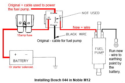
I assume we all can expect a drop of 0.5 ....1 V unless we wire it with a relay as the pic here mentioned in post #16 by Ake.
If my problems seems solved, i will do that extra relay conversion , just to spare the (old) oem circuit from the continuous 11 amps.....as Greg reminded us.
In our "CIS" cars it is the heaviest amp consumer (and obvious needed all the time) ... except all the lights "on" which will be approx the same amps , perhaps a bit more.
Followed by the ignition ... correct me if i'm wrong but i had the thought that is around 7 amps.
To be able to compare, measure voltage at hot spot and pump , both at idle of course.
I assume we all can expect a drop of 0.5 ....1 V unless we wire it with a relay as the pic here mentioned in post #16 by Ake.
If my problems seems solved, i will do that extra relay conversion , just to spare the (old) oem circuit from the continuous 11 amps.....as Greg reminded us.
In our "CIS" cars it is the heaviest amp consumer (and obvious needed all the time) ... except all the lights "on" which will be approx the same amps , perhaps a bit more.
Followed by the ignition ... correct me if i'm wrong but i had the thought that is around 7 amps.
10-20-2020, 01:20 PM
#30
Chronic Tool Dropper
Lifetime Rennlist
Member
Lifetime Rennlist
Member
The design of the power supply to the two fans has concerned me since I first read the circuit diagram. The PWM controller is a solid state device 0% to 100% variable and they must be pretty darn reliable as one does not hear much at all about problems with them so if it ain't broke don't fix it! That being said the cables run from the positive post of the battery through to the PWM unit at the very front of the engine bay under the bonnet and one cannot help but wonder what mayhem might be caused by penetration of the protective sheath. Remember the problem Carl had with that car in his garage when the cable from the hot post to the central electrics gave up the ghost?
Bottom line the system will draw whatever current the PWM unit allows to flow through it and once at 100%operating point it plays no further part in the process as the system then becomes self modulating through resistance. If the fan motors are shot then it is what it is.
Bottom line the system will draw whatever current the PWM unit allows to flow through it and once at 100%operating point it plays no further part in the process as the system then becomes self modulating through resistance. If the fan motors are shot then it is what it is.
I don't have a wiring diagram set for Barry's ROW car, so don't know if the fuel pump has a dedicated feed from the battery or feeds from the jump post primary wiring to the CE 30 bus.