When you click on links to various merchants on this site and make a purchase, this can result in this site earning a commission. Affiliate programs and affiliations include, but are not limited to, the eBay Partner Network.
Andy, I'm a believer in Trans-X, short of a rebuild, for things that could be a sticky valve. It MAY have helped this 30 year old NOS tranny a bit. I don't think it does any harm to try it before ripping into the valve body, modulator assembly or B1 piston.
Late to the discussion --
The vacuum you want to the modulator decreases as the throttle is opened and load increases.
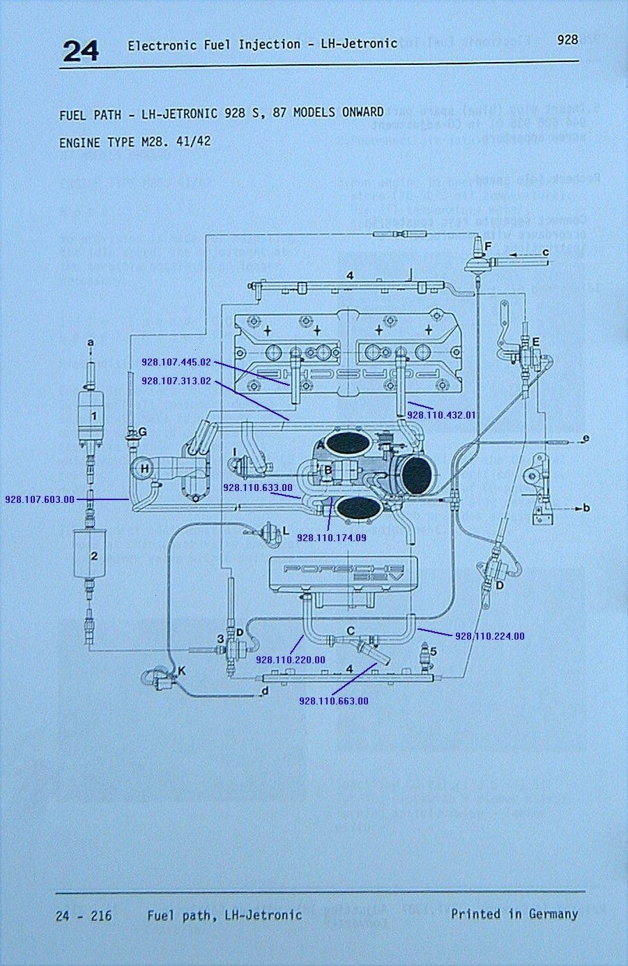
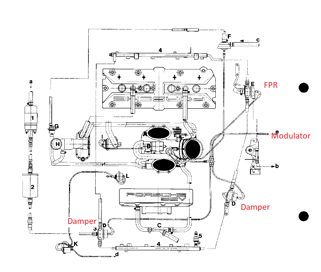
The modulator (and the FPR...) need to see actual intake pressure downstream of both the throttle and the supercharger. Pretty much what the intake valves see. I don't know where the throttle body fits in your Keel installation, but if it's upstream of the kompressor you'll want to move the loa- sensing vacuum connections (FPR and AT modulator) so they see actual engine manifold pressure. The entire 5-way, which includes the modulator, FPR and dampers get vacuum from the throttle. The system is configured:
Air filter -> MAf -> Throttle -> supercharger -> manifold
I understand having fuel pressure rise with load seems desirable, but I was informed by Andy that the 87+ FPR does not respond to positive pressure. I guess I should check that. Some people add Begi and other FPRs that do. I thought Sharktuning would obviate the need for a rising rate FPR. That's the way I ran my earlier kit. Also, I don't understand why the modulator needs to see manifold pressure. Once the vacuum is gone I think the modulator no longer reduces trans fluid pressure and that's it. What would exposing this vacuum device to positive pressure do? The throttle body vacuum port worked well for the modulator on my previous kit.
The dampers should be plumbed to a port that never exceeds atmospheric pressure; Those connections are only needed to support a leaking diaphragm. I don't understand the second sentence above. Anyway the diaphragms are intact.
If you've been sharktuning with the FPR reading somewhere other than actual engine intake pressure, you'll want to take a new look at the higher-load cells, as the fuel pressure profile will now more closely follow load.
The vacuum system that used to include the little Venturi was there to maintain vacuum when the engine is under high load, so the vacuum-actuated HVAC, flappy, and cruise control functions can be maintained while full-throttle cruising. The system is plumbed to the brake booster, but that booster can reservoir has a check valve so there is initial vacuum maintained. This gets more important in supercharged and turbocharged cars. There's a far-out chance (same as 'always') that you would want to have full vacuum brake boost available while the engine is at full load, and it was an easy connection to make. Point being that the "load sensing" vacuum system is different from the brake booster and accessory system, and also different from the ported vacuum system that provides distributor vacuum advance based on charge velocity through the throttle body. Andy included a port that could act as a venturi on an intake adapter just before the supercharger inlet. I never noticed any A/C or brake anomalies.
If this helps: FPR and transmission modulator should be plumbed to the same port where your boost gauge is connected. Of course, the boost gauge is plumbed to the manifold. So, you think I should move the FPR and modulator there, leaving the dampers on the current throttle body source?
Originally Posted by FredR
Bill,
First of all the whole point of these forums is to work on the premise that many hands make light work- it is somewhat foolish to have issues and not discuss them.
My views on the Bowden cable [ I refer to it as the kick down cable assuming we are talking about the same thing] may not please everyone but as I am concerned the stock method for setting the Bowden cable is somewhat deficient. As I recall the stock setting is such that the cable should be set with the cable one turn slack after the cup aligns with the socket- I set mine about 3 to 4 turns tighter than the WSM procedure. I did this initially to facilitate first gear starts as I found the second gear starts somewhat awful. Nowadays I also run with the kick down bypassed as well. My adjustment criteria is set by what happens when rolling on at about 70mph. Gentle throttle pressure should allow to car to roll on without shifting but anything more than a gentle touch and it changes down instantly. As I am aware this does not change the shift points per se but it makes car feel much more alive.
Needless to say it is one thing ensuring first gear starts with ease every time but that does not mean one has to take off like a bat out of hell every time. As I am concerned if the box cannot handle first gear starts it should not be on the car- common sense being the order of the day. This mod coupled with the PSD system makes driving the thing effortless- just wish it had the 6 speed box in my Cayenne Turbo S [and its power delivery for that matter].
The WSM adjustment for the Bowden is "no tension". I took the slack out and it did affect shift points, and at what pedal point downshifts occured, as you mentioned. It's is the number one item under WSM troubleshooting for harsh shifting.
Originally Posted by worf928
What I know about automatic viscous-coupled transmissions in general and the 928’s automatic transaxle specifically might fill a thimble; 90+% of my clients are 5-speed owners.
With that caveat, I have had issues with the kickdown cable. But those issues translated into shifts at the wrong RPM not shift firmness IIRC. I can imagine that there might be a relationship between the two such that a messed up kickdown cable might cause your issue. But, 2mm is not, I think, sufficient mis-adjusment.
Your post helped jog my memory. And also - see above - that I needed to rethink for the kickdown cable.
The “fuel stuff” needs to see the external pressure at the injector. Thus they need to be plumbed after the supercharger as you wrote and not as I posted above.
The lines from the stock 5-way and the 4-way at the booster need to be plumbed differently on a positive displacement SC (like the Keel kit.) Everything but the ”fuel stuff” should get vacuum from between the throttle plate(s) and the supercharger inlet such that they see more-or-less the same vacuum behavior as they would in an N.A. engine (e.g. 17-18 vacuum at idle to ~0 at WOT.)
If the stock 87+ FPR responded to boost like a rising rate FPR, I would be surprised. I was told it doesn't and a lot of people have wasted money on rising rate FPRs if the stock one does that. My simple minded understanding of the stock FPR is that it just reduces pressure at idle or very low throttle states. So, with modest (5-8 PSI) boost do I really need a rising rate FPR or is Shakrtuner going to be adequate. I used Shartuner with my previous kit and was happy enough. Fueling seemed satisfactory.
Originally Posted by Lizard928
I browsed through but not extremely thoroughly.
What is the level of vacuum that the modulator sees with the car at full operating temp idling? I think about 18 inches
I would recommend that you monitor the vacuum level with the car driving (at the transmission with a T fitting). If I continue to experience harsh 1-2 upshifts, I will do that.
I am working on rebuilding a Keel kit that was on an 87 and drove great and then didn't. The intake leaked more boost than it held and through everything out of whack.
The top plate is held to the surround with mostly just sealant. The bolts holding the IC to the top pate were all leaking as were IC pipe connections. The lower plate had some weld ground down and it was completely split left to right and would have leaked really badly.
I've welded the top plate to the surround as well as welded in new injector pieces and am in the process of redoing the IC mounting to ensure everything is as rigid as is needed.
I'm also making it so that the IC can be pulled off without pulling the entire intake off so assembly is MUCH easier.
My point with those comments is that it is likely that you have many vacuum and boost leaks which will vary drastically as you drive.
It is also possible that the seals and valve body in your old transmission had a slightly higher leak past rate which can also affect how the transmission shifts etc.
I too had lots of problems with poor welds and other leaks with my previous Keel kit. This one was heavily modified to insure good sealing. I did have to remake some gaskets to get it to seal to the heads and the intake adapter, but it seems air tight now.
I doubt very much that someone with you pedigree and with access to ST would fail to notice something that was obviously wrong with the configuration so I think we can rule out that possibility. The s/c itself will only develop boost if there is resistance to flow and if the air stream entering the compressor is at a partial vacuum it will only displace a constant volume at that absolute pressure and compressor speed. Whether or not your vacuum sensor location responds the same way as the normally aspirated version remains to be seen but an interesting point for discussion.
On the other hand, your tranny being new and having sat on the shelf for 30 years, maybe that just needs to be "run in" a bit before everything starts working just as it should.
If the stock 87+ FPR responded to boost like a rising rate FPR, I would be surprised. I was told it doesn't and a lot of people have wasted money on rising rate FPRs if the stock one does that. My simple minded understanding of the stock FPR is that it just reduces pressure at idle or very low throttle states. So, with modest (5-8 PSI) boost do I really need a rising rate FPR or is Shakrtuner going to be adequate. I used Shartuner with my previous kit and was happy enough. Fueling seemed satisfactory.
If the current plumbing is identical to the old plumbing then surely everything should work now as it did then?
AFAIK the stock fuel stuff doesn�t do anything with positive pressure.
Last, it�s been 12 years (Holy Flying Time Bat Man) since I�ve thought about or touched my TwinScrew for anything other than scheduled stuff. I�d better go refresh my mental picture of its plumbing before commenting further.
If the current plumbing is identical to the old plumbing then surely everything should work now as it did then?
AFAIK the stock fuel stuff doesn’t do anything with positive pressure.
Last, it’s been 12 years (Holy Flying Time Bat Man) since I’ve thought about or touched my TwinScrew for anything other than scheduled stuff. I’d better go refresh my mental picture of its plumbing before commenting further.
you and me both. I am thinking of sending my AutoRotor to Kennebell to have it overhauled. New bearings etc. Other than that i havent done squat to mine (changed gear oil) and would really have to study my whole set up again as well. Going through my tupperware parts bin I found an overhaul kit for a BEGI fuel regulator!(gaskets..o rings..needle valves)
So, I eye-balled my ‘91GT and the five way to the ‘fuel stuff’ is plumbed between the throttle plate(s) and the supercharger inlet. There is one ‘mystery’ vac line from the 5-way that goes ‘somewhere.’ Guess I’ll need to break out the install manual (that I wrote 13 years ago) and re-figure out where that goes. It ain’t a line to an automatic transaxle, I’m pretty sure...
It might be the air pump diverter valve. The 5 way is: 1. Vac source 2. FPR 3. Rear damper 4. Front damper 5. diverter valve.
Bill,
I detect a touch of brain fade! just a question of whose brain Ha ha! - the air pump diverter valve has a separate connection upstream of the throttle butterfly. As I recall No 5 is the tranny modulator not the diverter valve.
MY CONFIGURATION:
1. Vac source
2. FPR
3. Front + Rear damper (added a T)
4. Diverter
5. modulator
Here is the stock diagram: It is different but functionally not different enough to matter.
1. Vac source
2. FPR
3. Rear damper
4. Front damper
5. modulator
The diverter valve and evap valve are on the other throttle body source. I may change mine to be stock. Also, I will say, without a stock system in front of me, the vac source for the diverter valve (I) is actually not clear to me in this diagram. My air pump belt is not on anyway. I could pull the diverter valve vac off and get rid of the T between the FPR and damper to give them the stock configuration.
So, if the A/P valve is plugged into the 5-way, where�s the transaxle modulator (TM) plumbed? Originally you posted that the TM was in the 5-way?
This S3 throttle body you�re using? Was it modified for the Keel kit? Or is it �stock?�
Sorry about the mistake in describing my configuration. Hope it is clearer now. The S3 throttle body is stock. Here's a photo of the overall installation.
Sorry about the mistake in describing my configuration. Hope it is clearer now. The S3 throttle body is stock. Here's a photo of the overall installation.
Bill, I can't find the S3 throttle body in there and in any case, I don't know that one very well.
If you've got the fuel stuff and modulator plumbed for vacuum between the throttle plate and supercharger AND you are using the vacuum source with max vacuum at idle and no vacuum at WOT then the system is correctly plumbed as far as I know.
The air pump though, and not that it matters for this, should not be plumbed in the same way.
Here is picture of the S4 throttle body with the tiny hole for the diverter valve source in the picture center. The throttle plate is cracked open just a bit so you can see it. At idle the port is covered by the plate. As a result the vacuum behavior of that source is bizarre. More than 10 years ago I gauged that line. If I recall correctly you see no vacuum at idle and no vacuum a WOT. You do see vacuum with partial plate opening.

 12-03-2019, 06:46 PM


 and in any case, I don't know that one very well.