When you click on links to various merchants on this site and make a purchase, this can result in this site earning a commission. Affiliate programs and affiliations include, but are not limited to, the eBay Partner Network.
1989 S4
the male side of the knock sensor on the passenger side disintegrated.
I have a bosch 3 wire repair plug for a quick fix until I can do a proper intake refresh.
can anyone confirm proper wire orientation?
I have a braded silver wire-
a yellow-
a black-
looking at the female side with the single notch up-going from left to right?
thanks-
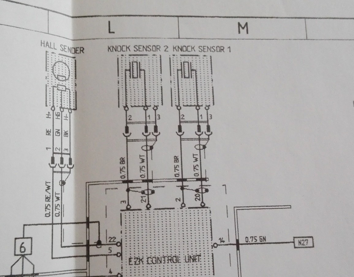
The silver wire is the shield- it covers one of the two other wires. The yellow cable is on the centre terminal so it is a question of deducing which side goes where for the other two.
Looking at the wiring diagram, for the EZK terminal plug, terminals 20 and 21 appear to be the shielded cables for the knock sensor 1 and knock sensor 2 respectively. Unfortunately I am not sure which sensor is which.
The cables on the sensor plug are labelled 1, 2 and 3 where terminal 3 is the shield cable. The shield covers cable 1. Thus if the pin assignment in the sensor plug is logical and the cables are oriented in sequence number, black will be terminal 1, yellow will be terminal 2 and the shield terminal 3
If this logic holds, the black cable of the sensor will be connected to either terminal 20 or 21 [white colour cable] on the EKZ plug and the yellow cable will be connected to either terminal 2 or terminal 3 on the EZK plug depending on which is sensor 1 and sensor 2.
Apologies if this seems a bit confusing but it should be possible to work out which is which from the above. If the terminal assignments in the sensor plug are illogical and go 2, 1 , 3 then we are screwed. Hopefully someone more knowledgeable will chime in/confirm but as you can appreciate, the WSM was never intended for this type of repair.
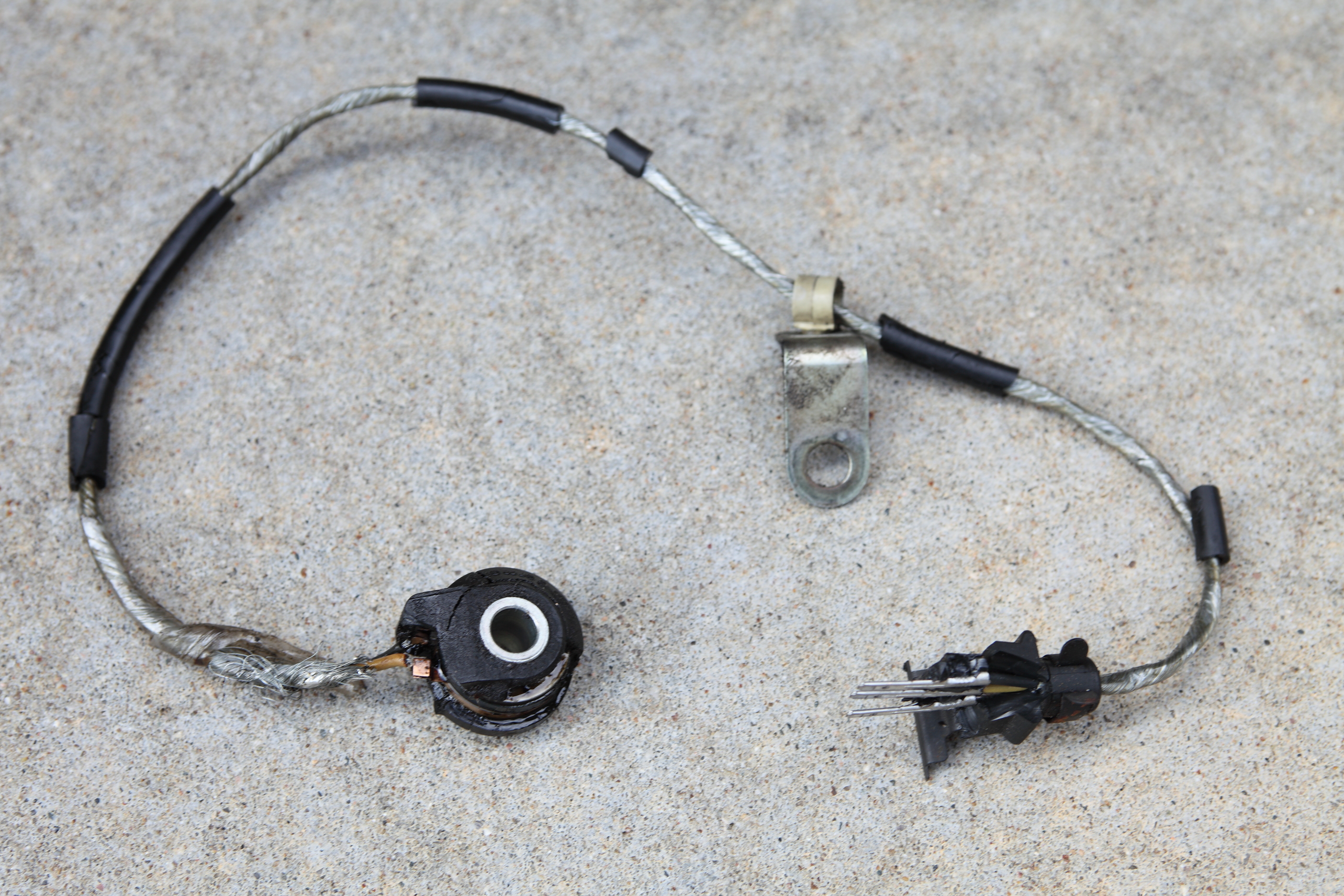
Perhaps this photo of a disintegrated one will help. Looks like it goes black, yellow, shield from top to bottom. Orientation might be derived from the orientation of that clip on the body and/or the orientation of each pin (note that they're a little different on one side vs. the other).
After ripping apart an old one I found that knock sensors have 2 wires and a metal shield that becomes the 3rd pin.
Looking at one with the single notch up, the numbers go 3-2-1, from left to right
3 or left seems to be the metal shield.
2 or middle seems to be white, although the one in my car is yellow
1-is black-far right
On my �89, I was able to replace the rear knock sensor with the intake in place it took some disassembly andremoval of the MAF. If to take the boot off it�s even easier. The 13mm flex head gear wrench may be your best friend on this. I�m not sure it�s a lot tougher than trying to replace the connector alone. Identify the cable path in advance for the new cable and connector.

 10-31-2018, 09:00 AM