When you click on links to various merchants on this site and make a purchase, this can result in this site earning a commission. Affiliate programs and affiliations include, but are not limited to, the eBay Partner Network.
Great Mahle document - thanks Ake (I had to google the filename as clicking the link didn't work for me). Lots of good pictures and explanation of wear marks etc.
Sometimes it is difficult to make the Clevite/Mahle links to work. Your link nor mine does not work for me in spite my link worked when I posted it. If you google until you find a PDF-file named "Table of Contents - Mahle Aftermarket" you should be able to view the catalog.
Ĺke
Getting ready for our trip to Melbourne and the block and crankshaft will receive some more attention. I'm only getting them to bore the block as I think there will be an issue with the sleeves. That will be when you look up from the crankshaft bore and see the start of the bores it's quite thin there. So before the sleeves go in I may need to trim where it may become very thin to keep things tidy. That is best left to me and not when I'm in a rushed situation. The crankshaft will be finished ground but not balanced.
When 3 mm is removed in radius this area will be thin.
However lots of other things have been happening, I have ordered the pipework for the dry sump, it will be internal and not seen. I think you will find this design very interesting. It's part machined and part fabricated, this cuts down on work I have to send out. I have designed it to have five vacuum stages, for a total of 169 mm of scavenge width in the pump. This is not set on stone, if I have to I can delete one 35 mm stage. The pump is an Auto Verdi, with integral oil air separator. The tank is designed with that feature in mind. The engine will still use a PCV system i.e a sealed crankcase and not vented to the atmosphere. The pump should pull a large vacuum, probably greater 2/3 of an atmosphere. If it drops a stage obviously this will be reduced.
To make an Auto Verdi to time it's lobes correctly, it requires the front section to have gears. These gears are precision fitted at the factory so they cannot be played with later. These pumps are very well made with the gears being superfinished and then DLC coated. In terms of operation and efficiency they are probably the best pumps made. This is why most of the Nascar field uses them, Hendricks and Roush to name the two biggest engine builders. However they are not as easy to do a neat installation as are the Dailey pumps which lend themselves to integrated designs.
I've had to design two new pieces for the Auto Verdi so it becomes and all vacuum pump. This means I convert the pressure stage to a vacuum stage. The pump has no external lines, so the oil is plumbed within the pump body and exits the separator as oil or air (one outlet each). To complete this really challenging job I bought a 3D scanner with Solid Edge software. I couldn't use either the scanner or software when I bought them but making progress and designed the first parts this week. Front cover of oil pump, oil pressure adjustor has been deleted
Now I am working on the manifold flange adaptor for the ATPOWER throttles, that is no easy job even if you knew the CAD system well. It's a design challenge, the bolt holes are the issue. Anyway I thought the following would be interesting on a technical level. It's an old graph I forget I had and it's measured at 10" of water. So I have made the conversion to 28" in the following text. The throttle tested was a 42 mm throttle and according to the graph it roughly flows 171 CFM at 10". This converts over to approx 287.8 CFM at 28". So I am using a 45 mm throttle and as such I have more square millimeters in fact it is 1386 to 1591. So I applied this level of flow per mm to the size of throttle that I have and got 330 CFM. This compares to the theoretically maximum flow of 146 CFM at 28" of a straight pipe. That would achieve a flow rate of approx 360 CFM.
Flow graph at 10"
So as I have previously stated I hope to achieve a Max airflow through the heads at peak cam lift of around 315 CFM, the throttle shouldn't impede on that level of flow. It leaves a little free space to not be limiting. So I was pretty happy about that.
curious about moving the valve stems and not using a 944 head with the valves already moved and stock "928 Euro" flow?
The valves are moved in the wrong direction. Well the intake is anyway. If you go to my custom manifold thread I tested a standard head I believe. It's a huge amount of work to use 944 or 968 heads.
The below picture is of my throttle assembly, mocked up by holding it above the port. I'm learning CAD currently and designing the adapter plate is a real challenge as I have areas that conflict with each other, the conflict being bolt holes over lapping each other. Leaving that aside, the total length of the intake runner including the port is approximately 250 mm. Any thoughts? That length of runner allows a perfectly straight tract. You can see the valve seat ring, so this will allow the air to run very fast with hopefully good ram effect if the length is suitable.
Pretty obvious what this is, a honing plate for all my engines.
Lastly, getting a bit serious, my new CNC lathe just arrived before I left for Melbourne, so excuse the mess, it's been very hectic. This will be able to do so many jobs for me like cutting down my valves for the 4 valve engine and making brake hats. I'm going to be busy...
Yes I did look at that thread, luckily my plate didn't cost that amount of money, let's see how we go.*
On another topic but related, cylinder sleeves, I was looking for a way to cut the costs regarding sleeves also is there a better way to do things? Which will be more reliable and stable? The quote I got for Darton type wet sleeves was $2,000 USD per set with *min 2 sets ordered. That is a fair bit of money when you need 2 sets. Also I thought, is it the best way to do sleeves?*
So I came up with an idea that I want to put out there, so the sleeves will look the sleeves I'm putting in this engine.
LA Sleeve
So the sleeves in this format and in this size (4.25" bore) cost approximately $95 USD each. Let's say $800 versus $2,000, However the costs don't end there, given my CNC lathe, I thought I could buy some rather inexpensive pipe and cut lots of ribbing into it for extra surface area and cooling. The sleeves would be pressed into the ribbed outer sleeves. *This ribbed area would extend from the below the deck plate. The deck plate would be about 12 to 15 mm thick and the alloy sleeved ribbed area would be a slight interference fit into that plate. It would then be welded on a jig that would hold the bottom of the sleeves. You could at this point tack the sleeves together also. So they would form a block.*
With that concept you should remember that the cylinders or liners are held in an effective jig at the top by the deck plate and a secondary and temporary jig at the bottom. You would need to preheat the assembly but we have seen from my cylinder head welding which was extensive as it added around 1/2 a kilo of aluminum that distortion need not occur.*
The alloy ribbed area would not touch the bottom of the block but could be made with a third o-ring to seal the cylinders from the sump. That is it would come very close but only the o-ring would compress on the horizontal plane. The assembly would have a minor interference fit into the block. For myself this assembly after drafting out the concept wouldn't save money but may be more stable. Thoughts?*
Greg, how thick is your torque honing plate? It seems to be made of aluminum?
Have you checked out Westwood in the UK about their spun ductile cast iron sleeves. https://www.westwoodcylinderliners.co.uk/
Ĺke
Greg, how thick is your torque honing plate? It seems to be made of aluminum?
Have you checked out Westwood in the UK about their spun ductile cast iron sleeves. https://www.westwoodcylinderliners.co.uk/
Ĺke
Hej*Ĺke,
Yes it is aluminum and it's 1" or 25.4 mm thick. The company I took the block to today also had one which was thicker but the bores were smaller. So they will use mine. They also want a head gasket to use with the plate. I have not checked out Westwood as yet but will, the one thing about LA Sleeve is the quality of the material. I don't think you will get better, also shipping from the UK is always more expensive than the US.*
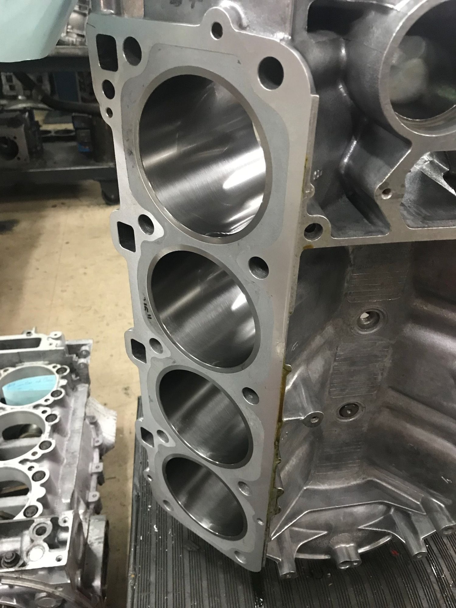
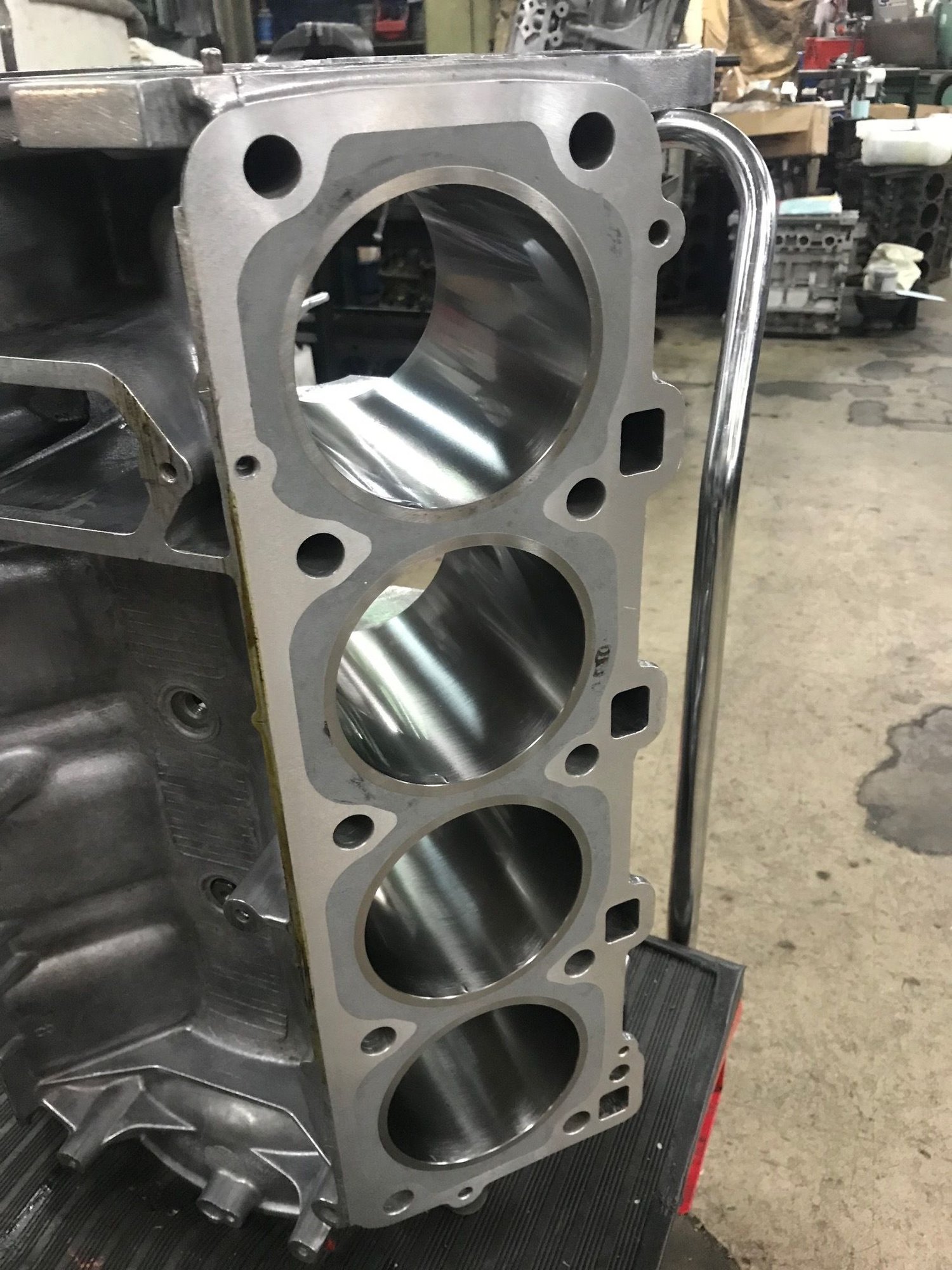
Got these photos from the workshop, I have requested some pictures from underneath however apparently the sleeves fit very nicely. The sleeves were diamond honed and then brushed.
I don't know how to edit the title but the engine is 351 cubic inches or 5751 cc not 5.9 litres, I made a mistake with the input of the maths and we did the minimum with the bores in terms of the final sizing. That's how that happened....
I don't know how to edit the title but the engine is 351 cubic inches or 5751 cc not 5.9 litres, I made a mistake with the input of the maths and we did the minimum with the bores in terms of the final sizing. That's how that happened....
The marketing guys in Detroit would have rounded that up to 6 liters in any event, so it's all good.
Got these photos from the workshop, I have requested some pictures from underneath however apparently the sleeves fit very nicely. The sleeves were diamond honed and then brushed.
Been there done that. The sleeves rotated in the bore in under 5K miles. Is there a mechanical key or something to keep the sleeves rotating? I'd love to be wrong but I spent a ton of money on a similar setup only to see it was a boat anchor in a short time.


 09-02-2018 | 06:04 AM