When you click on links to various merchants on this site and make a purchase, this can result in this site earning a commission. Affiliate programs and affiliations include, but are not limited to, the eBay Partner Network.
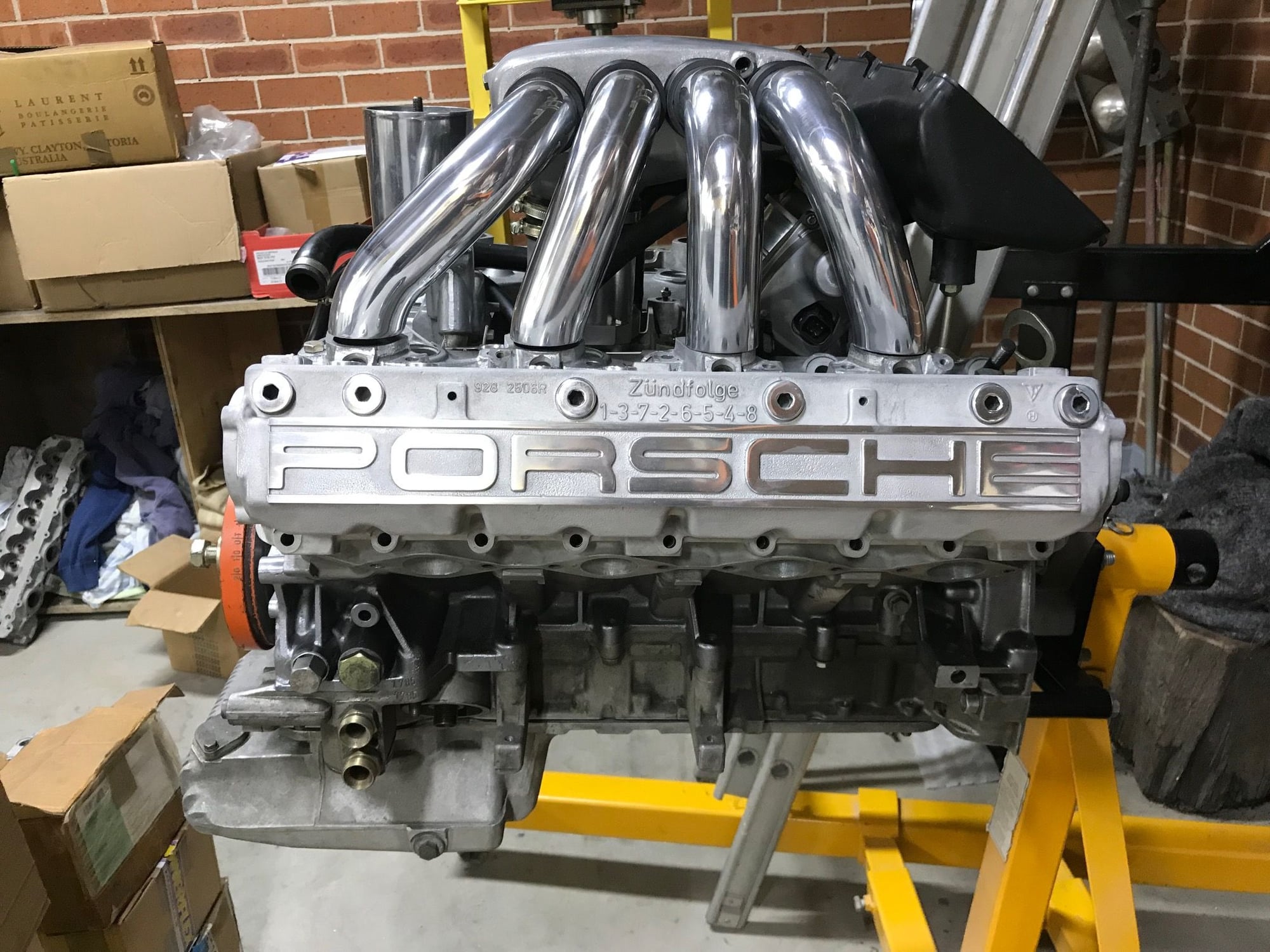
So I’ve stolen some pics and info out of another of my threads (will get a big update soon) the custom manifold thread, the heads being tested are for my 5.35 litre engine for which the custom parts are well progressed. The heads were flowed with my 5.0 litre custom manifold and it was determined we needed a new manifold for the bigger engine. I’m not sure if I’ve ever revealed that manifold, maybe I have? I know a have shown some of the work on the custom plenum. Anyway the pipe diameter is increased and the pipes are straighter as well as a throttle body increase to 90 mm. The reason I’m mentioning this is that the 5.0 litre manifold is perfectly sized for the 5.0 litre heads. The manifold and plenum dropped 10 cfm off the peak headflow. The same manifold and plenum knocked around 30 cfm off the 5.35 litre heads.
5.0 litre manifold on 5.35 litre heads
Headflow numbers at port
Manifold attached
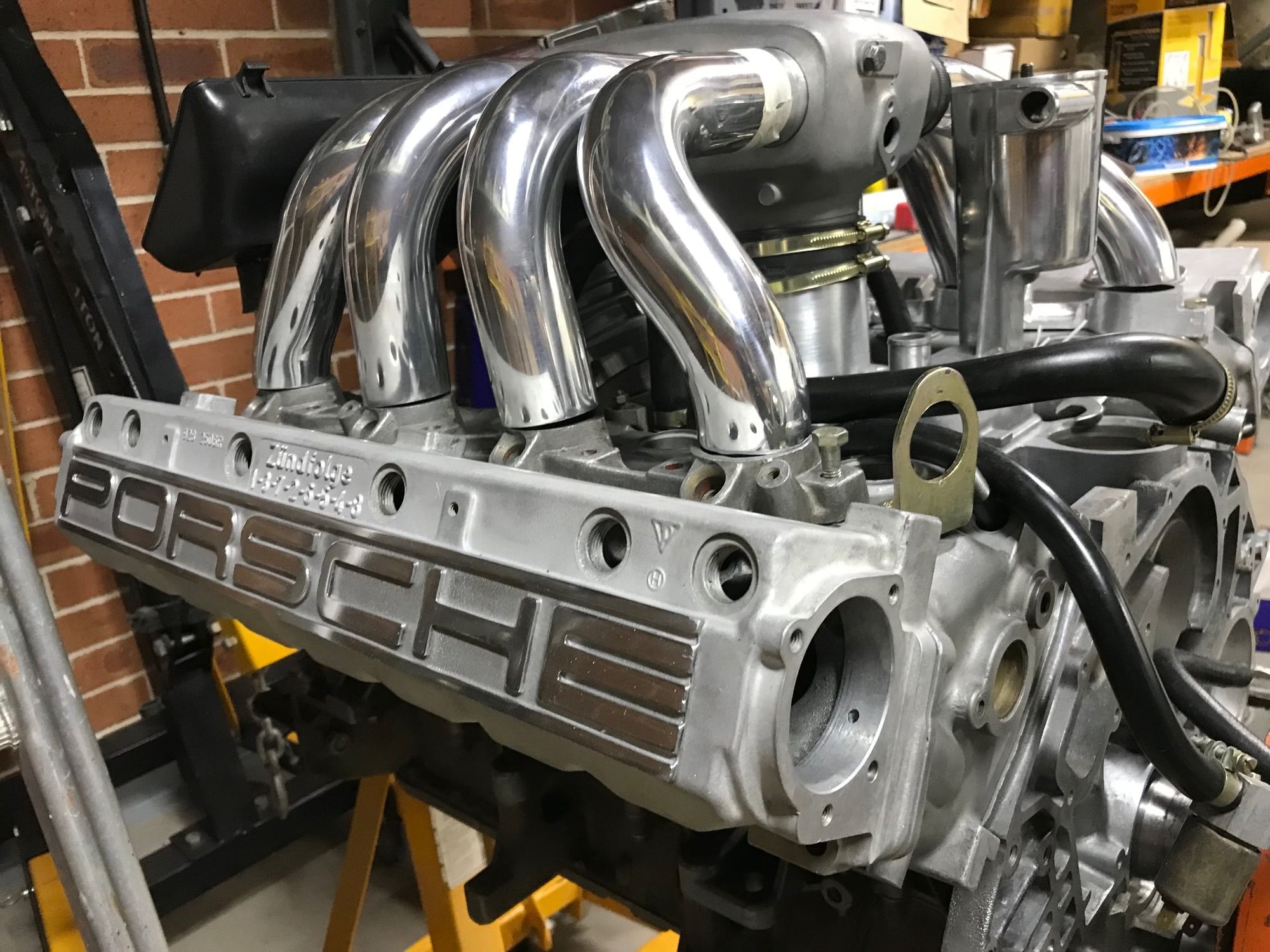
The same manifold which has been tidied up. I couldn’t let it go...
So the reason for the above posting was that if I can make the 5.35 litre manifold flow well where that I’m only losing 10 cfm with it and the plenum attached that means that I will have around 265 cfm less further losses of the throttle body and run to the air filter and of course the air filter too. However a 10 cfm loss for those two key components is pretty good.
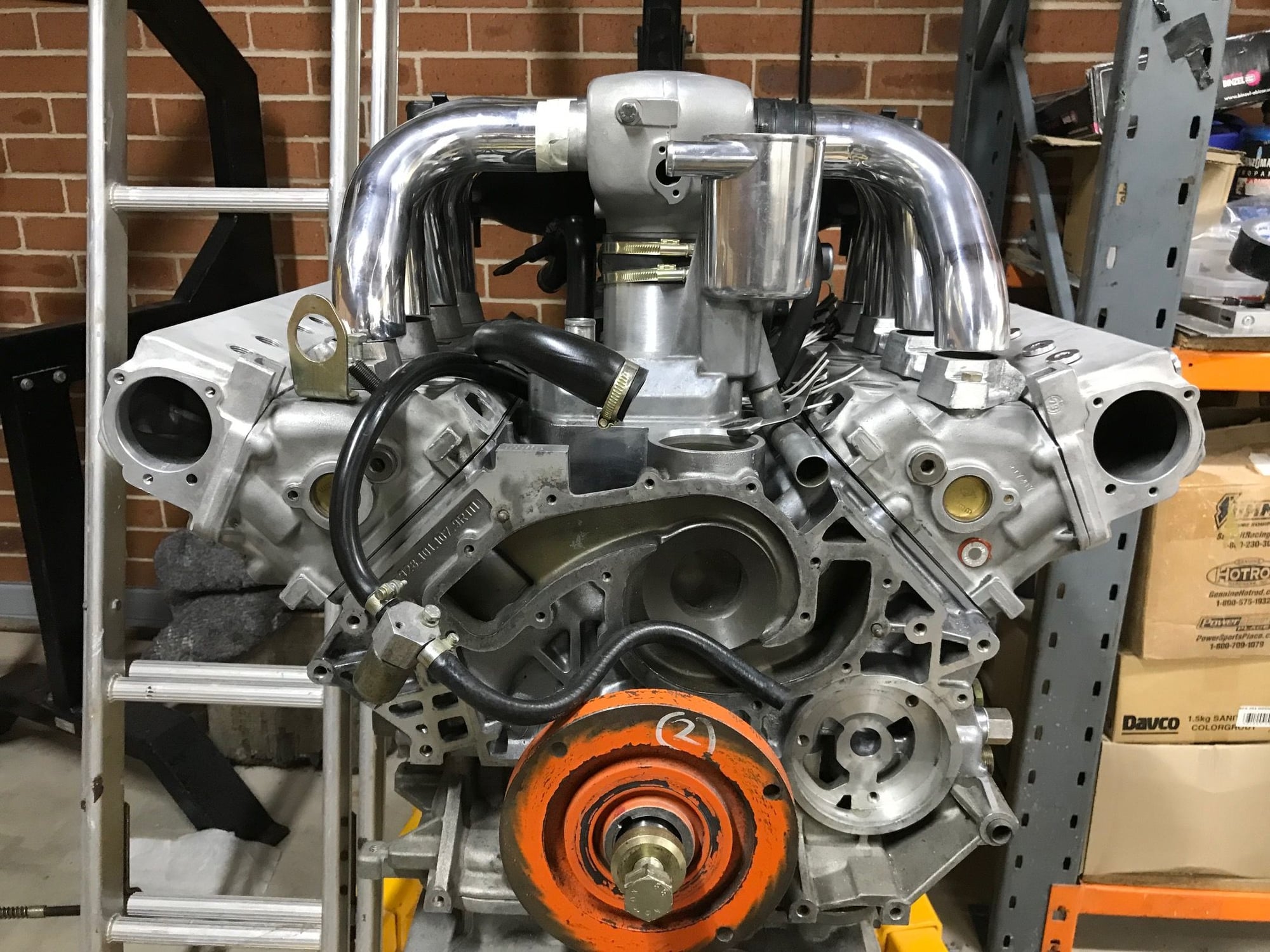
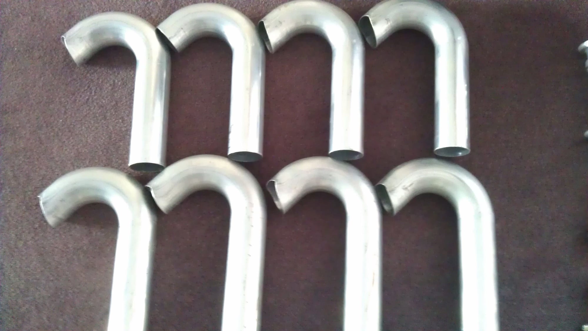
So I have run out of gas and will probably weld the runners to the flange plates this week. It’s not such an easy job either as I must get lots of penetration while not making a mess of the polished runners. The reason for heaps of penetration is that I need to blend the runner to the flange plate so that the transition is nice. It can only be welded from the outside and it would be best if I had the helium mix, we call that alumashield, I only have argon. I may end up paying for this job to be done. So if the new manifold is successful in its application I think I have an excellent chance at pulling off the larger 5.9 litre manifold which is a ITB manifold with tapering runners. I’ll try to dig up an old drawing of the ITB design.
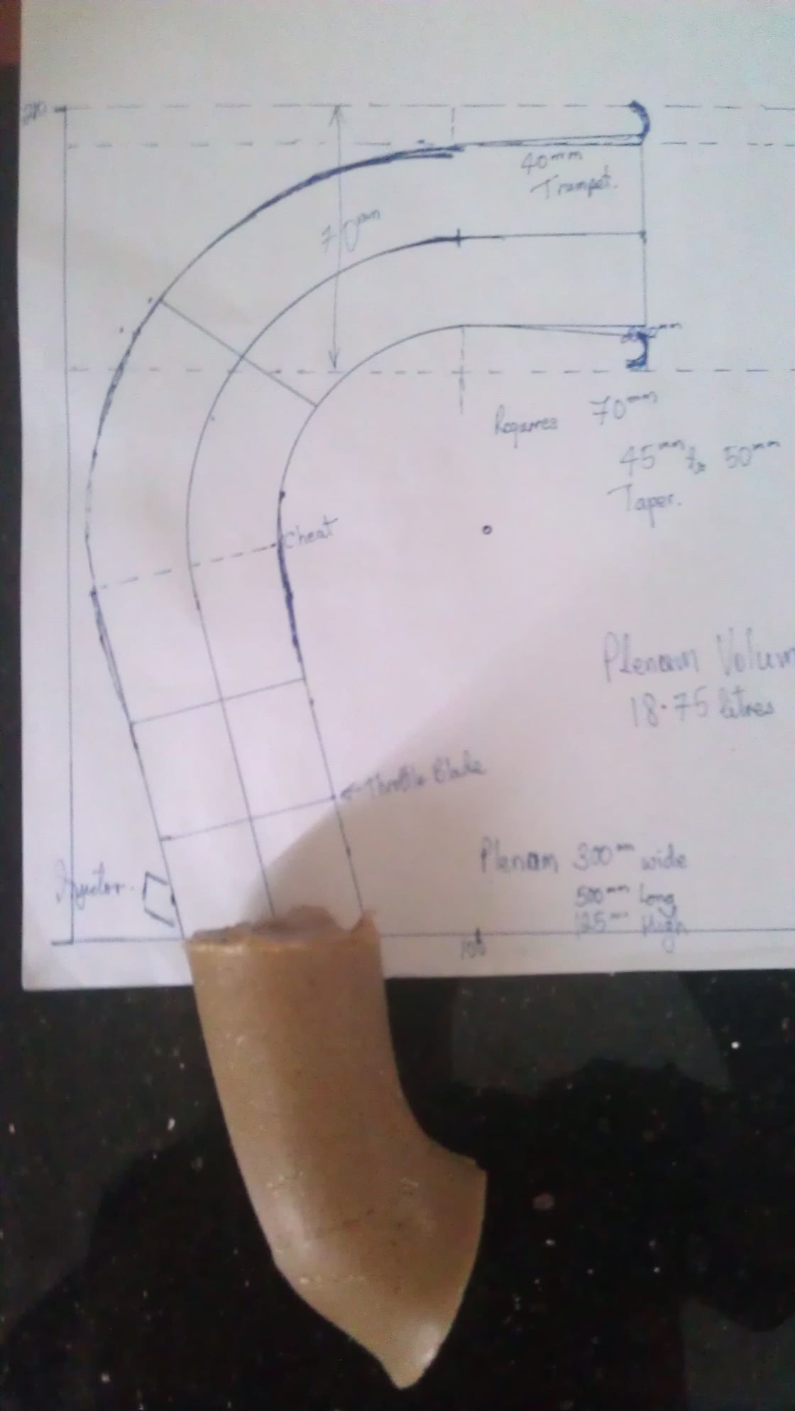
Ok I found some info that relates to the manifold for the 5.9 litre engine. Here’s the drawing first, to explain I want a slight angle for two reasons, it makes the plenum bigger (wider) two it’s a straighter shot to the valve in the high speed section of the intake tract.
The bellmouths are 55 mm and the turn is made at the diameter of 55 mm so the air speed is relatively slow, so losses there should be small. The throttle is 45 mm and shaftless.
Goodfabs in the UK made these for me, this will be the fabricated part of the intake.
He probably will make a plexiglass sump so the jewelry can be viewed from below. Well he is in Australia so everything is upside down - lol.
Ĺke
The reflection on the glass seems to look better than the actual picture.... Raised ribbing polished
‘The photos haven’t turned out that well but the polished ribs look pretty good. This sump is for the 5.35 litre engine but the 5.9 litre will use a fabricated version of the factory sump to keep control of costs.*
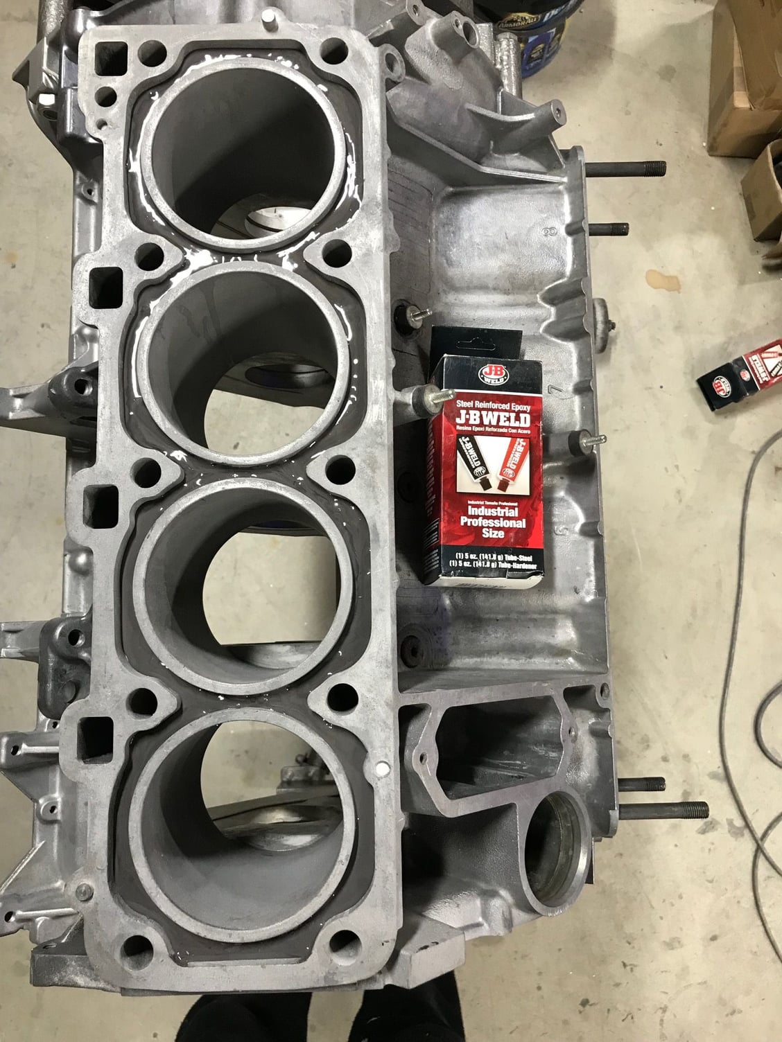
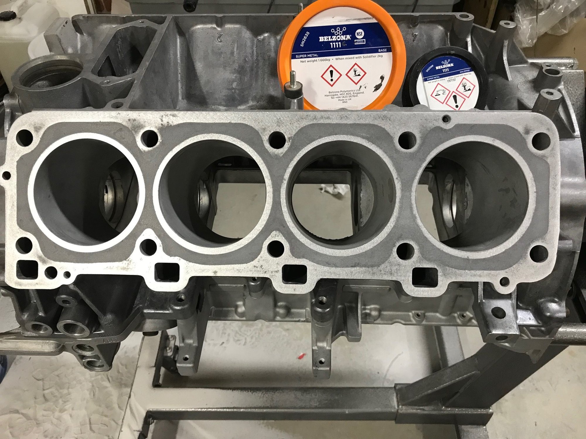
So a long day yesterday finished up at 11.30 pm, the reason was that once I mixed the glue and it was a bit too much. I don’t like waste, worse still a messy and expensive waste. Belzona 1111 is a very expensive liquid metal here in Australia. In fact one kilo is around $300 USD trade. However FYI in the UK where it’s made it’s lots cheaper. It gets very expensive due to the dangerous goods permit required to import. It is extremely strong and is used to repair metal shafts etc.
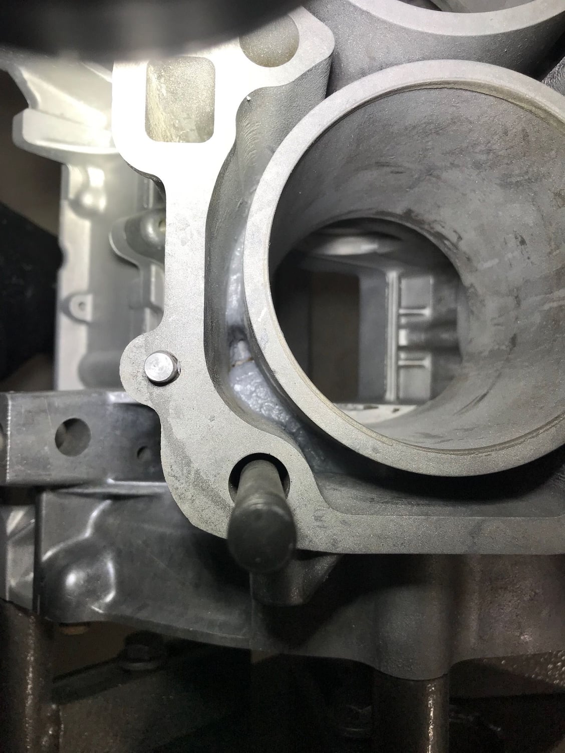
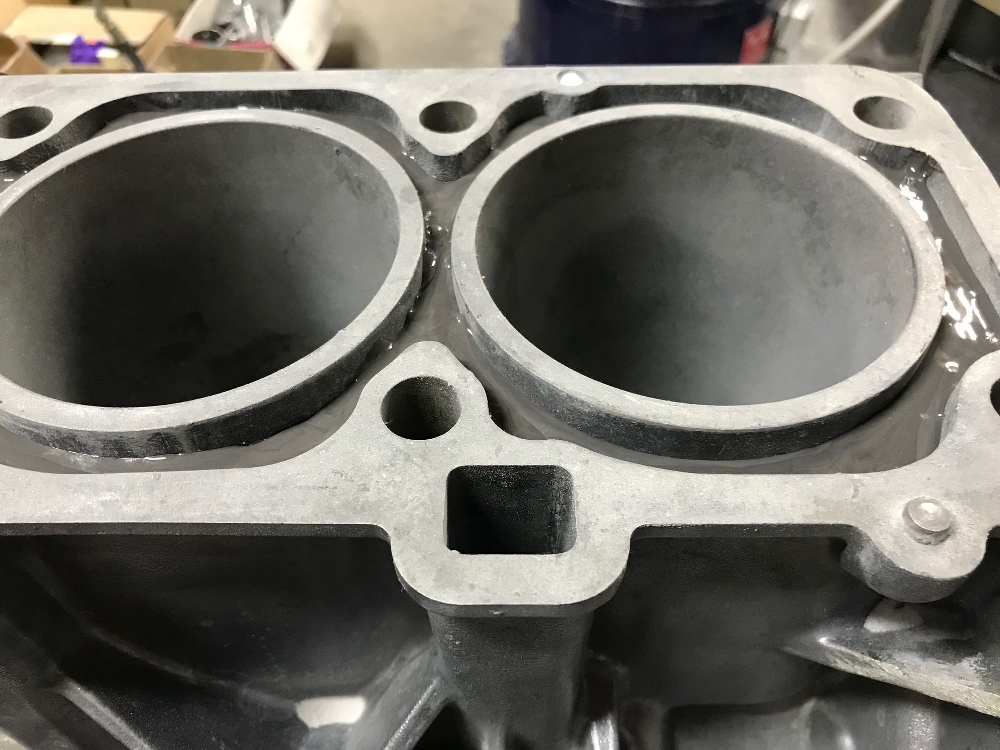
The procedure outlined here is for the purpose of reinforcement as I believe without this reinforcement the block will crack due to thin liners.
The idea here was to fill the block in the lower part of the water jacket and fill it to roughly where the top of the piston will finish which is 83 mm down the jacket/bore. I filled the front cylinders to about 80 mm and the back ones to about 83 mm because the rear cylinders would be hotter and might need a bit more contact area with the coolant. That was filled with Belzona, then I filled the jacket with bicarbonate of soda. As the soda is soft and you cannot pack it down hard. I wasn’t able to apply Belzona directly to it.
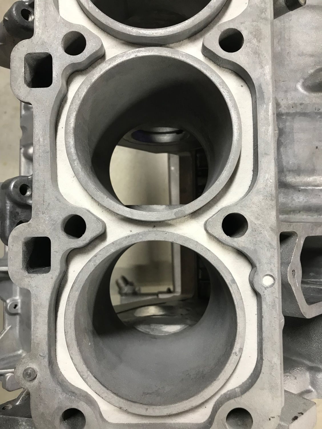
I knew that JB Weld is much more vicous and as such would spread out after lightly depositing it on top of the soda. This worked well. Then I waited till the JB Weld had tacked up and was no longer liquid but still very sticky and then applied the Belzona. This allowed the soda to stay accurately in place. It also will have good adhesion to the Belzona as they are both very sticky. I then waited overnight for the Belzona to harden and then I sanded it. It’s incredibly hard and even with ceramic sandpaper it required three sheets of 40 grit per side to achieve the surface finish required. I’m very happy with the result.
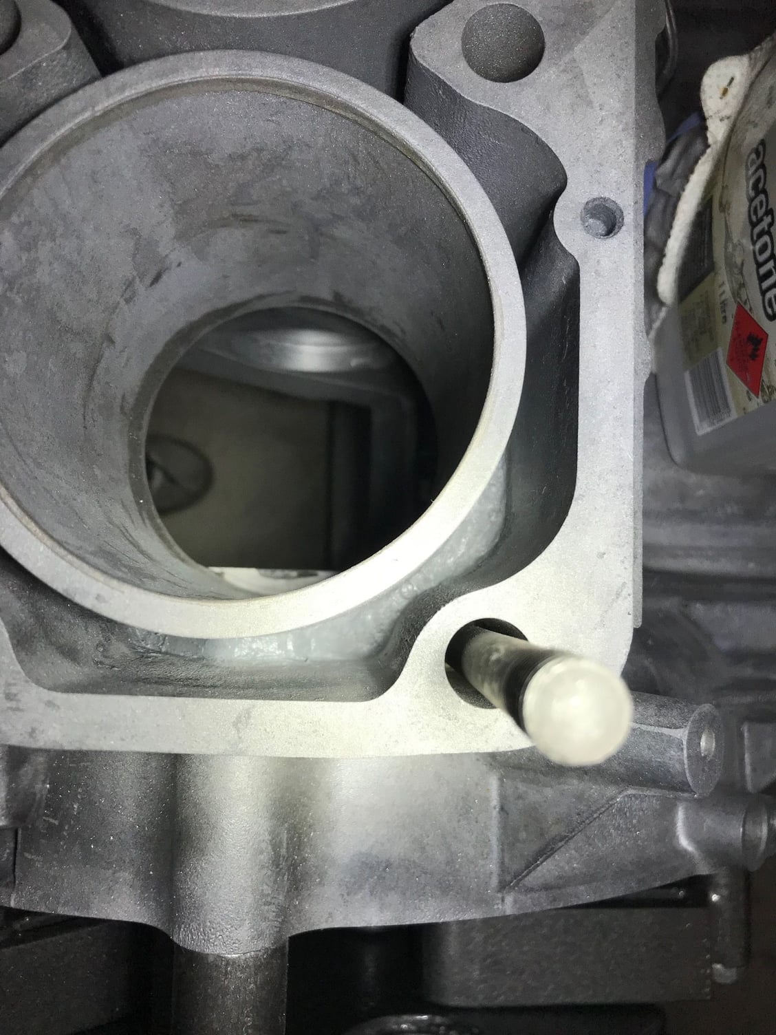
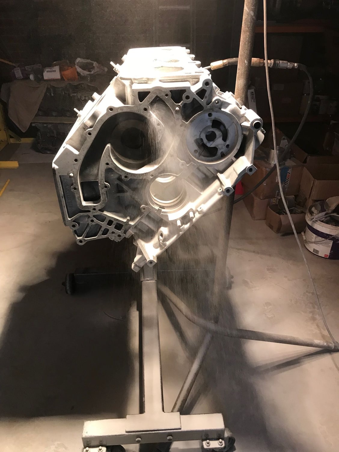
Drain holes preserved
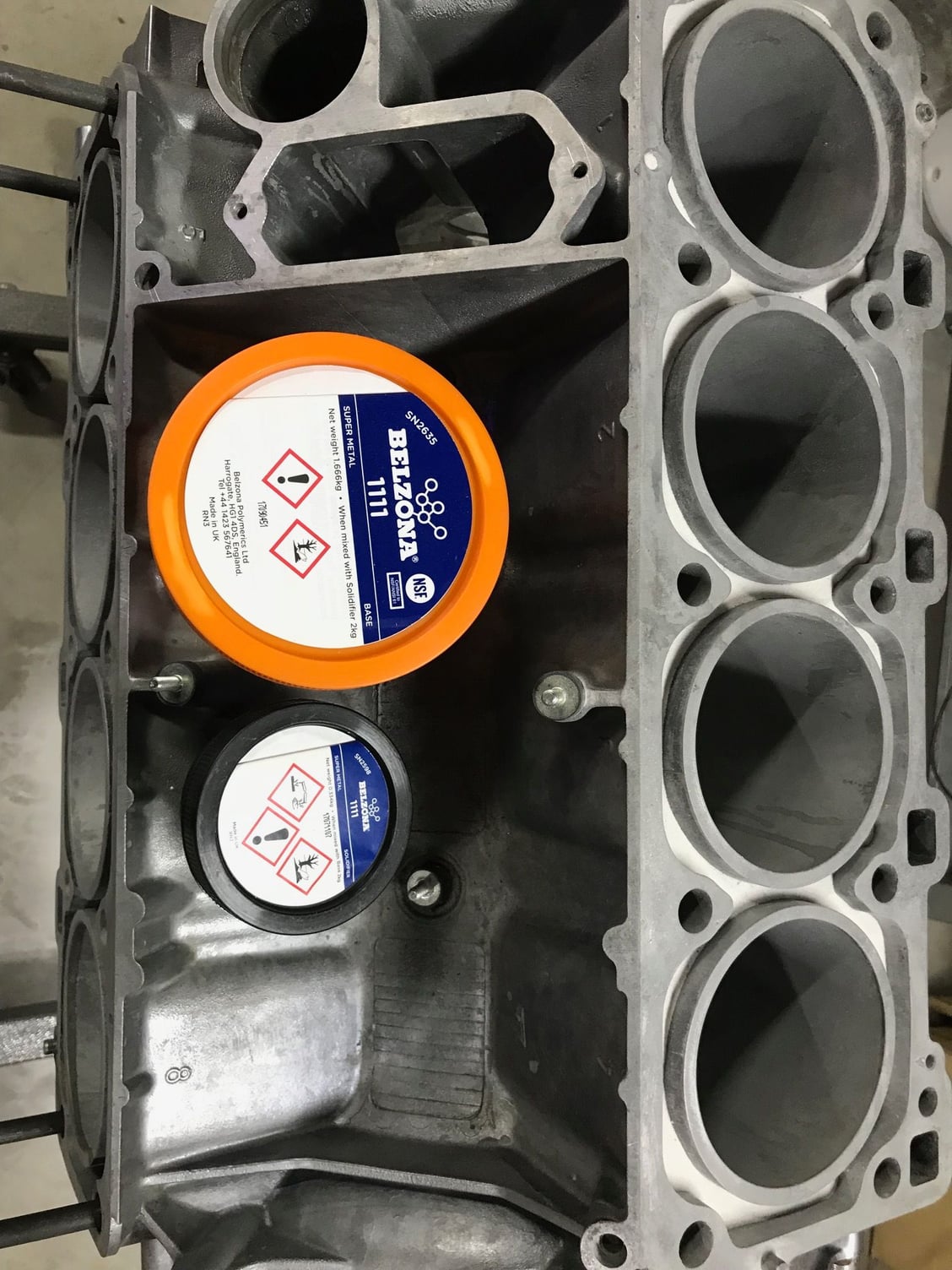
Belzona neatly installed
Filled with bi carbonate showing depth of fill
Overall I used 400 grams of JB Weld and 2600 grams of Belzona
Greg, how will the cylinders be cooled with their water-jackets filled in?
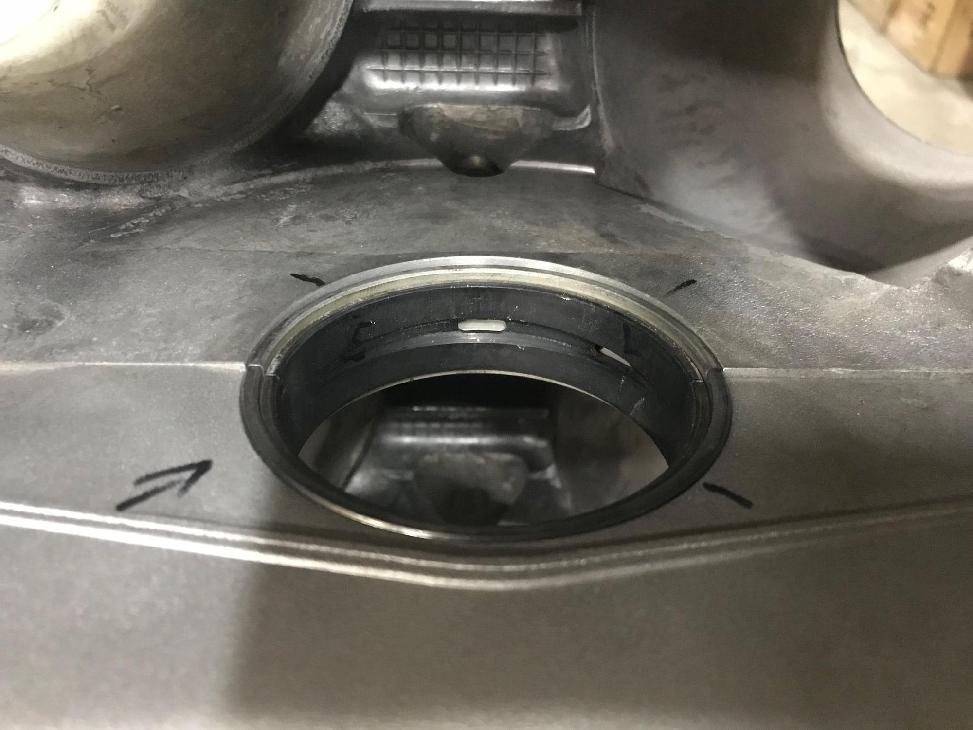
The water jackets are partially filled, basically I’ve filled the bottom of the jacket in to roughly where Porsche cast the 968 block. You can see via the two photos showing the drain plug still usable and the other photo Neat install of Belzona. Then the top of the block is now closed like the vast majority of engines made today. So there is still around 65 mm of depth to the water jacket. Remember also the cylinder heads also do a lot of cooling. I don’t know the absolute effect of this however another consideration is that the water pump is still pumping the same amount of water and the space in the block is smaller so the water will travel past it quicker. I’d imagine if the temperature delta increases at the liner the increased water flow will assist in controlling this. It’s not unusual to have performance engines block filled. The Ford Cleveland is a favourite for that when using the factory block.
I still need to drill the holes for the head gasket, this is for the transfer of water between the block and heads.
Last edited by slate blue; 08-30-2018 at 02:29 AM.
Reason: Extra details
Greg, did you sand the top of the block by hand? Are you going to machine the top surface? Well, I suppose if the hand sanding is properly done with a flat block and emery cloth it will be OK.
Ĺke
Greg, did you sand the top of the block by hand? Are you going to machine the top surface? Well, I suppose if the hand sanding is properly done with a flat block and emery cloth it will be OK.
Ĺke
No Ake, the deck will be machined but after the liners are installed, I also need to drill out the ends of the deck of the block for water transfer.*Remember I am doing the reinforcement now because we need to bore out the liners further and they will get thin around 3 to 3.5 mm thin. So they need support before cutting them down. Then the other consideration is*my liners have flanged tops, so all off the tops of the factory liners will be gone as such the Belzona will offer support. I will put fresh Belzona around the flanged tops to further inhibit any rotation of the liner. I am not going to use much interference probably around 0.0015”.*
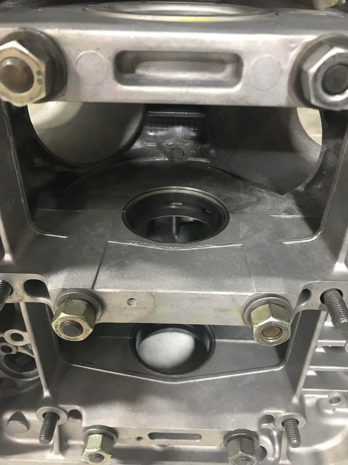
Well crappola of a day yesterday for which I will spare you all but I did spend some time modifying the block and bearings. This in it self wasn’t so hard but when I fitted then up and measured the clearances it was not the best. Some that if not all of that problem comes from the inadequate way fix align the top and bottom sections of the block. What I did was modify a hollow dowel and fitted that to the front of the block. So now in theory we have two dowels that will align the block accurately.
Well it’s never something you should take for granted. The manual says use the oil pump at the front and maybe the oil seal at the rear? To assist the process. I am not disputing that but the way the Chevy LS engine aligns it’s caps is better. So when there is no crank fitted you have the luxury of being able to check how well it’s all fitting up from the bearing clearances. Lucky I have a rubber hammer is all I will say. At its worst I had 0.07 mm at of round. That is on the X measurement that is how much difference there was. I have now reduced that to around 0.02 mm and I will go with that I I know for fact that factory assembled engines have been worse. Not sure on the mains clearance yet but thinking around 0.002”
Greg, for aligning the lower girdle to the crankcase, at the rear it is a dowel pin and at the front the main bearing bushing. Older engines did not have the front main bushing but a split front main bearing. The older engines have a dowel pin both at the front and at the rear. I suppose it would be possible to use the oil pump bore for alignment. A ring having the proper fit inside the oil pump bore has to be fabricated, think the fit of the oil pump housing itself is too loose. Main bearing oil clearance of 0,05 to 0,08 mm will be good. Page 16: https://www.mahle-aftermarket.com/media/local-media-north-america/pdfs-&-thumbnails/catalogs-and-literature/engine-bearings/eb-40-14.pdf
Ĺke
Great Mahle document - thanks Ake (I had to google the filename as clicking the link didn't work for me). Lots of good pictures and explanation of wear marks etc.
Weird, link doesn't work anymore (possibly as I have my browser set to remove cookies when I leave a site). Googling for "eb-40-14.pdf bearings" is how I got the document.

 08-25-2018, 04:02 AM