When you click on links to various merchants on this site and make a purchase, this can result in this site earning a commission. Affiliate programs and affiliations include, but are not limited to, the eBay Partner Network.
Hi friends. I’m looking for your expert electrical help here, as when I was inspecting my TB sensor connector, it came off the wire. (FYI - TB is in correct tension and in good shape.)
it happened before, but I guess I didn’t do a great soldering job, as it came off again. Knowing that these connectors are NLA, I would love to get your suggestions on how to repair properly, even though I am a novice at this.
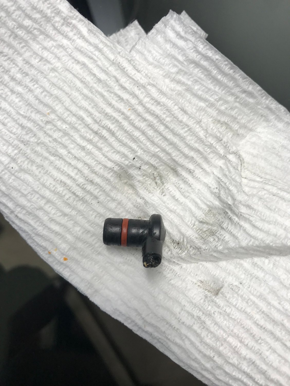
any suggestions on how to address? Here is a pic of the connector head.
I've cut back the plastic on one and exposed enough wire to solder a pig tail on then heat shrink it, then slide heat shrink over the wire and solder the pig tail to the actual wire harness.
Thanks for the suggestion, as I was thinking that was the probably the best approach as well, as long as I can get enough wire out of what is left of the connector neck.
Do you happen to know he gauge of wire you used for the pigtail? 12 or 14?
Just buy a new one if your time is worth anything at all to you. You can screw around and solder this again and again or you can replace it and be done with it.
Yes. When Sean Ratts fabricated the front of engine 14-pin harness for me, he said that connector was NLA. I have to rig something up. Have not yet done so.
Yes. When Sean Ratts fabricated the front of engine 14-pin harness for me, he said that connector was NLA. I have to rig something up. Have not yet done so.
He would know.
How about 3D printing some with a pigtail? Would that be possible? Add the O ring and go?
In the interim, Skpyle, you could remove the part with the grommet that attaches to the center timing belt cover and simply remove that part in lieu of a simple spade connector if you absolutely had to have timing belt warning capabilities. When the 3D printed parts arrive, that setup would be easily reversible.
When I started these back in 2014 there were a couple hundred of those connectors in stock at Porsche. As soon as Roger posted a thread about them "someone" bought up all the stock and we've been trying to get Porsche to make them again. I hope "whoever" did it gets stuck with all of the ones they bought.
In the interim, Skpyle, you could remove the part with the grommet that attaches to the center timing belt cover and simply remove that part in lieu of a simple spade connector if you absolutely had to have timing belt warning capabilities. When the 3D printed parts arrive, that setup would be easily reversible.
That is more or less my plan. I will try to make it reasonably sturdy if not elegant.
Thanks!
When I started these back in 2014 there were a couple hundred of those connectors in stock at Porsche. As soon as Roger posted a thread about them "someone" bought up all the stock and we've been trying to get Porsche to make them again. I hope "whoever" did it gets stuck with all of the ones they bought.
So plan A was to trim the neck of the plug to expose the wire, then solder a short wire to it to create the pigtail, then connect it to the original wire. I was surprisingly successful in trimming the neck at the round base, where it popped off, exposing the wire with black insulation. However, that was the end of the good news. when I started to attempt to strip the wire, I noticed that it rotated freely in the plug, then pulled right out of it. Something happened at some point where the wire deteriorated and lost connection inside the plug with the terminal. Now it makes sense how the thing kept sending warnings!
So off to plan B, and your suggestions helped me. I plan on removing the internal sensor wire from the grounding tab inside the the TB cover to the cover itself (have to adjust the tab anyway, and replace it with a female spade connector to 14 gauge wire that will go through the hole in the tb cover to another female spade connector. I'll then solder a short piece of 14 gauge wire to the main sensor wire outside of the cover and put a male spade connector on the end, and will connect the male and female outside the TB cover to simulate the plug. I think the only thing I need is a rubber grommet of some kind to seal off the wire opening in the TB cover.


 05-20-2018, 06:09 PM