When you click on links to various merchants on this site and make a purchase, this can result in this site earning a commission. Affiliate programs and affiliations include, but are not limited to, the eBay Partner Network.
Well, THIS is proving difficult! My L-jet harness has the double layer fingers, exactly as Seth shows in his first post. After literally two hours of fiddling I was able to get both wires out of ONE connector. And no damage or bending. But I've spent another two hours on the next connector and just can't get the pins out at all. I have not one but two different cheap key removal tool sets!!
I think this is the problem: the little, non-folding tabs on the BOTTOM side of the pins (opposite side from the tab we're trying to depress). Those little tabs are at about 90 degrees to the body of the pin. And the problem seems to be that when you insert the key to depress the folding tab on top, you're compressing the bottom-side pins into the somewhat soft plastic body of the connector -- thus immobilizing the pin.
On the two pins I've been able to remove so far, both left a lot of scratches on the bottom side where those 90 degree tabs dug into the plastic. I've tried cutting narrow strips from a soda can to slide underneath those bottom pins but that's fiddly too and so far hasn't really worked.
I've tried two or three different removal keys, and the one that worked for me is the correct height for the slot on top but is sharpened to a point on one side. I put the pointy side against the pin and the curved side against the plastic body. It LOOKS like it should be perfect but this is turning into a huge pain and I will have to abandon the idea of putting on the new-style connector bodies unless I can get the pins out more easily!
Anybody BTDT and can tell me what I'm doing wrong?
OK, figured it out. I finally used an X-acto saw and just cut off the back part of each connector (right at the junction where the narrow part in the back, that the rubber boot attaches to, meets the main body of the connector). If you saw as close as possible to the main body of the connector, you'll saw just where the bend-up tab meets the back of the channel that keeps it in place -- allowing the pins to finally come out without any drama. You just have to be careful to not saw into the pins -- but just go slow and careful and it's not hard.
So on the bottom channel (where the "top" channel holds the bendable tab), there is a small bump molded in just behind the small tabs on the bottom of the pin. This basically makes the pins next to impossible to remove using the bending tab alone. Perhaps a special knife would work from the back to lop off that bump. (There's no access to the bottom channel from the front of the connector, and even if there was, you'd hit the 90 degree tab which seems very difficult to bend). I wonder if my two hours of fiddling basically wore off the bumps on my first connector (all I saw were scratches left behind). Or it's possible they were removed at the factory because I started with the oddball 9th connector that hooks up to a temp sensor, and uses thicker gauge wires than all the injectors, and perhaps with the thicker gauge they removed the bump. In any event I confirm that there's clearly a molded in bump on the 8 injector connectors. In fact, to remove the pins from the sawn off back half of the connector, I still have to cut off the bump, but now it's easy as it's just behind where I made my cut. What a pain!
Edit: I should also mention that these bumps in the bottom channel correspond to two melted-in indentations made on the outside of the connector. I suspect that the pins were pushed in at the factory, then a pair of heated prongs were used to melt and push in the plastic slightly, thereby creating these internal bumps.
But the nice part is that now I can slide on the new easily-removable connectors onto the existing pins, yay!
I have just read your post and your reply, and am making note of this. When I disassembled my fuel injection harness a year or so ago, it was a b*tch getting those pins out. This was before I made this post here. So, I am going to make note of what you have done when I go back to finish the harness.
Thank YOU, Seth! If not for your original post I wouldn't have even thought to do the upgrade, or even have known such a thing was possible. I made some edits above too about the melted indentations. I'll post some pics later!
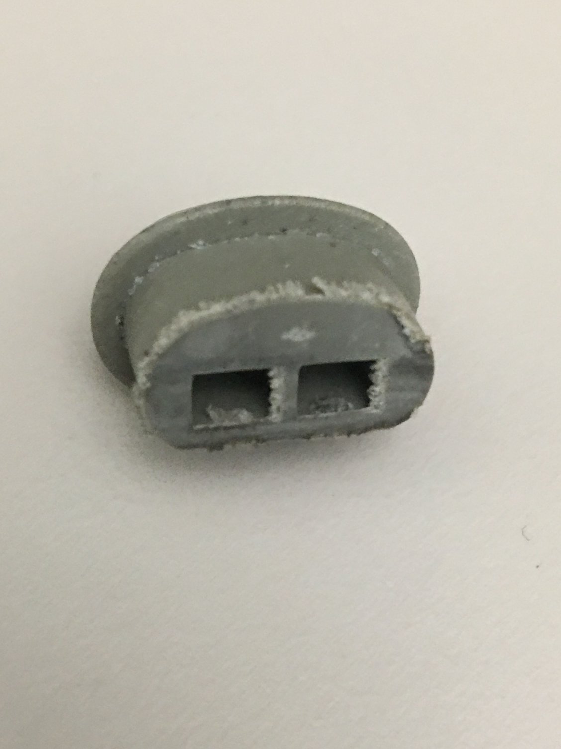
Here are a couple of shots showing the internal bumps and external melt marks. They REALLY don�t want these pins to EVER come out! Again, I first sawed off the main body of the connector. I then had to carefully use an X-acto knife to remove all traces of the bumps and all flashing (from the X-acto saw) from the corners of the pin channels or else the pins won�t come out.
Seth, that's because I had an unused SPARE harness! Now that I have the new style connectors on it, I'll be swapping it in as part of my refurb project (https://rennlist.com/forums/928-foru...oses-83-a.html). Once I get the old harness out (which is in very good condition considering its age) I'll be putting on the better "double layer" pins, new boots and the upgraded connectors. Interestingly, the old harness is a pale pink color, as is my main engine wiring harness, and has only the single-layer style pins. Is the gray color newer or older I wonder?
By the way, for "fun", I tried to remove one of the double-layer pins from the upgraded connector with the key tools and couldn't get it out. But I tested some of the single-layer pins (that came with the new connectors and boots) and they are super easy to remove, sigh. But those single-layer pins are highly inferior in my opinion. Not only would they appear to have inferior physical connection properties, but they are of a different and simpler design where the main body is a simple folded box shape (actually quite different than these double-layer pins). The simpler pin is super easy to deform and is much more fragile.
One more note, just in case this might help somebody some day. Through this project I have learned WAY more than I ever wanted to know about these stupid pins, and the construction of the L-jet wiring harness. As part of testing the continuity of each of the injector wires (and ensuring that I had the positive wire on the "correct" side, see more below), I mapped out where each wire goes. Fun fact: I had always assumed that all the injector wires went through the giant L-jet connector. Not so -- it is only the negative wires! Of course, that makes perfect sense, because the L-jet control unit fires the injectors by switching them to ground.
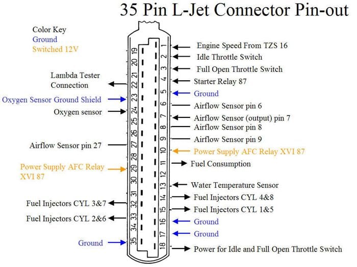
FYI, as has been documented many times, on the big L-jet connector, the mapping of pins to cylinders is: pin 14 for cylinders 4/8, 15 for 1/5, 32 for 3/7, and 33 for 2/6. See attached diagram. These are the grounds not the positives!
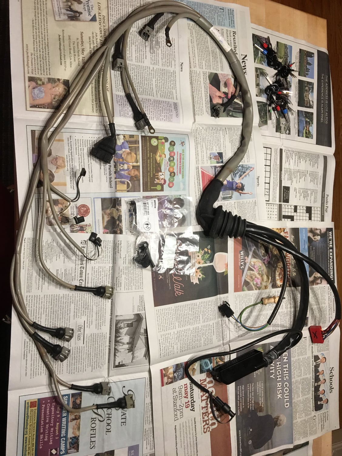
So where are the positive leads routed? To pins 2 and 3 on the separate red block connector, see below, marked "X". Cylinders 1/2/5/6 go to the pin labeled 2 on the connector itself, and 3/4/7/8 go to pin 3.
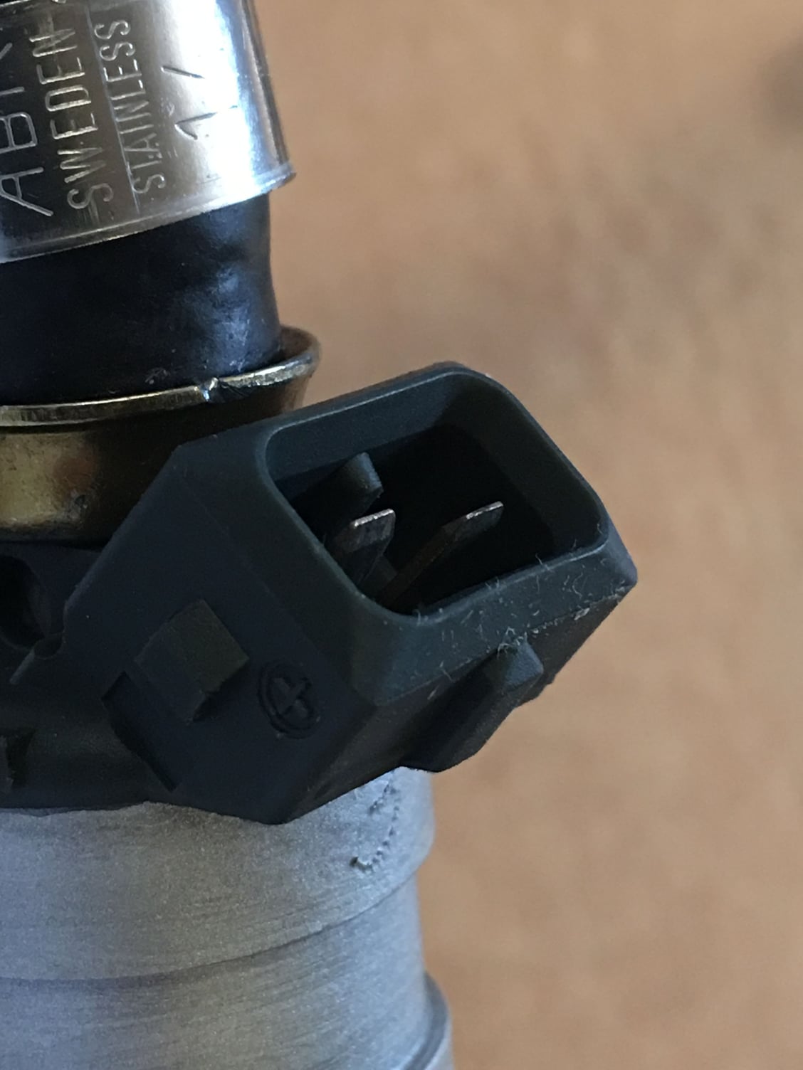
By the way, I did some searching about whether it matters which lead at the injector is positive or negative. The clear consensus here on Rennlist is that it doesn't because a solenoid works either way (I assume that's because metal is attracted to both the north and south poles of an electromagnet, so switching polarity still works). However, I ensured that all the positive leads run to the "+" labeled on the injector, which is the left side pin on the injector itself when you look at it as oriented in the car (fuel input oriented up, connector facing you).
Hard to see, but there's a "+" symbol next to the left pin. (And yes I'll be straightening that pin out, the pins all came back bent from the cleaning service)
if you're ever in a pinch without tools but have some more time, you can use a regular plastic push pin to de-pin the connectors.
1) from the back of the connector push the wire IN (like you would if you were installing a new wire into a new connector)
2) from the front of the connector use the push-pin to hold down the "tang"
3) while keeping the push-pin in place, pull the wire out the back of the connector.
takes a few tries but easy once you get the feel for it.
I thought we were into high quality German tools around here.
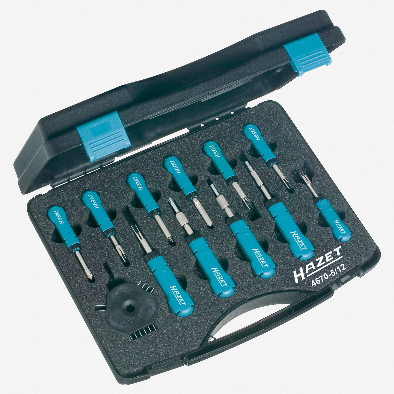
How about the Hazet 4670-5/12 release tool set? It does cost just a little bit more, though. OK, it actually crosses over well into the mucho dinero territory.
Lol!! I don�t care HOW much it costs, it will not get the pins out of the grey connectors with melted in bumps!! A $10 X-acto saw works great though!! 😇


 02-20-2019, 05:39 PM


 OK, it actually crosses over well into the mucho dinero territory.