When you click on links to various merchants on this site and make a purchase, this can result in this site earning a commission. Affiliate programs and affiliations include, but are not limited to, the eBay Partner Network.
I have some AT89S51, changing the crystal implies hacking the F9T board... :-( Will not do this... I have old ECU and KLR that are still working, I can play around with those for sure.
I think I lost/cannot find the KLR eeprom... I you have one, can you please PM me the .bin file ? I have a bunch of eeprom on my desk and none of them have the appropriate code/table...
I was looking at there tools, wow, the cost of this is way over my budget for this; the pico technology stuff. I have a very nice scope 4 channel and 16 digital reader... I think I have enough stuff as of now(I have a common health problem called Workshop Induced Finance Exhaustion or WIFE ;-) )
Cheers,
Charles
I can try to copy the 24pin program from the KLR, but I have not had a lot of luck doing this with my chip burner. Do you need the Turbo or Turbo S KLR program?
I can try to copy the 24pin program from the KLR, but I have not had a lot of luck doing this with my chip burner. Do you need the Turbo or Turbo S KLR program?
-Joe
Turbo.
My 2nd KLR is, well FD 455. That's what is writen on the digital board...
I'm also looking on the equivalence on the pressure sensor, I found Honeywell sensors that are very accurate but quite expensive...
I.E: HSCDRNN030PAAA3 Pressure Sensor 30PSI (206.84kPa) Absolute Male - 0.08" (1.93mm) Tube 0.33 V ~ 2.97 V 8-DIP (0.524", 13.30mm), Side Port
55 CAD... with Digikey .
I'm doing this to see if LR MAP sensor is as accurate as I need it to be. You told me in tha past the LR external code does not interpret the MAP value correctly... Just debugging...
I use GQ-4x4 as an EEPROM/MC extract and program tool. Very nice but you need extra adapters depending on the chips...
Charles
Last edited by riouxc; 03-22-2021 at 12:34 PM.
Reason: Adding info
Hi Joe
Thank you again for supporting our platform. I'm really interested in the SS fan relay and wondering how the LED side worked on your prototype. I really like the idea of the buttons to test.
I'd love to help with Beta testing of it(I did that on SS DME relay) or getting a retail version when available. Do you have a timeline?
Bruce
Hi Bruce,
What I hope will be the finale production version of the Solid-State Fan Relay should arrive early April. I will have a limited quantity of them on hand, after that there will be around a 6 week lead time for more units. I originally put the LEDs and buttons in for development, but it was immeadilty obvious their value in diagnosing all issues with the cooling fan system. The LEDs "Temp Slow" and "Temp Fast" are wired directly to the fan switch in the radiator. The fan switch grounds these inputs to activate the fans, so if the LED is illuminated, then the fan switch is commanding the fans on. It should never be the case that the "Temp Fast" LED is on and the "Temp Slow" LED is off. This is an immediate indicator there is something wrong with the fan switch. The momentary buttons just ground the same pins as the temp switch, so they can be used to instantly verify everything be between the relay and fans are good. Also, unlike the factory relay, each fan is isolated on its own fuse. This makes sure you don't lose both cooling fans if one of them fails in a way that draws too much current. It is also worth noting that the large transistor looking devices in the picture are purpose-build automotive grade drivers made specifically for high-current inductive loads like cooling fans.
I have a broken pin in a scocket... Anyone knows how to get this out without damage ???
Thanks,
Charles
From the picture it doesn't look like the stuck pin is sticking out far enough to remove it directly with a tool. If this is the case, then it is best to send it back to me so I can replace the socket.
From the picture it doesn't look like the stuck pin is sticking out far enough to remove it directly with a tool. If this is the case, then it is best to send it back to me so I can replace the socket.
- Joe
Thanks,
But, first, I will try Uncle Bill's Sliver Gripper Tweezers Survival. I will also try my wife's tweezer ( never know untill you try...)
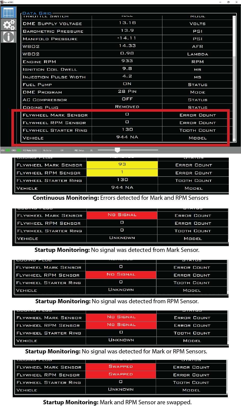
I just released a big update to the website. The automated flywheel Sensor diagnostics is now a part of the FocusOBD software! This feature can diagnose a failed flywheel sensor in seconds just by cranking the engine. It also continuously monitors both flywheel sensors and increments an error count if a mistake is detected. If you have intermittent issues due to bad wiring, you can simply jiggle the sensor wires while the engine is running and see if either sensor error count increments.
This feature is still in Beta as some work still needs to be done, but it is more than 85% complete. At this point, I could use some feedback. Also, this feature will not work on the Beta OBD+ module. If you have the Beta OBD+ module, you will need to send your SPORT DME in for a free upgrade. If you do not know what module you have, you can check by downloading the latest FocusOBD software, then verify under Setting Tab->OBD Interface->Firmware Compatibility. You need at least revision B.
On a 944 with good signal on both sensors, the error counts should always be zero, and the flywheel starter ring tooth count should be 130 for NA or 132 for Turbo. You should also see that the software detects your vehicle as “944 NA” or “944 Turbo.” If you are seeing error counts, please enable the logging under “Settings Tab->Logging->Flywheel Sensors” and let the system capture error events. You can then send me the log file located in “C:\logs.” It should be the newest file in the directory, but if you are unsure, you can send me all the log files. Also, make sure to disable the logging when you are done, or the log file will be overwhelmed with flywheel sensor entries.
If you want to take testing a step further, you can disconnect the flywheel sensor(s) and see if the simulated fail is detected by the OBD+ module. However, be aware that the electrical connectors can be brittle with age and could break.
Note: When turning off the ignition to reset the startup diagnostics test, wait 4 full seconds before switching the ignition on then wait 4 more full seconds for the test to setup before cranking. This is a workaround, I am looking into a permanent fix for this issue.
Here are screen captures of the different signal failures the OBD+ module detected on my 944 NA from testing this morning:
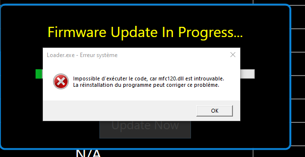
I have an issue with the firmware upgrade.
Windows 10 Pro. The loader cannot find mfc120dll file
I reinstalled and I have the same issue.
Thanks,
Charles
Hi Charles,
Have you tried install/reinstall the Microsoft Visual C++ 2013 Redistributable (x86)? You can download the correct package on the FocusOBD download page. The firmware updater is dependent on mfc120.dll, this file must be located in "C:\Windows\SysWOW64". You can manually copy this file into this directory if the installer fails to do it for you.
Have you tried install/reinstall the Microsoft Visual C++ 2013 Redistributable (x86)? You can download the correct package on the FocusOBD download page. The firmware updater is dependent on mfc120.dll, this file must be located in "C:\Windows\SysWOW64". You can manually copy this file into this directory if the installer fails to do it for you.

 03-20-2021, 12:31 PM