DME - 2 resistors burned, anyone got schematic?
 06-04-2009, 07:12 PM
#1
Advanced
Thread Starter

Join Date: Dec 2003
Location: Finland
Posts: 52
Likes: 0
Received 0 Likes
on
0 Posts
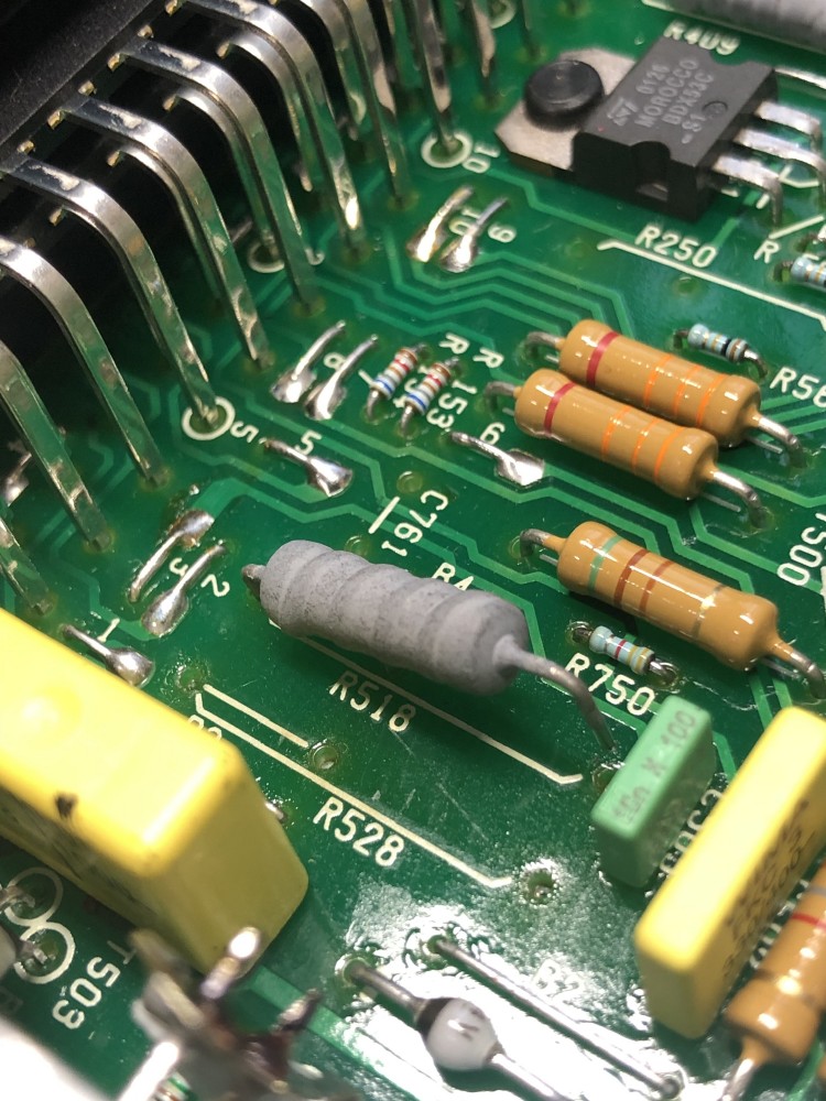
Short version: Look at attached pic, what are the two grey resistor values? Or maybe someone has full schematic? Car is '86 N/A.
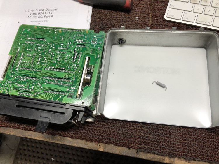
Longer version: Old problem returned, car is running bad when it's raining, and it's a problem of fuel delivery. DME relay is clicking all the time, the higher revs the faster it clicks. When relay is replaced with a jumper the car runs fine. And I've tried 2 relays, it's not that. Further investigation showed that voltage between relay pins 87 and 85b isn't constant, but keeps disappearing in sync with engine, which cuts the power from the fuel pump at the same rate. both 87 and 85b go to the DME box, so out of desperation I took it apart to look for cold joints and found what you can see on the attached picture. I don't even know if it's related, but I guess I want to fix it anyway
I've found links to FR Wilk's old site with supposedly schematics of motoronic, but the links are dead, and I can't find anything like that on the new page. If anyone has those schematics it would help greatly.
 06-04-2009, 08:09 PM
#2
Race Car
I am no electrical engineer but often a component fail when something else cause it to fail. I would be surprised if replacing 2 resisters will fix that problem.
06-04-2009, 08:26 PM
#3
Three Wheelin'
Considering that the relay clicks with the RPMs, have you checked the wiring and the connections between the DME and relay socket? I recently had an "I'm a dumb ****" moment with a mower that would only fire on 1 of 2 cylinders under load. Turned out to be a bad connection (crushed wire grounding at times) that was only bad with engine vibration under load, and exactly followed the RPMs.
...not at all saying you don't need a fix (and/or replacement) DME, but that might not actually be your root cause here. I don't see how scorched resistors on their own can cause that. It would be more likely that if they were bad it would be a hard failure. I've seen worse looking semiconductors still doing their jobs.
Best case, maybe someone has a junk DME that doesn't have that particular section all torn up that you can buy and replace the components (or convince them to pull and meter).
Last edited by DarylJ; 06-04-2009 at 08:27 PM. Reason: Edit: "but I did used to do board level repair guy"? Nice.
06-04-2009, 08:38 PM
#4
Nordschleife Master
No need to worry, just install 2 power resistors, or install larger resistors, they really only act like fuses anyway.... OR just install solid wires in place of teh resistors...
M Ampere is rolling over right now... and I can hear my lightning bolt being generated just for me...
06-04-2009, 09:19 PM
#5
Addict
Rennlist Member
Rennlist Member

Join Date: Feb 2002
Posts: 5,384
Likes: 0
Received 0 Likes
on
0 Posts
That burned up resistor goes to the driver transistors on the heat sink. I would guess that the transistor is also blown. Link to schematics below:
http://www.the944.com/ml31dwg.htm
http://www.the944.com/ml31dwg.htm
06-05-2009, 03:17 AM
#6
Advanced
Thread Starter
Join Date: Dec 2003
Location: Finland
Posts: 52
Likes: 0
Received 0 Likes
on
0 Posts
Thanks, Brian! That's what I was looking for.
This is probably unrelated to my relay clicking issue, I agree. Also, the car was also once "jump started" by attaching the wires wrong way round. And melting those wires a bit This could very well be the cause of fried resistors, but... that was years ago, how the hell does it still run??
The top resistor fused shut and made a shortcut, but the bottom resistor _unsoldered_ itself, and was not making a connection at all! I haven't traced yet where it went, I guess the running numbers on the schematics aren't the same, but it can be figured out.
EDIT: Ok, it starts to become clear now. I guess when the power was connected wrong way round, the route was made through these both resistors (they are in parallel), through the huge transistor (via the diode, which did conduct due to wrong polarity), out to the pin 1 of the ignition coil, which has very low resistance to the pin 15, which goes to +12V and completes the circuit. The car worked afterward, because one of the resistors fused and made a shortcut, pretty much what JohnKoaWood suggested
But, I've also found 3 burned ground traces on the PCB, which have something to do with knock sensor and speed sensor. Could be important Re-wired all of them and going to replace the resistor/resistors, hopefully this had something to do with the clicking DME relay too.
This is probably unrelated to my relay clicking issue, I agree. Also, the car was also once "jump started" by attaching the wires wrong way round. And melting those wires a bit
This could very well be the cause of fried resistors, but... that was years ago, how the hell does it still run??The top resistor fused shut and made a shortcut, but the bottom resistor _unsoldered_ itself, and was not making a connection at all! I haven't traced yet where it went, I guess the running numbers on the schematics aren't the same, but it can be figured out.
EDIT: Ok, it starts to become clear now. I guess when the power was connected wrong way round, the route was made through these both resistors (they are in parallel), through the huge transistor (via the diode, which did conduct due to wrong polarity), out to the pin 1 of the ignition coil, which has very low resistance to the pin 15, which goes to +12V and completes the circuit. The car worked afterward, because one of the resistors fused and made a shortcut, pretty much what JohnKoaWood suggested
But, I've also found 3 burned ground traces on the PCB, which have something to do with knock sensor and speed sensor. Could be important
Re-wired all of them and going to replace the resistor/resistors, hopefully this had something to do with the clicking DME relay too.
Last edited by MXM; 06-05-2009 at 06:14 AM.
06-05-2009, 12:54 PM
#7
Rennlist Member
I am an EE, but not an expert on the DME. But those resistors are not in parallel. It looks like only R750 fried. It is indeed part of the circuit that turns on the DME relay. If that opens up, then the drive signal to the transistor is kind of floating and would explain the sporadic operation. It is a 3.3k resistor according to the schematics and by the looks of it, should be a 1W resistor.
The other one next to it is R528 which is part of the ignition coil drive circuit. It appears shorted because its value is 1 ohm (according to the spec). According to the markings on your picture it is 10 ohms. It's probably ok, but you might want to pull one lead and measure it.
Oh, and by the way, a lightning strike is sent to JohnKoaWood for his bad advice.

Trending Topics
06-05-2009, 01:09 PM
#8
Advanced
Thread Starter
Join Date: Dec 2003
Location: Finland
Posts: 52
Likes: 0
Received 0 Likes
on
0 Posts
StoogeMoe, no, I'm fairly certain they are in parallel. They are R528 (1 ohm) and R518 (10 ohms), and I haven't got a slightest clue why are the 2 of them. Did they _really_ need a 0.9 ohm there and could find one? R750 is the tiny little one over the text.
Progress so far: fixed broken traces on the PCB, changed both resistors.
Result: doesn't start at all now
Looking at what else I may have broken in the process..
Progress so far: fixed broken traces on the PCB, changed both resistors.
Result: doesn't start at all now
Looking at what else I may have broken in the process..
06-05-2009, 01:49 PM
#9
Rennlist Member
Ah, the smoked one was R518. That makes more sense. It didn't make sense thate R750 would be a 1W resistor. Yes, according to the schematic, those are indeed in parallel. That is kind of an odd arrangement. But those are both part of the ignition coil driver.
I suspect you're not getting spark now.
That still doesn't explain why the DME relay drive was sporadic. Maybe some of those components near the area of carnage got taken out as well.
I suspect you're not getting spark now.
That still doesn't explain why the DME relay drive was sporadic. Maybe some of those components near the area of carnage got taken out as well.
06-16-2019, 10:43 AM
#10
Rennlist Member

Bringing this thread back from the dead, I have the same problem.
Just picked up up a car that sat for a bit. No start traced to no spark. Opened up the DME and it was rattling. The R528 fell out when I opened it up and the R518 had one pin that had in-soldered itself
i put them back but still no spark.
Now put back:
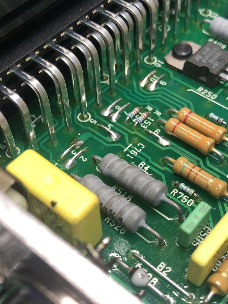
The schematic link above is dead. Does anyone have the schematics?
What else would be burned up in here?
thanks!
Just picked up up a car that sat for a bit. No start traced to no spark. Opened up the DME and it was rattling. The R528 fell out when I opened it up and the R518 had one pin that had in-soldered itself
i put them back but still no spark.
Now put back:
The schematic link above is dead. Does anyone have the schematics?
What else would be burned up in here?
thanks!