When you click on links to various merchants on this site and make a purchase, this can result in this site earning a commission. Affiliate programs and affiliations include, but are not limited to, the eBay Partner Network.
So I have this 85.1 944 that's an intermittent no spark/start. I've gone through the No-Start "flow chart" in the FSM and haven't found anything that would cause a no spark/start situation other than what could be maybe a cold solder joint in the DME? Alarm is bypassed per Clarks Garage instructions. New speed/reference sensors, new cap, rotor, recently replace waterpump and belts (started regularly'ish prior to changing). Had some issues setting the timing but I think I've gotten it straightened out since it will start intermittently although it runs pretty rich when it will start. Could it be a cold solder joint on the DME? It's been sort of cold in PA the last few weeks but there was a warm day last week where the car actually started but it ran like trash. Earlier this year when it was above 60F all the time it would start regularly after I fixed a leaky one way valve at the fuel pump.
Every time I test for 12v on terminals 18 and 35 (DME power) I get battery voltage (correct). Battery voltage today was about 12.2v after some cranking to check sensor waveforms.
I can jump 12v to the fuel pump and hear it run and know that it and the fuel injectors work when cranking because I smell fuel and my plugs will get fouled so I clean them (yes, I know, they're cheap to replace but if I replaced them after every few times of diagnosing/fouling it'd have gotten expensive a while ago). Fouled plugs also wouldn't explain a no spark unless Im missing something
I have a uScope (single channel pocket scope, amazing little tool) and my waveforms look good for the Speed/Ref sensors -- resistances are within spec
Reference
Speed
When I check the voltage between ground and term 1 and term 15 on the ignition coil (key on) I'll get battery voltage on term 1 and usually term 15(green wire) but sometimes I'll get appx 2v less on the green wire -- not sure if that is the coil causing the drop or something else in that circuit. Coil is new and wasn't the issue. All resistances are within spec.
Sometimes my inline spark tester will spark on any of the plugs I've put it on and sometimes it wont.
I've done the check for the FPR where you unplug one of the injectors and still no change.
I've checked the resistance in the wire from the coil to the distributor cap and get very little (maybe 6 ohms, not sure if that's an issue or not), plug wire resistance checks out for cylinders 1-4
I have my doubts about the DME temp sensor but that shouldn't stop it from sparking, should it?
It randomly started the other day and the only real difference between then and more recently was the outside temperature being about 63F which is leading me toward maybe a cold solder joint in the DME?
Possibly a bad ground? I know the DME will ground the green wire to spark the coil but I haven't found any documentation that states which pin on the DME is used to ground the coil.
I think you mean DME relay or are you talking about the actual DME which is the ECU?
Have you jiggled the harness at back of the engine for the speed and reference sensors as the harness back to the DME(ECU) is very old and prone to cause these issues?
If you are referring to the relay as the DME can you please stop, as it is not cool or anything and just leads to confusion and until now I have only seen N00bs on on FB groups doing it.
I'd replace the DME relay with the excellent solid state unit from Focus9 and eliminate that issue permanently. Probably a good idea to replace the harness back to the DME(ECU) with the one from Lindsey Racing to eliminate that too
Hey Joshua, I'm working on a 1984 n/a with the same problem. I have no tach bounce, but starts fine sometimes. DME relay jumpered, spark tester on #1 plug wire. When I see spark on the tester, it starts and runs fine, tach works good when running.
Check the connector just above the brake booster for corrosion.
"When I check the voltage between ground and term 1 and term 15 on the ignition coil (key on) I'll get battery voltage on term 1 and usually term 15(green wire) but sometimes I'll get appx 2v less on the green wire -- not sure if that is the coil causing the drop or something else in that circuit. Coil is new and wasn't the issue. All resistances are within spec."
With engine off, key on, you should have 12 VDC on both sides of the coil. The DME grounds one side to provide spark.
"Possibly a bad ground? I know the DME will ground the green wire to spark the coil but I haven't found any documentation that states which pin on the DME is used to ground the coil."
Disconnect the green wire and check the resistance between the coil side and the DME connection for continuity. Resistance should be very low.
I believe Pin 1 is the DME pin out for the coil connection, or you can search online. You should also look for an online factory service manual for your 944, it will have electrical diagrams in it. It may take a bit to understand the electrical diagrams, but if you're good with a scope, then you will pick it up quickly. You can view this link: https://rennlist.com/forums/924-931-...t-diagram.html
DMEs do sometimes develop intermittents. The heavier parts tend to crack the solder joints. You might try resoldering the PCB around the power transistors on the heat sinks in the DME. Can't hurt.
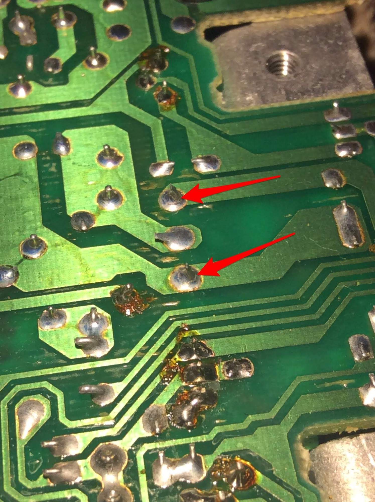
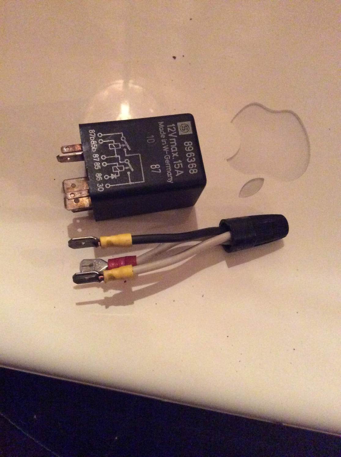
If you do decide to pull & open the DME/ECU, look for these little lines. You can barely notice them. I used my phone's zoom to find them. Re-soldering these (simply touching a hot soldering iron on them) fixed my intermittent stalling and no-start issue
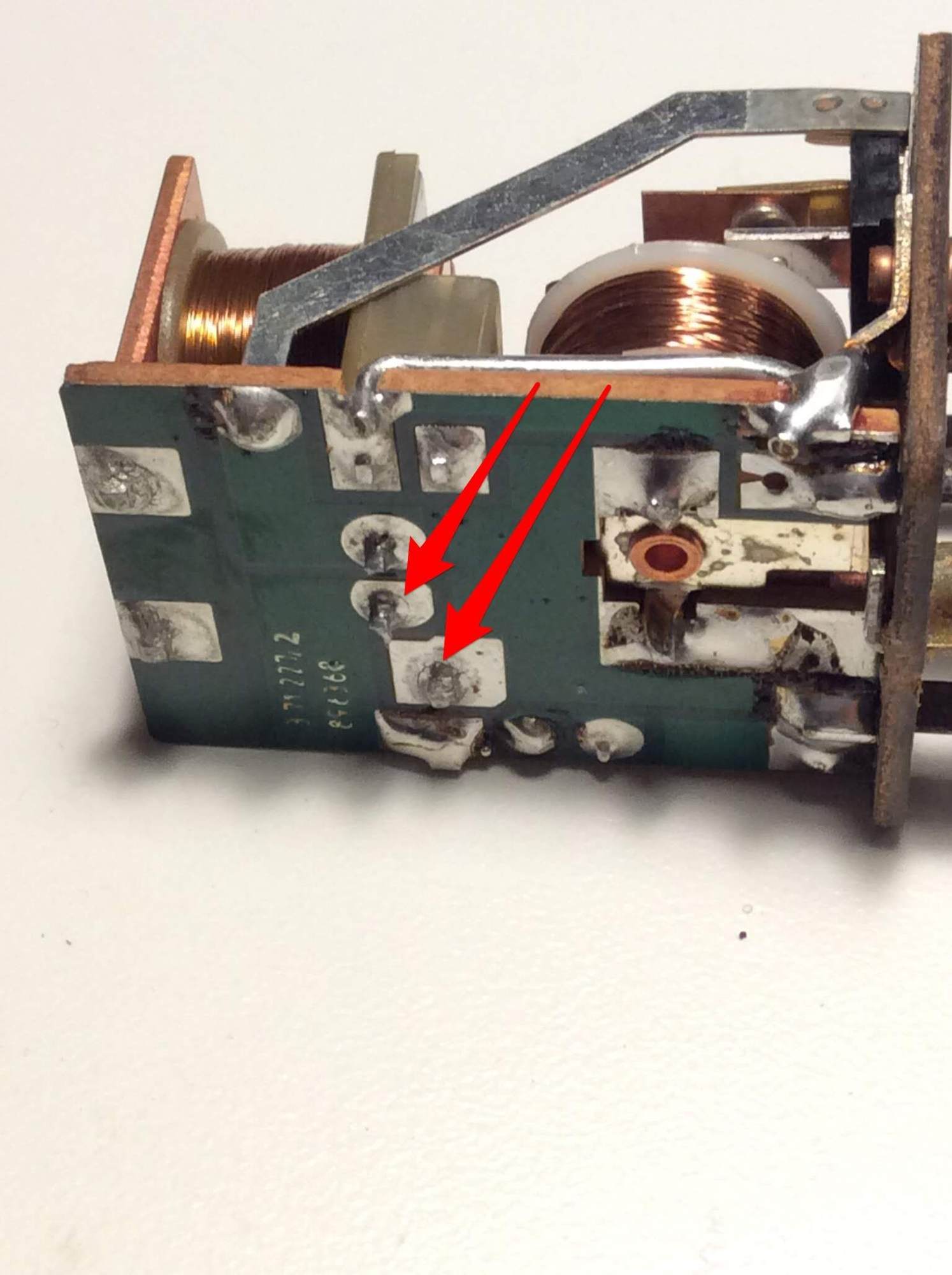
BTW, these little "cracks" show up everywhere. Here they are on the DME Relay
Might as well fix those. I did. To test the DME Relay, make the little connector and use that in its stead
I think you mean DME relay or are you talking about the actual DME which is the ECU?
Have you jiggled the harness at back of the engine for the speed and reference sensors as the harness back to the DME(ECU) is very old and prone to cause these issues?
If you are referring to the relay as the DME can you please stop, as it is not cool or anything and just leads to confusion and until now I have only seen N00bs on on FB groups doing it.
I'd replace the DME relay with the excellent solid state unit from Focus9 and eliminate that issue permanently. Probably a good idea to replace the harness back to the DME(ECU) with the one from Lindsey Racing to eliminate that too
I mean the actual DME.
Waveforms above were taken at the DME plug (back probed) so I have, at least at that point in time, good signal for both sensors.
I'd like to get the solid state relay one of these days -- the pump priming feature is something all 944s could have definitely used but before I get one of those I'd like to pin down why I have this intermittent no start.
One day I'll redo the harnesses too as a preventative measure. Thanks!
Hey Joshua, I'm working on a 1984 n/a with the same problem. I have no tach bounce, but starts fine sometimes. DME relay jumpered, spark tester on #1 plug wire. When I see spark on the tester, it starts and runs fine, tach works good when running.
Do you have the factory alarm? If so, that interrupts the (-) negative on the coil which also feeds the tach. Maybe a loose solder joint in there?
Check the connector just above the brake booster for corrosion.
"When I check the voltage between ground and term 1 and term 15 on the ignition coil (key on) I'll get battery voltage on term 1 and usually term 15(green wire) but sometimes I'll get appx 2v less on the green wire -- not sure if that is the coil causing the drop or something else in that circuit. Coil is new and wasn't the issue. All resistances are within spec."
With engine off, key on, you should have 12 VDC on both sides of the coil. The DME grounds one side to provide spark.
"Possibly a bad ground? I know the DME will ground the green wire to spark the coil but I haven't found any documentation that states which pin on the DME is used to ground the coil."
Disconnect the green wire and check the resistance between the coil side and the DME connection for continuity. Resistance should be very low.
I believe Pin 1 is the DME pin out for the coil connection, or you can search online. You should also look for an online factory service manual for your 944, it will have electrical diagrams in it. It may take a bit to understand the electrical diagrams, but if you're good with a scope, then you will pick it up quickly. You can view this link: https://rennlist.com/forums/924-931-...t-diagram.html
DMEs do sometimes develop intermittents. The heavier parts tend to crack the solder joints. You might try resoldering the PCB around the power transistors on the heat sinks in the DME. Can't hurt.
The 9 pin connector is ok. I check that/there regularly for troubleshooting all of the issues with this car :sigh:
Good idea, will check the resistance in the green wire and report back. The 2v difference was from the post to the post and shouldn't take into account any voltage drop further down the lines is that right?
When I say ground I'm meaning what route does the DME use to ground the input from pin 1 - i.e. does the DME connect pin 1 to pin 19 (internally) to complete the circuit?
Thanks for you help!
Last edited by Joshua Leeds; 12-07-2021 at 08:41 PM.
"The 2v difference was from the post to the post and shouldn't take into account any voltage drop further down the linez is that right?"
There shouldn't be any voltage drop across the coil. See more below.
"When I say ground I'm meaning what route does the DME use to ground the input from pin 1 - i.e. does the DME connect pin 1 to pin 19 (internally) to complete the circuit?"
The DME pin 1 goes to ground to "charge" the ignition coil (current flows from the car battery to the 12 VDC battery post of the coil, thru the coil, and out to the DME grounded green wire side of the coil).
When the DME pin 1 goes to 12 VDC, the magnetic flux in the coil collapses and through the coil's step up transformer action generates the ignition high-voltage spark the rotor and distributor cap send to the correct cylinder.
Simply stated:
When engine off, key on, the ignition coil has 12 VDC on both posts.
When the DME grounds pin 1, the green wire side has close to 0 VDC.
When the green wire goes back to 12 VDC the ignition coil makes spark.
If you have 2 VDC drop across the coil, then either the green wire is resistive, there's a bad connector, or the DME has an issue.
Ignition issue is either bad wiring (check resistance of green wire from coil post to DME pin1), or a bad solder joint in the DME (resolder PCB), or a failed active device (DME transistor).
My guess is first or second condition. Failed DME parts don't work and then stop working. However, intermittent solder connections do, and so do connectors and corroded or damaged wiring.
Hope that helps!
Paul that is an excellent description of primary ignition!! If Rennlist had a glossery of terms for less experienced folk, that should definitely be in there!
That being said, hypothetically, if I were to depin all of the grounds from the DME connector, there would be no where for pin 1 to send the voltage (to ground). Do you know which pin I would have to put back in the harness so the DME would be able to ground the voltage sent to Pin 1 from the coil?
Thanks for clearing up about the coil resistance. I wasn't sure if the coil created some resistance due to heat or anything like that.
UPDATE
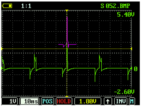
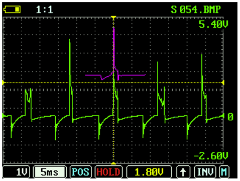
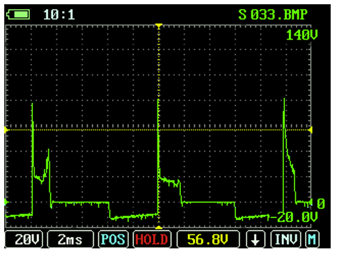
I took Dan Martinic's advice and so resoldered the joints on the DME relay today. I also pulled the fuse for the headlight motor because I saw in my first post to Rennlist that I had better electrical system performance by pulling the headlight motor relay. Fuse is easier to get to. If anyone has any ideas about that I'd love to hear them. Put the battery on a trickle charger for maybe an hour or so and 'lo and behold the car started! Took some time to try and get some waveforms to share for anyone that might be interested in them. I've never seen any waveforms in posts so I hope I don't get burned at the stake
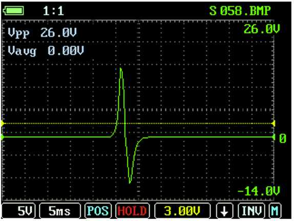
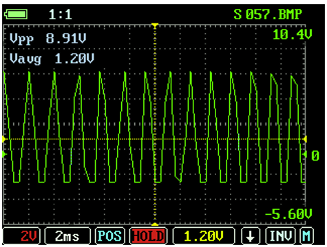
Secondary ignition waveforms (spark plugs) (1, maybe 2, injectors may be sticky/clogged. In the top image I believe it to be the center waveform because of the lack of spark line -- the little downward bridge that connects the two spikes in the waveforms on either side) On these cars with Ignition Coils and electronic ignition, Primary and Secondary ignition waveforms look very similar
Primary Ignition (Ignition coil) Again, these are very similar to secondary ignition waveforms. The big difference is the squiggle at the beginning (secondary) vs the square'ish drop at the beginning (primary) Primary ignition waveform
"That being said, hypothetically, if I were to depin all of the grounds from the DME connector, there would be no where for pin 1 to send the voltage (to ground)."
That statement is correct. The circuit would be incomplete.
"Do you know which pin I would have to put back in the harness so the DME would be able to ground the voltage sent to Pin 1 from the coil?"
All of the DME grounds are important and must be grounded. Some are analog, some are digital, so all of them matter at the same time.
Your scope graphs show ignition. Primary and Secondary waveforms should appear similar because they come from the same transformer, the ignition coil.
Based on your waveforms see if you can connect the high voltage lead (coil to distributor cap) directly to a spark plug. If you crank the engine, you should see fairly rapid spark across the plug gap. A used plug wire should allow you to do this. You need to verify strong and consistent spark.
Consistent spark verifies that the flywheel crank sensors are working, the DME and DME relay are working. and the coil and related wiring are good.
After that it is a fuel issue. Unless your engine timing belt is mistimed.
The DME relay handles power to the fuel pump, so your resoldering work may have fixed that.
Take the black cove off the DME relay and confirm the armature moves and the contacts are in reasonably good condition.
Last edited by PaulD_997C4S; 12-09-2021 at 11:16 PM.

 12-06-2021 | 07:12 PM