When you click on links to various merchants on this site and make a purchase, this can result in this site earning a commission. Affiliate programs and affiliations include, but are not limited to, the eBay Partner Network.
As part of my MicroSquirt project (see here) I’ve decided to use a front-mounted crank sensor for engine position sensing. At some point I would like to switch back to using the stock speed and reference sensors. However this will require some sort of conditioning circuit to work with MicroSquirt, which is a project I don’t want to take on right now.
From everything that I’ve read, the big issue with a front-mounted crank sensor is how to mount the sensor. Clewett Engineering has a pretty sexy adapter kit that includes everything you need. However, for me personally, the price is fairly steep for something I hope to do away with in the future. There are various other approaches to mounting the sensor, including a block that attaches to the A/C belt tensioner. But these schemes seem to have met with mixed success. Plus, I’ve deleted the A/C on my car but left the alternator in the stock position, which means I don’t have a belt tensioner in the necessary position. (I’ve also deleted the power steering, so in fact I don’t have either tensioner).
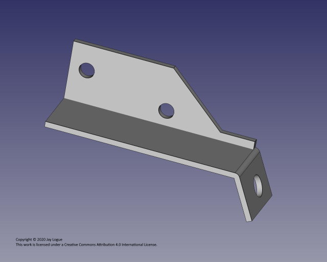
After noodling a bit I came up with the following design:
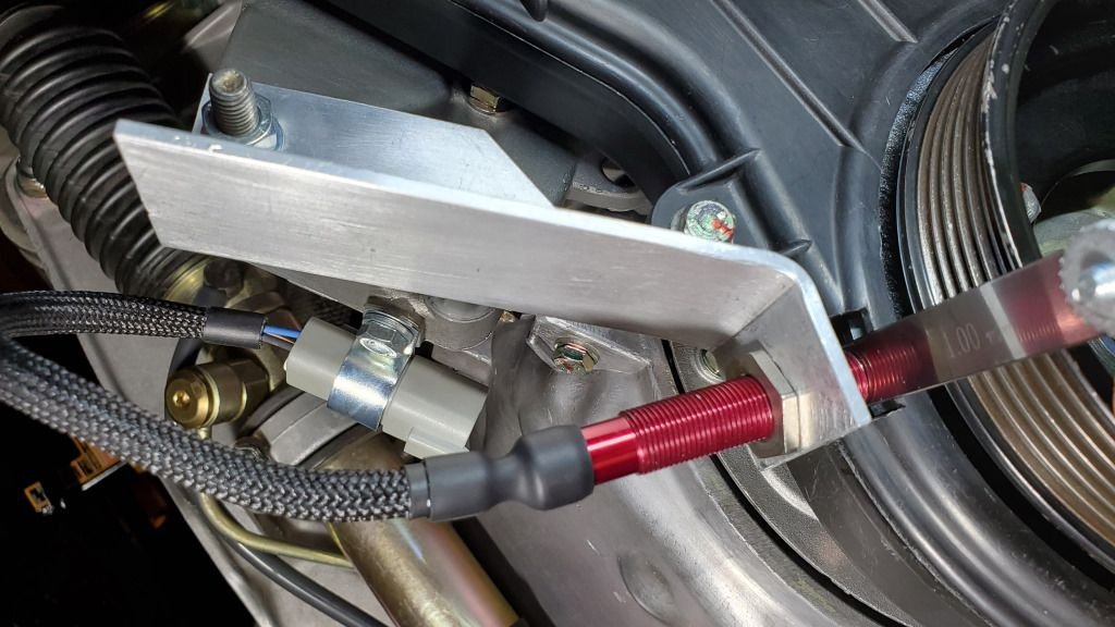
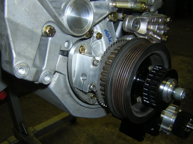
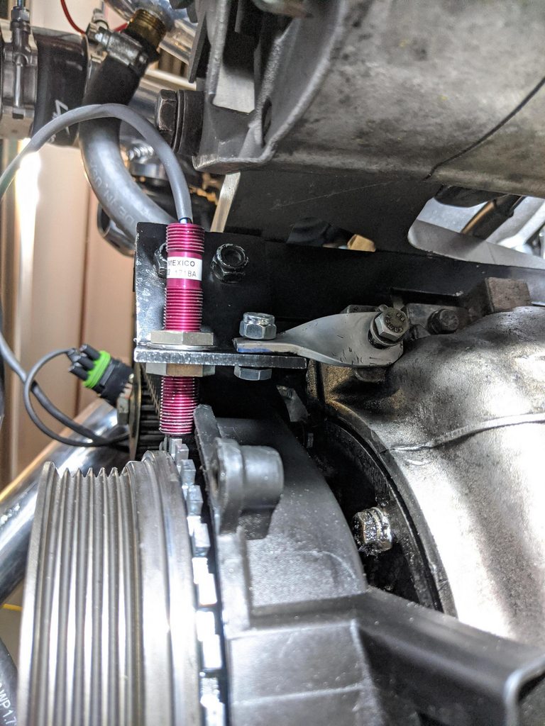
This bracket mounts where the A/C and P/S belt tensioners normally mount, on the lower balance shaft seal / gear carrier. The bracket is designed to hold a hall sensor with a threaded body, allowing the gap between the sensor and the trigger wheel to be adjusted with locking nuts. A spacer is used behind one of the mounting holes to create a level plane for clamping the bracket.
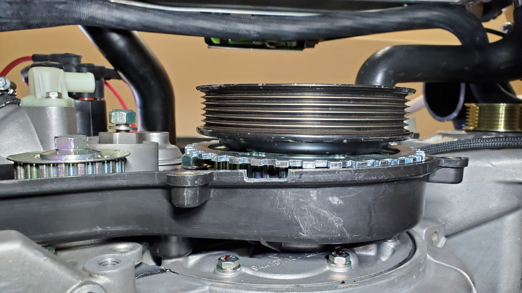
Similar to others, I’m using the 6” 36-1 trigger wheel from goingsuperfast.com.
One of my goals was to be able to make the bracket using only simple tools, e.g. drills, saws, files, etc. So the design is based on a small section of standard 1.5” aluminum angle, which I cut and filed to the desired profile. The mounting holes were drilled with a press, but could just as easily be made with a hand drill.
The one unusual feature of the bracket is the 115 degree bend for the sensor tab. This I did by annealing the aluminum using a hand-held torch and the candle soot method. After this I was able to bend the tab in a vise using a simple lever and an angle gauge.
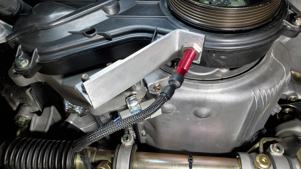
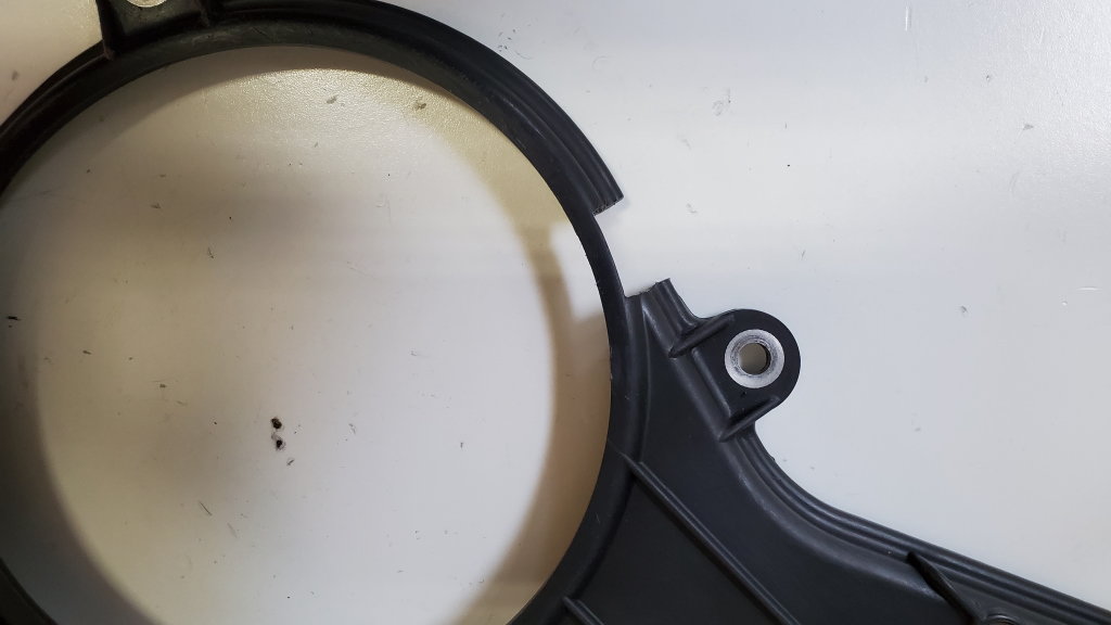
I used a dremel to carefully notch the belt covers to allow the sensor to pass through. I further cut away enough of the plastic on the front cover to allow me to insert a feeler gauge to set the correct gap. This left a rather small “isthmus” of plastic between the two sides of the cover. However, given the way the front and back covers mate, I don’t expect there to be much stress on this part.
I have a few other things to do before I can start the car using the new sensor. My hope is the bracket will be stable enough to ensure a reliable signal. Time will tell.
clever!
i think the bracket will be sufficient, if anything add a triangulation gusset on at least on side of the "bend" to keep the angle where it needs to be.
Dare: looks very nice, simple and clean yet seems robust, seems like it ought to be rigid enough to be reliable. Worst case, as noted, a gusset on the angle to triangulate and lock it down from any flexing, but it seems pretty sturdy.
clever!
i think the bracket will be sufficient, if anything add a triangulation gusset on at least on side of the "bend" to keep the angle where it needs to be.
Good idea. I bet the gusset could be even be attached with adhesive, for those who don't have ready access to a welder.
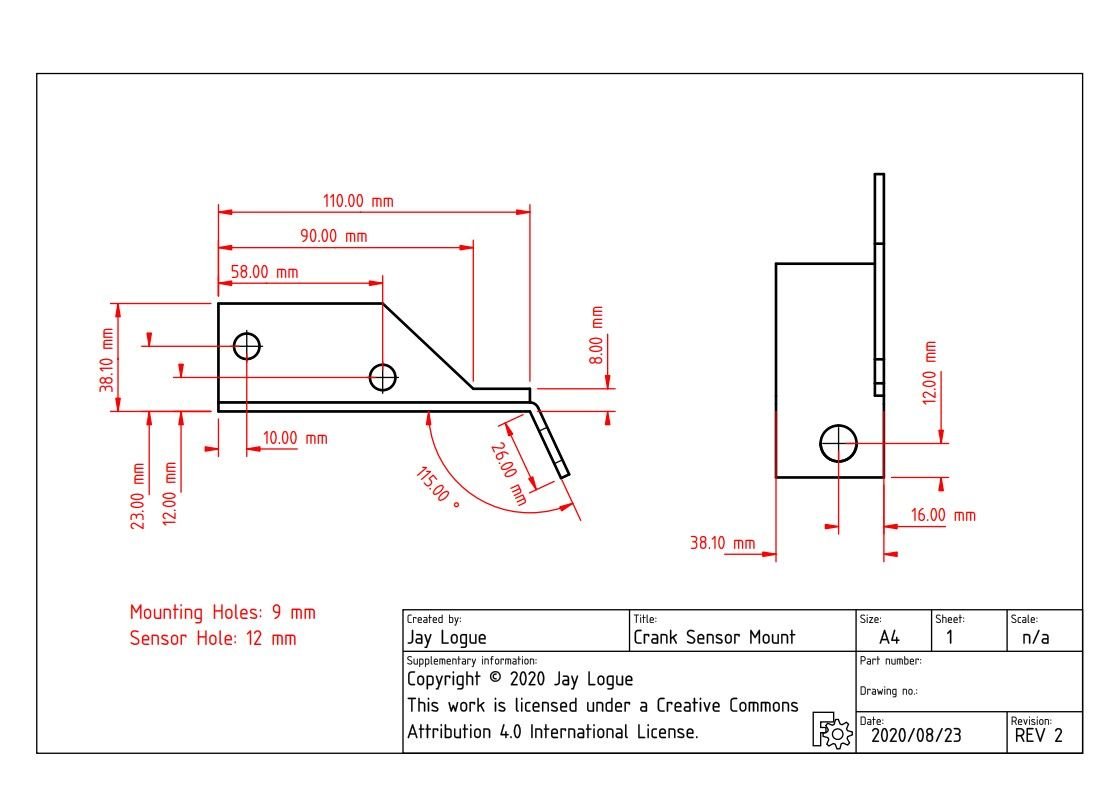
In case anyone wants to build their own, here are the dimensions of the bracket:
The spacer used behind the left-side mounting hole is from www.metalspacersonline.com. Dimensions are OD: 5/8", ID: 5/16", length: 11/16". (I have a bunch of these left over, so PM me if you want one).
Looking back at the design, there are a couple of things I might do differently:
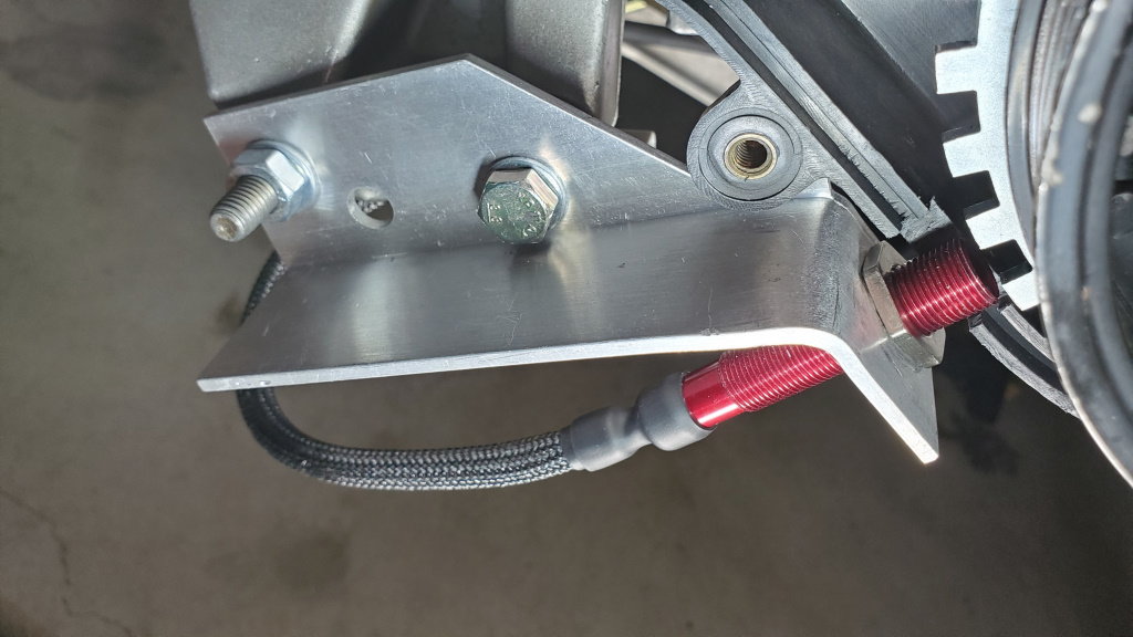
- The left side mounting hole is too close to the inside corner of the bracket, making it impossible to get a socket over the bolt head. To correct this, I would make the sensor tab angle more acute and rotate the plane of the bracket base away from the pickup points until there is enough clearance.
- The sensor tab is just a little too close to the belt covers to fit a standard size open end wrench around the lock nut. I would shift the pickup points ever so slightly to move the plane of the sensor tab 1-2mm away from the centerline of the crank.
Nothing that a little trigonometry couldn't solve.
That is a much more elegant piece than the one I cobbled together. I actually came around from the other side and slipped the mount under the A/C delete bracket while shimming up the two upper bolts so the bracket still sits flush. My first attempt only worked for a while because there was too much flex in the mount and it eventually contacted the trigger wheel and zinged off the tip of the hall sensor. I decided to add a triangulation to the oil pan bolt and that has given me flawless operation for the last couple months. In fact I get zero trigger losses now when I'd pick up 1 or 2 at cold idle before.
That is a much more elegant piece than the one I cobbled together. I actually came around from the other side and slipped the mount under the A/C delete bracket while shimming up the two upper bolts so the bracket still sits flush. My first attempt only worked for a while because there was too much flex in the mount and it eventually contacted the trigger wheel and zinged off the tip of the hall sensor. I decided to add a triangulation to the oil pan bolt and that has given me flawless operation for the last couple months. In fact I get zero trigger losses now when I'd pick up 1 or 2 at cold idle before.
Thanks for sharing the picture. Your mount looks similar to one created by a guy who transplanted a 944 engine into a 85 golf (described here). Can't quite tell if it would work with the alternator in the stock location.
Glad to hear its working so well for you. Would you mind sharing the sensor gap you're running? It looks pretty big from the picture (which is encouraging).
It's about 1mm at least. I even had it gapped bigger than that and it still worked awesome. The spec is 1.5mm air gap, so there is some room to work with. I think a stable gap is far more important than getting the absolute tightest gap. One thing I had to fiddle with is the mounting of the trigger wheel to get it centred on the crank. Give the crank a couple of turns and measure the gap on different teeth just to make sure.
Good idea. I bet the gusset could be even be attached with adhesive, for those who don't have ready access to a welder.
Great work! I can TIG a little gusset on for you if helpful. Won't be Instagram pretty, but functional for sure. I also think I have an assembled LM1815-based conditioner for the megasquirt somewhere, which I put together when developing that sensor tester I made... It's yours if you want it, but have to say the MAX9926 is probably the way to go (or steal an S100 chip off a bad DME).
Great work! I can TIG a little gusset on for you if helpful. Won't be Instagram pretty, but functional for sure. I also think I have an assembled LM1815-based conditioner for the megasquirt somewhere, which I put together when developing that sensor tester I made... It's yours if you want it, but have to say the MAX9926 is probably the way to go (or steal an S100 chip off a bad DME).
Thanks for the kind offer, Tom. I'm going to see how it works without the gusset first.
I do like the look of the MAX9926. As I understand it, the trick with MS and the stock 951 sensors is the number of teeth on the speed sensor, which outstrips the processing speed of the system. I think would be possible to create a uC-based signal processor that simulates the output of a 36-1 wheel (or one of the other supported patterns) from the stock sensor inputs. However, considering the complexity of building such a thing, I've been wondering if I should just dive in and incorporate one of the Speeduino Teensy 3.5 designs into my MS/951 board. That would give me the ultimate flexibility. However, as I said before, that's a project for another day!
132 teeth outstrip the processing speed!? It's remarkable how much the Bosch engineers got out of the 8-bit 8051 processor. If I understand correctly, the MS system uses a 16-bit 50MHz processor that I would think is able to process circles around the 8051...? If the firmware is open-sourced, I wonder if you are better off eliminating inefficiencies in the MS code, stripping out unneeded loops and bloated functions from higher level programming, etc. and just feeding it the original 132 teeth through an S100 chip...?
Getting 36 accurate cross-over points from 132 teeth is above my pay grade, but unlike you, I'm a hack If you could do that, it would be a pretty useful adapter board for a lot of people I suspect...
 08-25-2020, 10:40 PM


 I also think I have an assembled LM1815-based conditioner for the megasquirt somewhere, which I put together when developing that sensor tester I made... It's yours if you want it, but have to say the MAX9926 is probably the way to go (or steal an S100 chip off a bad DME).