When you click on links to various merchants on this site and make a purchase, this can result in this site earning a commission. Affiliate programs and affiliations include, but are not limited to, the eBay Partner Network.
Inspired by odonnell’s latest project, and the generous contributions from Dougs951S, I have decided to take the plunge and build a MicroSquirt-based standalone system for my 951 track car. A standalone system has always been part of my plan for this car, and with a number of other mechanical things out of the way, now seems like a good time to start.
I should say that before settling on MicroSquirt I did seriously consider going with VEMS. While I have no direct experience with it, it really does seem like a great system. I’m also greatly appreciative of the attention given to the 944 community by the proponents of VEMS (most notably, raceboy), which I feel we’re all lucky to have. I think anyone looking for a replacement engine management system would do well to investigate VEMS.
That said, for me, more than half the enjoyment of building a project car comes from the building itself. (It would have to be, considering how little time my car has spent on the road!) So starting with a relatively open and DIY system like MegaSquirt makes sense. And the strong community surrounding it gives me a great opportunity to learn.
It's always good to start any project with a clear set of goals, so here are mine:
GOALS
Based on the fully-built MicroSquirt module (like odonnell’s project)
Support for a modest set of engine management features, including:
Batch or semi-sequential injector firing using the stock wiring configuration
Stock coil/distributor or wasted spark
Up to 2 engine position / speed sensor inputs
Speed/density air metering, with MAP sensor integrated into the ECU
Knock detection (via KnockSenseMS)
Boost control
Wide-band O2 sensor support
Stock ICV support
Easily integrated into the existing wiring harness with simple, reversible modifications.
Expansion options for additional sensor inputs (oil temp, EGT, etc.).
Clean physical installation in the standard DME location, with no “rat’s nest” of wires inside or outside the ECU.
Easy access for tuning, with a physically and electrically robust connection.
External CAN bus access, for adding things like gauges, dashboards and more sensors.
Unified proto-board design, with option to produce a custom PCB at a later point.
DIY and budget friendly, emphasising low-cost or repurposed components.
Nothing here will be radically innovative as compared to other builds. But my hope is to end up with a system that is clean and reliable, and in the process, push myself to better understand the workings of engine management systems. I’ve never done this before, so bear with me as I learn.
I also hope that the project will be helpful to others. To that end, everything I produce, including any code, board layouts or documentation, will be openly available (including for commercial use, should anyone be so inclined).
Finally, I should note that, prior to starting this project, I undertook a complete rebuild of my engine wiring harness. The new harness remains compatible with the stock DME/KLR, but I incorporated a number of changes in anticipation of my move to a standalone system, such as adding extra wires for new sensors. What this means is that, for some parts of this project, the details of the wiring will be unique to my car. That said, nothing within the ECU unit itself will be specific to my wiring harness. And as I go along I will try to point how one could achieve the same results without doing an extensive harness rebuild.
In many ways the physical construction of an ECU centers around the harness connection. This is especially true in this case given that I have opted retain the 35-pin connector used in the OEM harness. New versions of the DME side of that connector are not readily available, which relegates one to scavenging them from old units. Once you decide to take the connector, reusing the housing along with it is a logical next step.
Both odonnell and Dougs951S have chosen to reuse the connector and housing from an early DME. Similar units were used on many models of car, so cost and availability is pretty good. The physical arrangement of the unit is quite amenable to the DIYer, making it relatively easy to repurpose. One downside to the early DME case is that it traps the harness connector within the housing when the connector is soldered to a PCB. This isn’t a problem for people doing discrete wiring from the connector. But I want to solder the connector to a PCB and still have the option of removing the PCB from the housing.
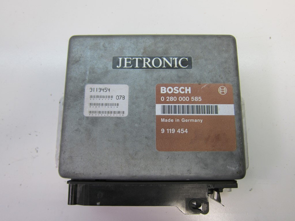
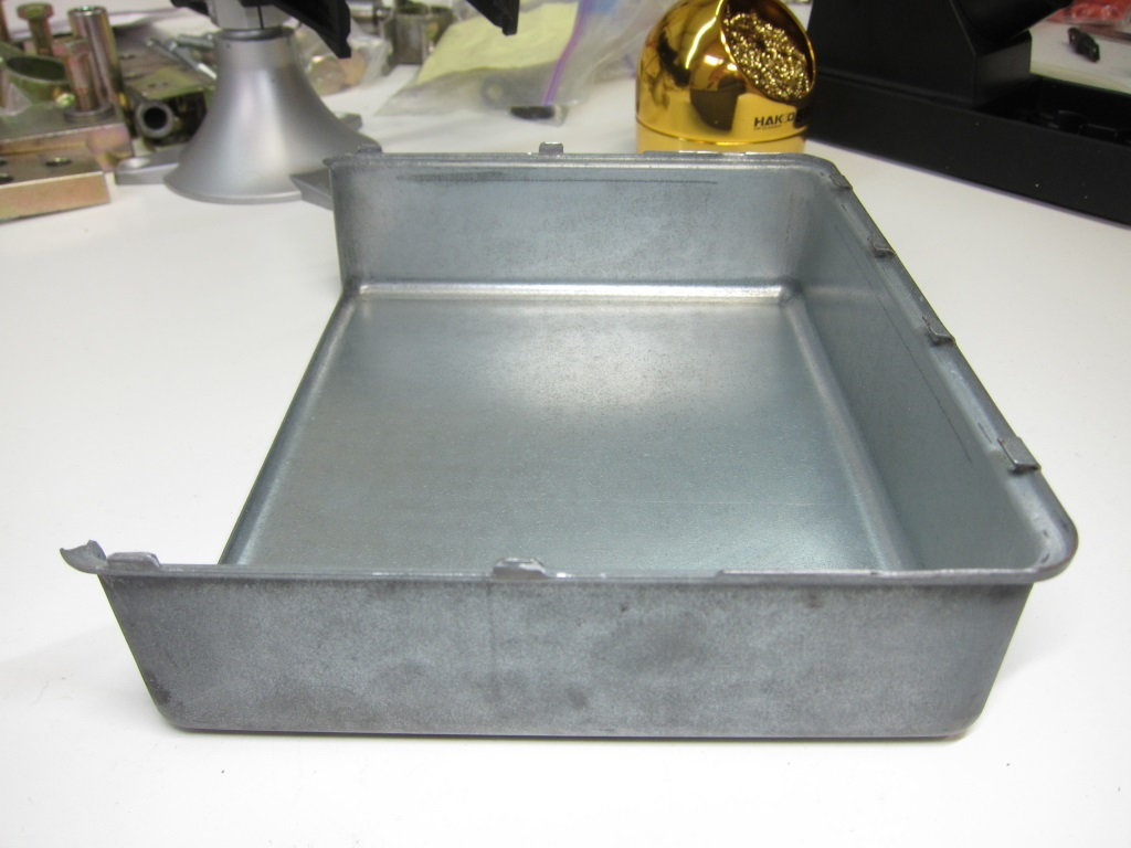
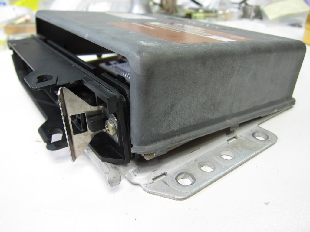
The later DMEs have a simpler physical construction than the earlier ones. The PCBs and connector are screw mounted to a flat bottom plate, which is then wrapped by a sheet metal shell. Again, similar units were used on many others cars. One of these was the 90’s SAAB 900 Turbo, for which I was able to acquire a unit in unknown working condition for $25. This was great because it meant I didn’t have to cannibalize a working 944 DME for my prototype.
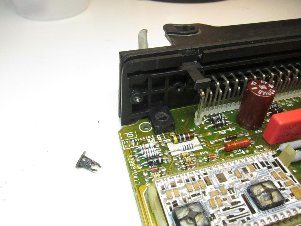
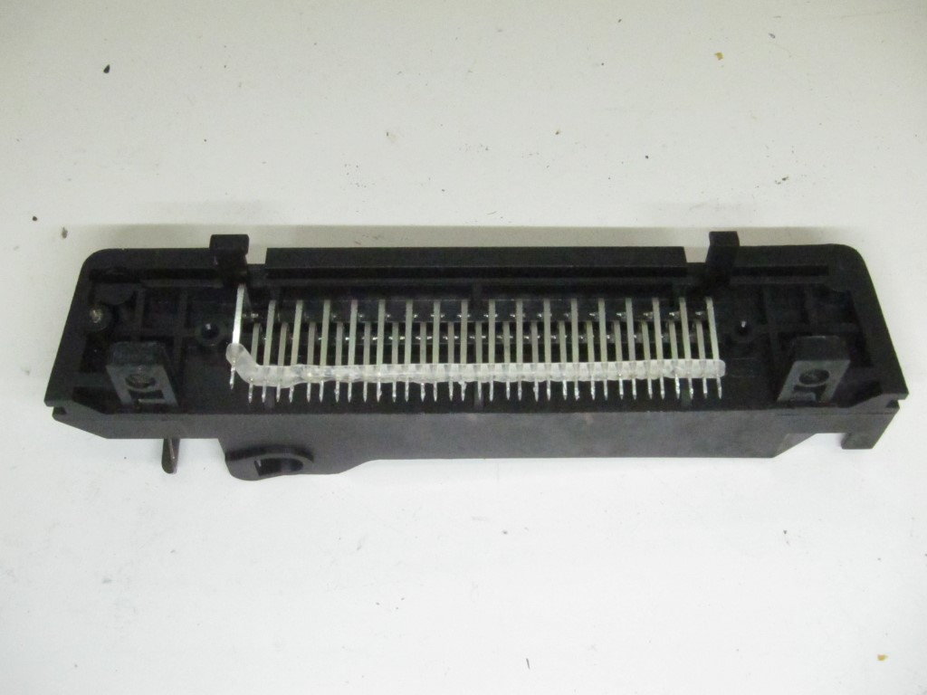
The SAAB 900 DME is a single-board design, with the connector physically secured to the PCB using a rivet with a threaded bore (kind of like a nutsert). This I drilled out using a slightly oversized drill bit. I then desoldered the connector from the PCB using a $40 hot air station, which was relatively easy given I wasn’t interested in preserving the board.
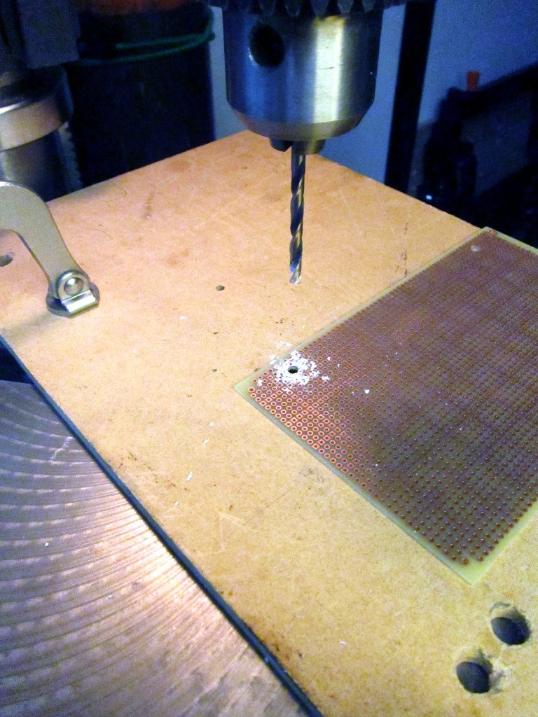
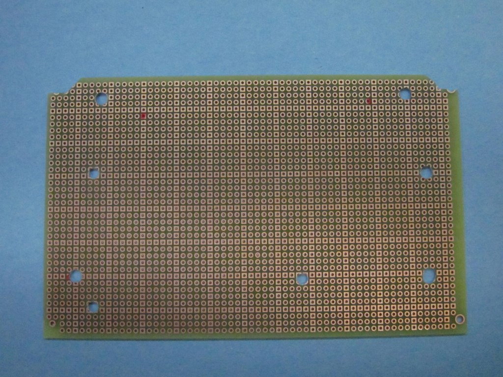
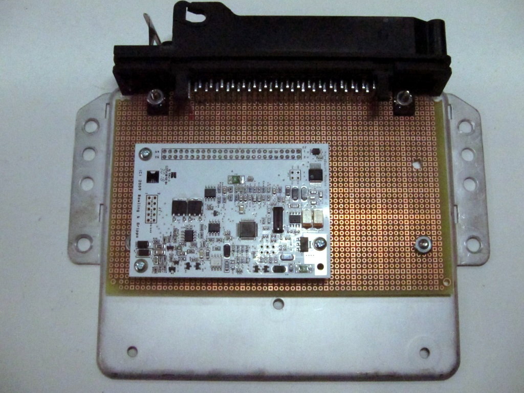
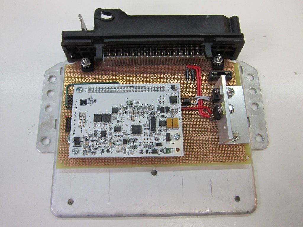
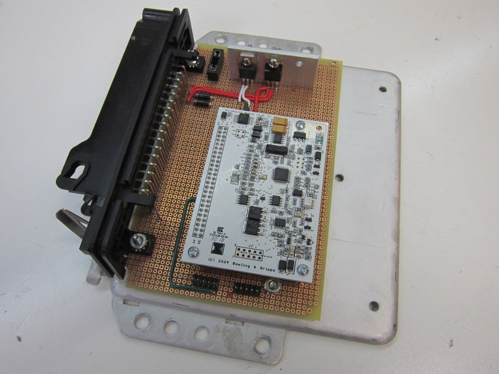
The original Bosch PCB measures 160mm x 135mm. Very conveniently I was able to find a pad-per-hole prototyping board that measured exactly 160mm wide, and which was long enough to reach some existing mounting holes in the base plate. This will be used as a main board, to which the connector and other components will be soldered. The MicroSquirt module is mounted as a daughter card, with point-to-point wiring connecting everything together.
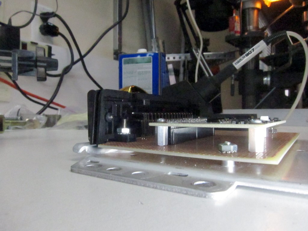
After some drilling, and a little trimming of the proto-board to clear the connector, I was able to test assemble the ECU.
The value of this design is that I should be able to replace the proto-board with a custom PCB at a later date for a more turnkey approach. If I do that I’ll make the design available for others to copy.
One downside to the later DMEs is their use of fold-over tabs to secure the cover. These were clearly designed for infrequent access. Since I expect to open the unit often, my plan is use screws to hold the cover in place. This will work roughly as follows: I will attach extra long standoffs to the existing screws that hold the harness connector to the base plate. These will reach up to just under the level of the cover when it is in place. Corresponding holes in the cover will allow it to be screwed to the standoffs, securing the cover at the connector end. At the opposite end, I will leave the tabs on the cover in their folded over position, but remove or trim the tabs along the sides of the cover. To install the cover, you will hook the tabs onto the base plate opposite the connector, swing the cover into position over the connector, and secure with two screws. Anyone with a dremel and a drill should be able to reproduce this.
Next order of business is figuring out how each of the pins on the ECU connector will be wired. Ideally, most will retain their original purpose, requiring no changes to the existing harness. Others will need to be rewired to handle the new sensors / outputs used by MicroSquirt. Additionally, since all engine management duties will now be handled by a single ECU, some rerouting of existing signal wires will be required to accommodate signals that were previously going to the KLR.
In approaching the problem, it helped me to make a list of the things that need to be different, and those that should remain the same:
Add output for second ignition circuit, to support wasted spark
Add sensor ground and power connections needed for new sensors
Maintain existing switched power and ground connections
Maintain existing ignition output (for use with stock coil/distributor)
Maintain existing injectors outputs
Maintain reference sensor input
Maintain O2 sensor input (but switchable between NB and WB sensor types)
Maintain A/C compressor on input
Maintain engine coolant sensor input
Maintain fuel pump enable output
Maintain tach output to dashboard harness
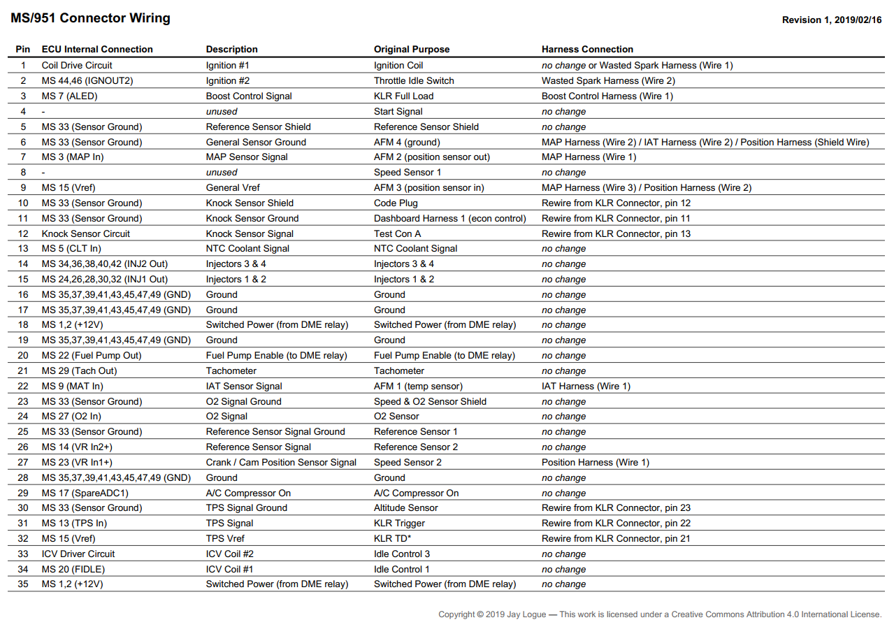
Based on this I have come up with the following configuration for the ECU connector:
The master copy of this configuration is published on Google Drive: MS/951 Wiring. It includes some additional notes not shown in the picture above.
In coming up with this configuration I tried to meet the following goals:
- Maintain as much of the existing harness wiring as possible, along with their existing connector positions.
- Require no splicing of wires in the stock harness. This means that all new connections are made using new add-on wiring harnesses, or by repurposing existing wires without changing their termination.
- Where wires must be re-routed from the KLR to the ECU, map the wires one-for-one into the ECU connector. Because the harness connectors for DME and KLR use the same type of terminal, this means you can simply extract the terminals from KLR connector and insert them into the ECU connector.
- As much as possible, arrange the connector positions for low-power sensor connections to be physically separate from high-power or pulsed connections.
- Maintain a few connector positions that are unused or easily repurposed to accommodate future expansion.
Note that, in some cases, external components like coil drivers will require access to switched power and ground. These connections are not routed through the ECU connector, and thus are not shown in the diagram above. In my rebuilt harness I made the power and ground junctions easily expandable. However for those working with the stock harness, this is the one area where splicing into existing wires may be required. I’ll try to explore the options for this in a later post.
Awesome work! I need to finish mine when I'm back from working offshore. Keep us updated. I'm interested in those PCBs if you ever have them made, I mentioned it before but some friends and I are looking at producing some new market items for the 944 in the next few years.
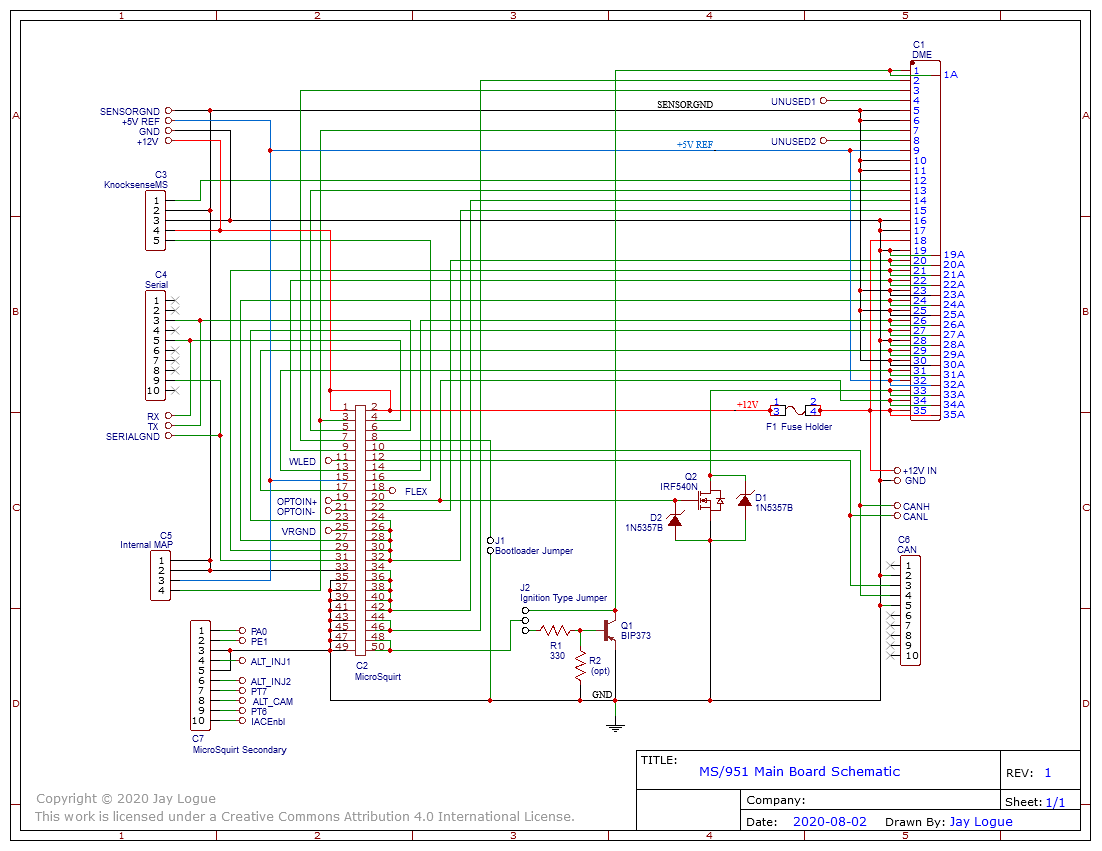
Since my hope is to eventually produce a PCB for my ECU, I spent some time drawing up a proper schematic for the main board. The schematic is largely derived from the wiring list described in my previous post. So most of the connections are simply routing pins on the DME connector to pins on the MicroSquirt module. However, there are a number of other circuits that are needed to make things work, including an ignition coil driver, an ICV driver, and connections to various other off-board components. These are described below.
The following is the preliminary version of the main board schematic. I will update this as I complete the prototype and verify the design.
Coil Driver Circuit
The coil driver circuit is the most straightforward of the two drivers. Although I intend to run a wasted spark configuration eventually, my plan is to run the car using the stock coil and distributor initially. When I do make the switch, I will also switch to using logic-level coils. Therefore the design only includes a single driver to accommodate the stock coil configuration. A jumper on the board makes it possible to bypass the driver when it comes time to switch to wasted spark.
The heart of the coil driver is the well-known Bosch BIP373 power transistor (Q1). This transistor is commonly used as a coil driver in MS applications, and provides a number of useful features beyond those offered in a standard power transistor, including over temp. protection. A small base resistor (R1) is used to limit the current draw from the MicroSquirt. An optional pull-down resistor (R2) is included in the design to allow a MOSFET to be used if that ever becomes interesting. However R2 should _not_ be installed when using the BIP373.
ICV Driver Circuit
The second driver is for the idle control valve. The 944 uses a dual-coil (3-wire) ICV which is driven by the DME using pulse width modulation. The two coils in the ICV act in opposition to one another, with one coil causing the ICV to open and the other causing it to close. While MicroSquirt has the ability to control an ICV, it is only capable of driving a single coil.
To work around this, a number of people have devised ways to drive dual-coil ICVs from MS. The most common of these is to hard-wire one of the coils on all the time, and drive the other with the output from the MicroSquirt. A high-power resistor is placed in series with the always-on coil to allow the driven coil to overcome its force.
While this is reported to work, it isn’t how Bosch intended these ICVs to be controlled. If you look closely at the schematics for the 944 DME, you’ll see that there are in fact two driver circuits for the ICV. These are driven from a single logic-level PWM output from the microcontroller. The drivers are arranged in a cascade fashion, such that when one coil is energized, the other is not. As the width of the pulses are modified, the balance of forces between the two coils changes causing the valve to move to a new position.
The FIDLE output of MicroSquirt is capable of directly driving one of the ICV coils. To drive the opposite coil I’ve incorporated a power MOSFET (Q2) that is switched by the output of the built-in driver. Thus the arrangement mimics the cascaded drivers in the 944 DME. Because the ICV is wired in a low-side switch configuration (i.e. where the driver energizes the coil by providing a path to ground), cascading the circuits naturally causes the outputs to be the inverse of each other, which is exactly what we want.
A common issue with driving inductive loads like the ICV coils is dealing with flyback from the coil when it gets switched off. This can cause huge voltage spikes that can damage the driving transistor. To avoid this I’ve included a 20V zener diode (D1) across the MOSFET output to limit the flyback voltage from the second coil. For first coil, the MicroSquirt documentation suggests that the FIDLE output can be directly connected to a coil without any flyback protection. However, since I’m also connecting the FIDLE output to the gate (input) of the MOSFET I’ve included a second zener (D2) to ensure that the maximum gate voltage of the MOSFET (Vgs) is not exceeded.
Note that I have yet to fully test the ICV driver circuit, but preliminary results suggest it should work fine.
Internal Connections
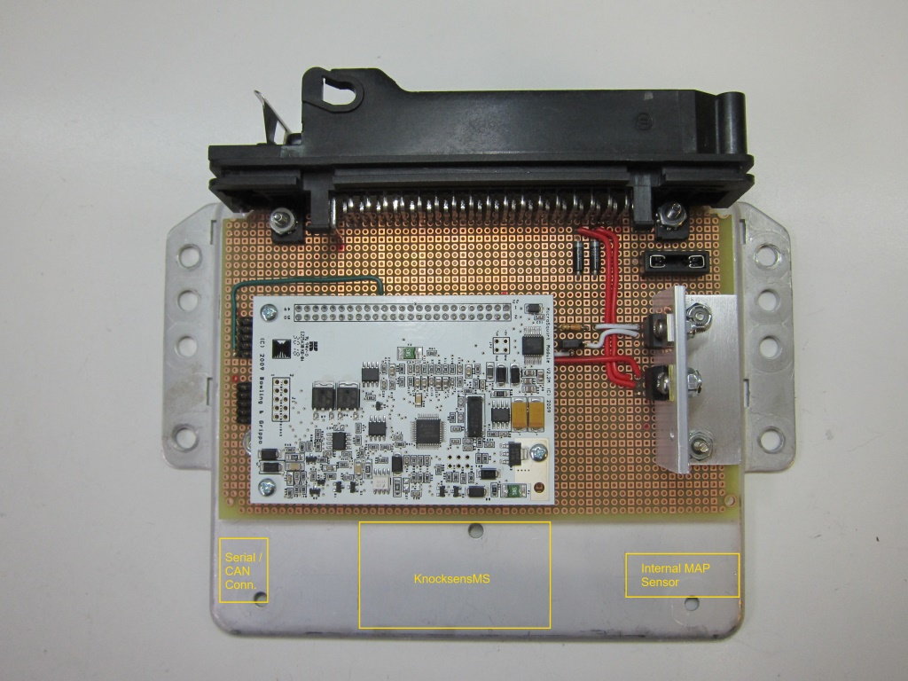
Not counting the MicroSquirt module itself, there are four additional components that will be incorporated into the ECU when I’m done: a KnocksenseMS module, an internal MAP sensor, a case serial connector and a case CAN bus connector.
The KnocksenseMS module comes in its own housing with a built-in push-style terminal block. Conveniently, the KnocksenseMS module fits perfectly in the space remaining in the case beyond the main PCB. The module needs power and ground connections, a shielded signal from the knock sensor itself, and a logic-level knock-detected output signal. These are routed to a 5-pin header on the main PCB, for which I will make a custom cable to connect to the terminal block.
The internal MAP sensor needs a shielded signal wire and +5V reference power. These are routed to a 4-pin header. This will also use a custom cable.
The case serial connector needs only three wires: RX, TX and serial ground. Here I chose to use a 2x5-pin header configured so that a standard DB-9 to IDC cable can be used, such as those used in PCs. These are readily available online.
The case CAN bus connector will also be a DB-9. Although CAN bus is generally carried over twisted pair wires, the spec allows for the use of IDC connectors and ribbon cable within a protected housing. So I chose a similar 2x5-pin header configuration as is used for the serial connection, allowing use of the same type of cable.
Revision History
2019-03-06 -- Updated to schematic rev 0.7. This revision reverses RX and TX on serial connector so that a computer can be connected without a null modem cable.
2020-08-08 -- Updated to schematic rev 1. This revision adds: an optional input pull-down resistor for Q1; an additional set of pads for the harness connector (C1) that makes it possible to use connectors with offset pins; and a set of pads that can be used to power the board when it is out of the car (+12V IN / GND).
Last edited by Dare; 08-08-2020 at 11:43 PM.
Reason: (see revision history)
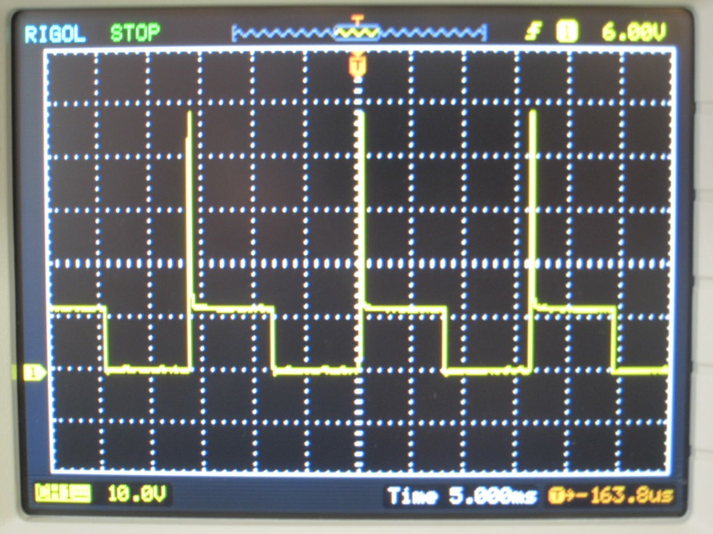
I had a chance to test the idle control valve driver circuit today using the MicroSquirt module. I was able to confirm that the FIDLE output on the MS is capable of directly driving one of the coils, but that it contains no flyback suppression circuit. [ Correction: This is wrong; see my later post. ] This is pretty much what I gathered from the MS schematic. This means that there’s a pretty substantial flyback voltage produced when the coil shuts off--upwards of 50 volts:
A zero voltage on the trace indicates when the coil is energized; +12V or greater indicates the coil has been shut off.
I then setup up my ICV driver circuit and tested driving both coils from the MS. As I didn’t want to pull the ICV from my car, I’m testing with an ICV from a late ‘90s BMW which I picked up for $20 on ebay. Except for the housing, I’m pretty sure it’s effectively the same as the 944 ICV.
As you can see in the following trace, the coils are properly driven in opposition to each other, and the voltage spikes are nicely clipped to around 20 volts by the zener diodes.
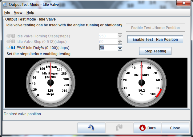
Varying the duty cycle in TunerStudio produced a nice smooth open and closing action on the ICV.
So I think the ICV driver circuit is good to go.
Last edited by Dare; 03-18-2019 at 11:49 AM.
Reason: Corrected misinformation
Thanks, Michael! Although to be fair, I have exactly *zero* experience tuning engines. So I'll probably need to lean on your help, and the help of others, to dial things in.
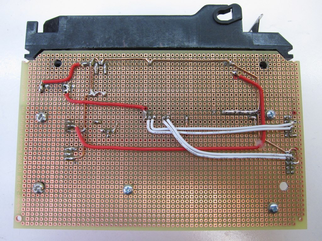
Made a little bit of progress over the weekend wiring up the new ECU. All the major power and ground circuits are wired, as are the drivers for the ignition and ICV. I mounted a blade-style mini fuse holder and made a quick-and-dirty heatsink for the transistors out of some 1” aluminum angle.
The point-to-point wiring is tedious. However the process has given me some insight as to how to layout the PCB when I eventually get to it. For example, I will likely move the ignition transistor to the other side of the board and give it its own heatsink, rather than keeping it next to the ICV transistor. The current placement of the ignition transistor is rather unfortunate in that it puts it at the exact opposite side of the ignition coil pin on the harness connector (#1). This results in a wire snaking around the board carrying high-current at (relatively) high-frequency, a potential source of noise for other more sensitive circuits. Relocating the driver next to pin #1 should help to reduce this.
I also settled on the placement of the serial and CAN bus headers and wired them up. My plan is to mount the external DB-9 connectors in the side of the case cover, with ribbon cable running to the headers. The spacing for this is tight, especially since I need to ensure adequate room outside the case for the external cable connectors when the ECU is mounted in its normal location. I finally settled on a placement that has the external connectors in a stacked arrangement on the right side of the case at the back (looking into the harness connector). This places the connectors beyond the end of the main board, avoiding any clearance issues with the stacked MicroSquirt board. (I was able to confirm that the ribbon cables coming out of the IDC connectors with strain-reliefs will just clear the top of the MicroSquirt board).
Still lots more to do.
Last edited by Dare; 03-11-2019 at 01:52 AM.
Reason: Typos
I had a chance to test the idle control valve driver circuit today using the MicroSquirt module. I was able to confirm that the FIDLE output on the MS is capable of directly driving one of the coils, but that it contains no flyback suppression circuit. This is pretty much what I gathered from the MS schematic. This means that there’s a pretty substantial flyback voltage produced when the coil shuts off--upwards of 50 volts:
A zero voltage on the trace indicates when the coil is energized; +12V or greater indicates the coil has been shut off.
I then setup up my ICV driver circuit and tested driving both coils from the MS. As I didn’t want to pull the ICV from my car, I’m testing with an ICV from a late ‘90s BMW which I picked up for $20 on ebay. Except for the housing, I’m pretty sure it’s effectively the same as the 944 ICV.
As you can see in the following trace, the coils are properly driven in opposition to each other, and the voltage spikes are nicely clipped to around 20 volts by the zener diodes.
Varying the duty cycle in TunerStudio produced a nice smooth open and closing action on the ICV.
So I think the ICV driver circuit is good to go.
Cool how did you set it up could never figure out the 3 wire so I am using a 2 wire out of a volvo but when I have to put stock DME back I have No ISV would like have true plug n play
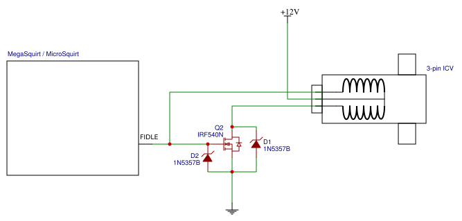
Here's a schematic showing the entire ICV circuit:
Note that one of the coils in the ICV causes it to open, while the other one causes it to close. The driver circuit inverts the FIDLE signal so that when one coil is on, the other is off.
MS doesn't seem to care which one is directly connected to the FIDLE pin. But this does make a difference as to whether 100% PWM duty cycle is all the way open or all the way closed.
Because MS doesn't care I haven't bothered to figure out which pin on the ICV connector is the open coil and which is the close coil. But it should be easy to determine.
 02-15-2019, 01:30 AM


 Thanks for sharing