When you click on links to various merchants on this site and make a purchase, this can result in this site earning a commission. Affiliate programs and affiliations include, but are not limited to, the eBay Partner Network.
Inspired by odonnell’s latest project, and the generous contributions from Dougs951S, I have decided to take the plunge and build a MicroSquirt-based standalone system for my 951 track car. A standalone system has always been part of my plan for this car, and with a number of other mechanical things out of the way, now seems like a good time to start.
I should say that before settling on MicroSquirt I did seriously consider going with VEMS. While I have no direct experience with it, it really does seem like a great system. I’m also greatly appreciative of the attention given to the 944 community by the proponents of VEMS (most notably, raceboy), which I feel we’re all lucky to have. I think anyone looking for a replacement engine management system would do well to investigate VEMS.
That said, for me, more than half the enjoyment of building a project car comes from the building itself. (It would have to be, considering how little time my car has spent on the road!) So starting with a relatively open and DIY system like MegaSquirt makes sense. And the strong community surrounding it gives me a great opportunity to learn.
It's always good to start any project with a clear set of goals, so here are mine:
GOALS
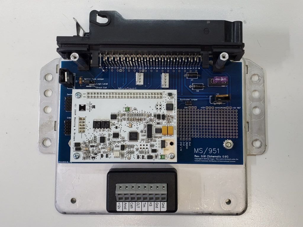
Based on the fully-built MicroSquirt module (like odonnell’s project)
Support for a modest set of engine management features, including:
Batch or semi-sequential injector firing using the stock wiring configuration
Stock coil/distributor or wasted spark
Up to 2 engine position / speed sensor inputs
Speed/density air metering, with MAP sensor integrated into the ECU
Knock detection (via KnockSenseMS)
Boost control
Wide-band O2 sensor support
Stock ICV support
Easily integrated into the existing wiring harness with simple, reversible modifications.
Expansion options for additional sensor inputs (oil temp, EGT, etc.).
Clean physical installation in the standard DME location, with no “rat’s nest” of wires inside or outside the ECU.
Easy access for tuning, with a physically and electrically robust connection.
External CAN bus access, for adding things like gauges, dashboards and more sensors.
Unified proto-board design, with option to produce a custom PCB at a later point.
DIY and budget friendly, emphasising low-cost or repurposed components.
Nothing here will be radically innovative as compared to other builds. But my hope is to end up with a system that is clean and reliable, and in the process, push myself to better understand the workings of engine management systems. I’ve never done this before, so bear with me as I learn.
I also hope that the project will be helpful to others. To that end, everything I produce, including any code, board layouts or documentation, will be openly available (including for commercial use, should anyone be so inclined).
Finally, I should note that, prior to starting this project, I undertook a complete rebuild of my engine wiring harness. The new harness remains compatible with the stock DME/KLR, but I incorporated a number of changes in anticipation of my move to a standalone system, such as adding extra wires for new sensors. What this means is that, for some parts of this project, the details of the wiring will be unique to my car. That said, nothing within the ECU unit itself will be specific to my wiring harness. And as I go along I will try to point how one could achieve the same results without doing an extensive harness rebuild.
My apologies for the radio silence on this. I regret to say that there has been effectively no progress on this for the past year, but I hope to change that now.
At the risk of boring everyone with the details, last year I was presented with an opportunity to take a technology I've built over the last decade and elevate it a level of industry-wide prominence. I worked my *** off for most of the year trying to make that happen, to the point of dropping pretty much everything else in my life. However an overall anti-consumer climate in the industry (IoT), coupled with malicious internal politics at the place I worked (Google), ultimately led me to abandon the effort in disgust.
After all that fell apart I decided it was time to retire. I now have plenty of time to work on projects like this. However, because my job involved embedded systems, I've been pretty burnt out on the whole area, and thus reluctant to jump back into what is essentially another embedded system. I think I'm getting over myself now, so I'm going to try easing back into things.
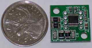
To that end, I did make another rev of the PCB to accommodate a broader range of harness connectors. Over the next week I plan on assembling the system using the new PCB and doing some initial bench testing. I'll try to keep this thread updated with my progress.
Assembling the board revealed a few problems that need to be ironed out. The biggest one is that the footprints for the transistors are reversed, meaning they aren't oriented properly relative to the heat sinks. Easy enough to fix. Most of the other issues involve clearances between parts, but these are all minor.
One feature I plan on adding in the next rev is an easier way to power the board when its out of the car. For safety's sake I probably wont make this accessible without removing the cover.
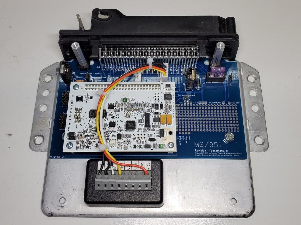
Spun another rev of the board to correct the errors that I found. (It really is amazing how fast you can get a PCB nowadays, for very little money).
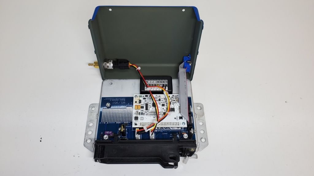
I'm pretty confident in the design now, so I decided to dub this Revision 1. I got the KnockSense mounted to the bottom plate and made up a harness to connect it to the main board.
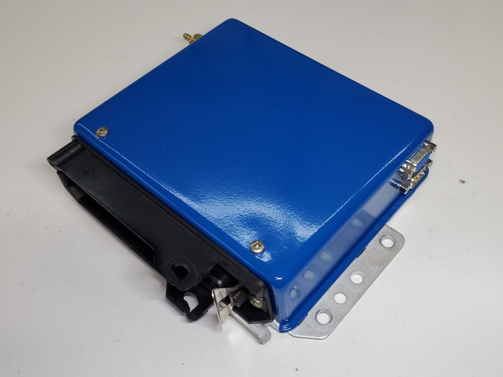
I cut holes in the cover for the serial and CAN connectors, the internal MAP sensor and the cover screws. I used a bit of putty stuck to the underside of the cover to properly locate the holes for the retaining screws. I have to say, I'm pretty pleased with how the cover attachment worked out. Super simple design and very easy to open up when you need to.
I cleaned up the cover and shot it with a bit of paint to give it a bit more of a professional look.
The only thing left to do on the ECU itself is to build the harness for the internal MAP sensor. Parts for that should arrive on Monday. After that I have work to do on the engine harness, and mounts for the IAT and crank sensors. Hopefully I can get to the point of starting it in the next few weeks.
For anyone still following along, I've been working on a bracket for a front mount crank position sensor. Details on the design can be found here: Front crank sensor mount
Meanwhile, I've completed the internals of the ECU:
Jay, I love what you’ve done here. You’ve got skills I wish I had, it definitely would have made my Microsquirt build go faster/better. I opted to use the same KnockSenseMS unit for my build as well but I haven’t gotten a chance to tune it yet. I was very satisfied with the communication and ease of use though, it couldn’t be simpler!
What made you settle on a front-mount crank trigger wheel? I originally went down that road and ordered a 36-1 wheel from GoingSuperFast.com but eventually decided to go with a TTV 60-2 flywheel and reuse the stock sensor on a 968 sensor mount. I liked the idea of being able to replace the parts down the road without a spreadsheet of alternate part numbers so I could remember what I ordered. If you stick with a front mount trigger wheel, shoot me a PM and I’ll send you an offset spacer for the power steering pulley so that it clears the thicker alternator pulley.
I’m glad to see you’re making some traction, I finally finished my replacement ECU harness and got it mounted into the car. I was impressed with myself, only one error and it was an incorrectly pinned TPS. Very easy to fix and when I traced my steps back, I realized I used the pin out from a 944 NA.
Thanks, Aaron! I have to admit I didn't look too closely at the TTV flywheel. On the face of it it seems like a pretty good solution, albeit not particularly cheap. However, after being forced to change out the brand new clutch on my newly rebuilt and re-installed engine, I am extremely loath to take the whole thing apart again!
Thank you for the offer of the spacer. I have deleted the power steering on my car, so I'm running without the PS pulley. I was wondering about the alignment of the alternator belt, though. I'm running a Quest alternator in the stock position, using the stock alternator bracket, but with the A/C deleted. I spent some time adjusting the position of the new alternator to line up properly with the crank pulley. But now of course I've just offset the two by an additional 3mm. Haven't decided whether I need to go back and revisit that. I assume you just left the alignment as is?
Well, I’ve discovered another bug in the design of my board. As it turns out, I’ve been somewhat confused about how the MicroSquirt works. The MicroSquirt module (which differs from the assembled MicroSquirt ECU) has two tach input circuits, one for a crank sensor (VRIN+) and one for a cam sensor (VRIN2+). The cam circuit is designed in such a way that it can accommodate either a VR sensor or a hall sensor. In designing my board, I made the mistake of assuming that the VRIN+ circuit also worked this way. Unfortunately the VRIN+ input requires a true zero-crossing signal (AC), as produced by a VR sensor. Because a hall sensor only produces a DC signal (e.g. 0-5V), it isn’t compatible.
There are various solutions people have developed to work around this. One possibility is to add a conditioning circuit which translates the output of the hall sensor to look like a VR sensor. However this means adding a number of additional components to the design, which I’d rather avoid.
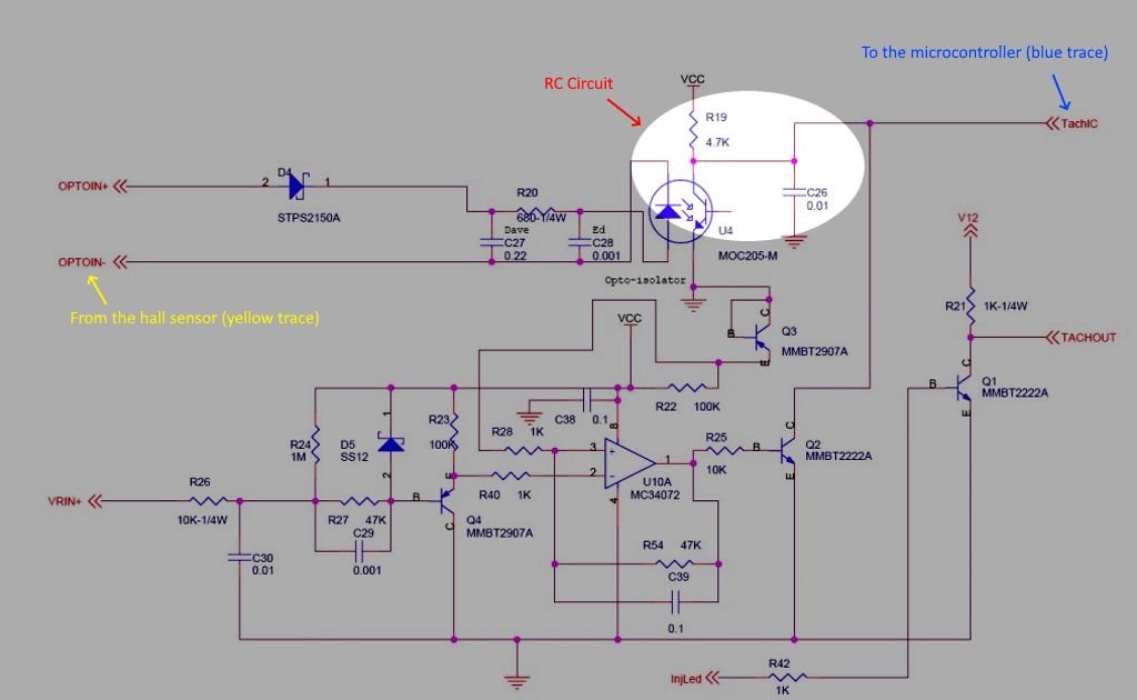
Another solution is to use the OPTO IN +/- inputs. These inputs pass the signal through an opto-isolator before delivering it to the crank tach input pin on the microcontroller. (This is the same pin that the VRIN+ circuit connects to). Somewhat conveniently, because my hall sensor does _not_ have a built-in pull-up resistor, it can be connected to the OPTO IN - input without adding an external pull-up resistor. The OPTO IN + input is then connected to +5V. In this mode, the open-collector transistor in the hall sensor acts as low-side switch to trigger the opto-isolator and deliver the signal to the microcontroller.
Now, there is some controversy about using the OPTO IN circuit for reading a trigger wheel. Some people say it wasn’t meant for that (this seems to be true) and that you should never do it (dubious). However based on my testing, I’ve concluded that it should work given the parameters of my build.
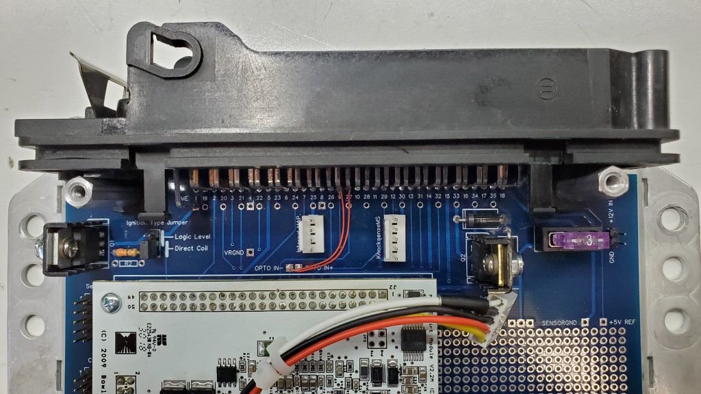
Hacking my board to use the OPTO IN circuit was short matter of cutting a trace and adding a couple jumpers:
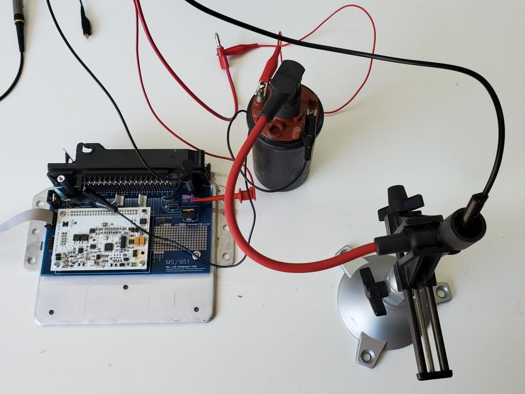
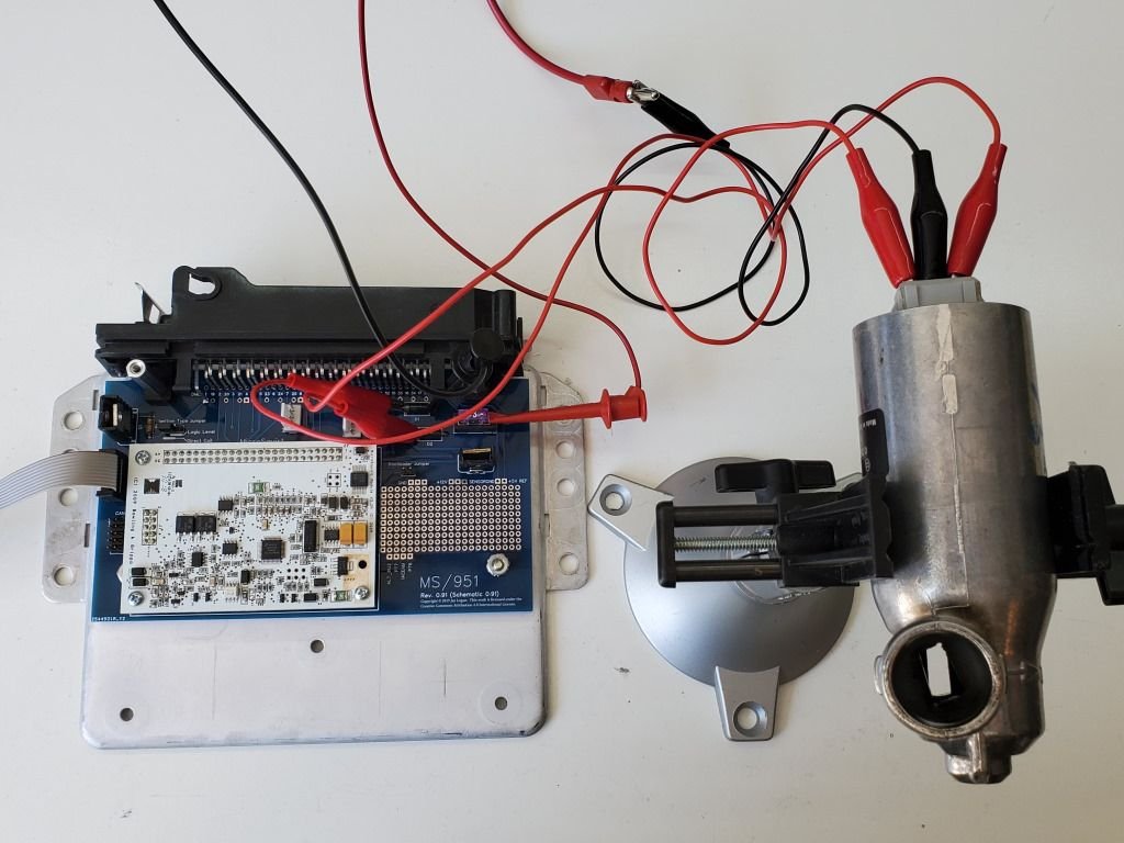
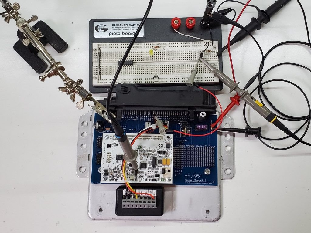
To bench test the change, I mocked up the output from the hall sensor using a frequency generator driving a NPN transistor in open collector mode.
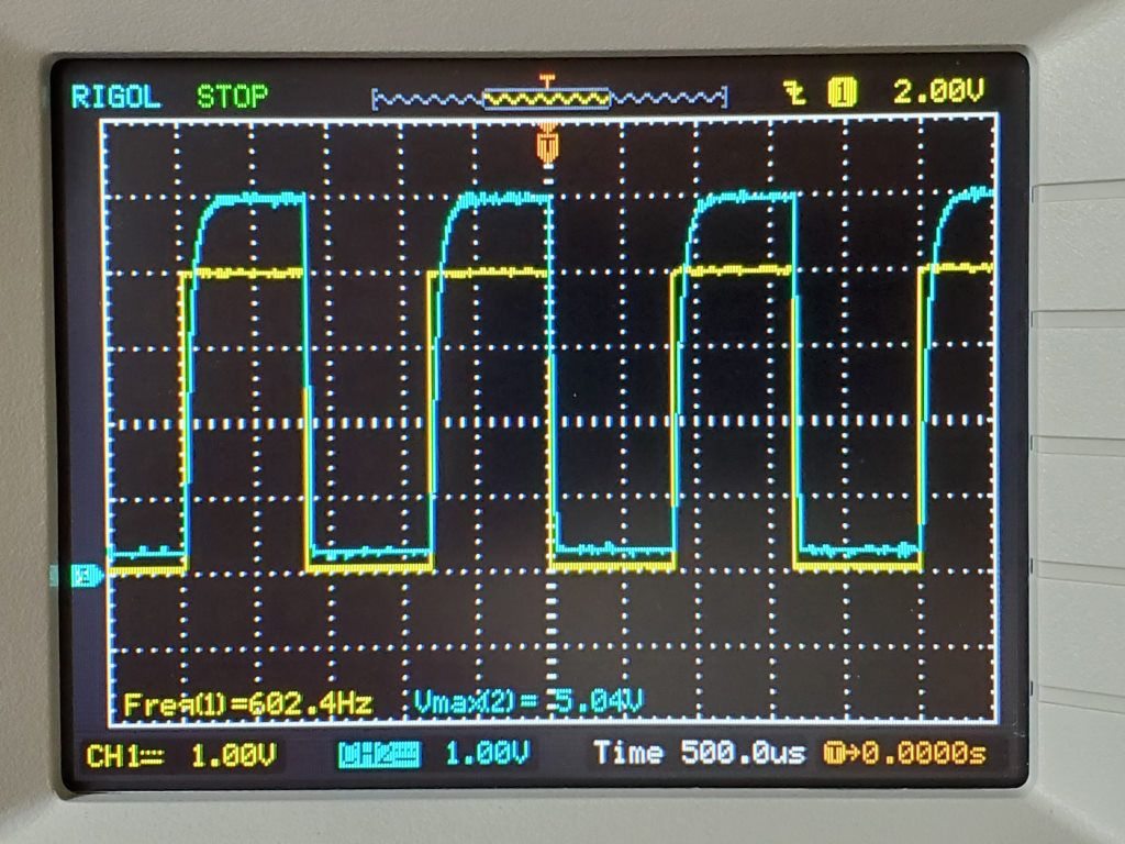
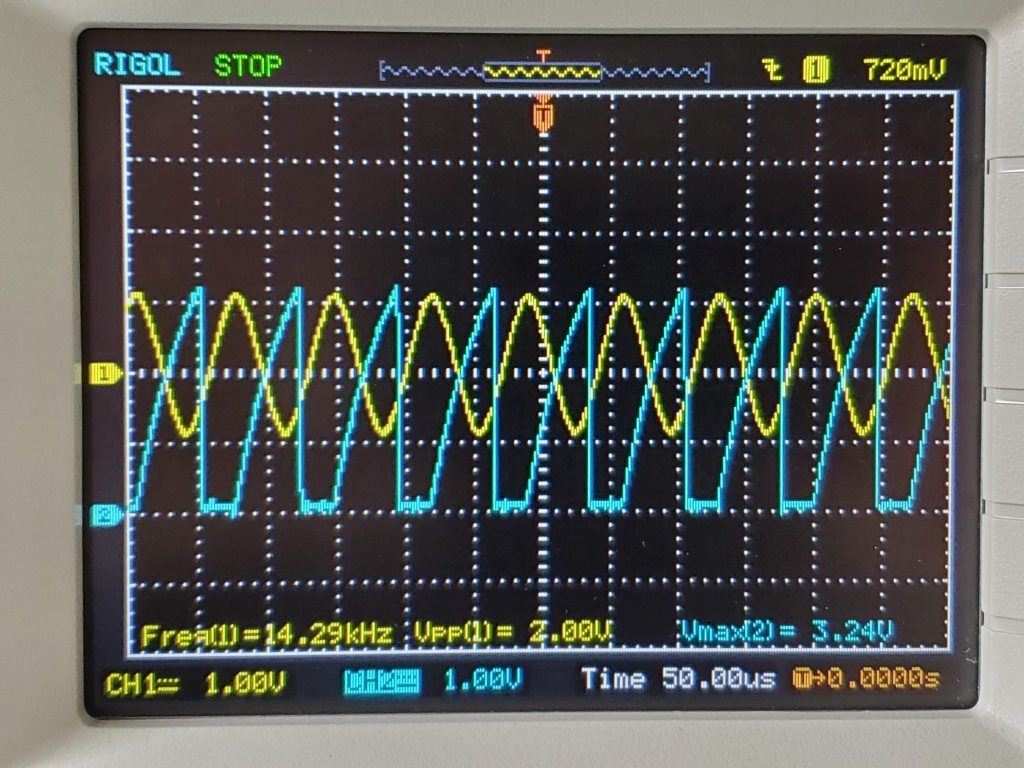
I then measured the signal seen by the microcontroller on the MicroSquirt. In this image, yellow is the simulated hall sensor output, and blue is the input signal to the uC pin.
This trace showed the new circuit to be working roughly as expected.
One interesting thing to note here is the curvature on the rising edge of the uC input. This I believe is the heart of the controversy surrounding OPTO IN, and the reason why we can’t use MicroSquirt with the stock 951 speed sensor and flywheel. More details on this in a subsequent post...
In my previous post, the oscilloscope trace was taken with the signal generator set to roughly 600 Hz. This is equivalent to the engine running at 1000 RPM using a 36-1 trigger wheel, i.e.: 1000 RPM x 36 teeth/rev / 60 seconds/minute = 600 teeth / second, or 600 Hz. At this speed, the input to the microcontroller (blue trace) is roughly a 5V square wave, with a little bit of curvature on the leading edge. This curvature is due to an RC (resistor-capacitor) filter built-in to the MicroSquirt and common to both the VRIN+ input and the OPTO IN input (but not the VRIN2+ input). The RC circuit effectively limits how fast the signal can rise.
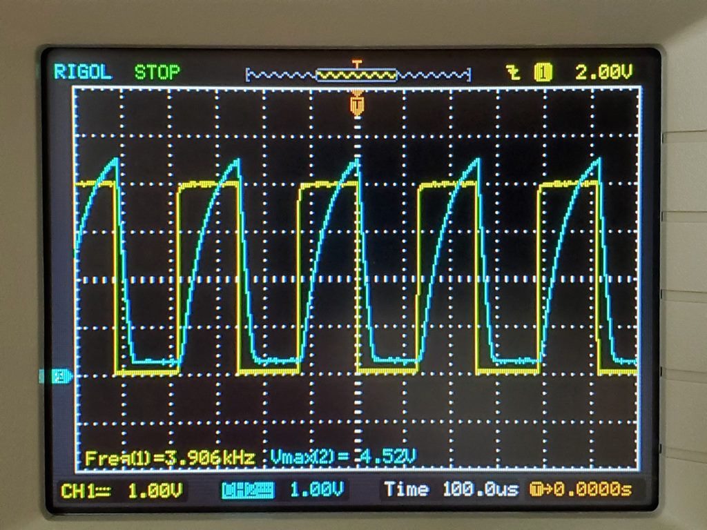
At redline (6500) the tooth rate is 3900 teeth/sec (3.9 kHz). As the following trace shows, at this speed the signal to the uC now reaches a max voltage of only 4.56V, and is predominantly saw toothed in shape. Again, this is due to the behavior of the RC filter circuit.
For the microcontroller to detect the tach signal, the input to the uC pin must transition from a low voltage level to a high level and then back again. On the MicroSquirt, the input voltage is required to reach at least 3.25V in order to be considered “high”. Based on the above trace, the signal at redline easily exceeds this voltage, and thus should be detected correctly (again, using a 36-1 wheel).
Seeing how pointed the signal is at the top, I wondered for a moment whether the duration of the signal above the 3.25V level was long enough to be detected by the microcontroller. However, based on my understanding of the clock speed of the MicroSquirt (bus clock = 24Mhz), I believe this isn’t a problem, as the processor should detect the low-to-high transition in less than a microsecond (specifically, 4 bus cycles or 167 ns).
Based on this, I’m reasonably confident that I can get away with using the OPTO IN input with my hall sensor and a 36-1 wheel. Looking at the curves, I’m inclined to configure MicroSquirt to trigger on the falling edge of the tach signal, simply because it’s cleaner. However I’m not certain this will make any difference in practice.
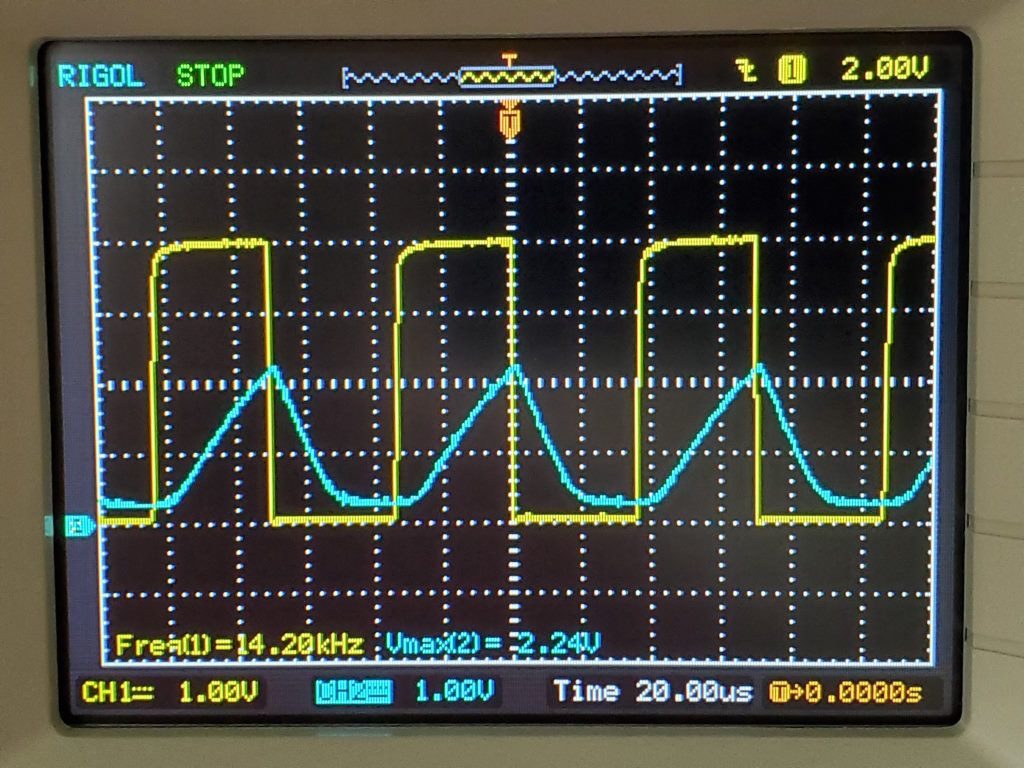
Given the analysis in my previous post, it’s interesting to speculate what the signal might look like if one were to use the stock flywheel with 132 teeth. At redline, this would yield 14300 teeth / second. Presuming the use of a hall sensor connected to the OPTO IN input, the signal might look like this:
As you can see, the signal to the microcontroller is only 2.24V in this case, likely far too low for it to be recognized.
But what if one used stock the VR speed sensor connected to the VRIN+ input instead of a hall sensor? To simulate this, I drove the VRIN+ input with a 2V peak-to-peak AC signal (mimicking a VR sensor) and got this:
Interestingly, here the uC signal voltage is considerably higher. This is because the “on” time of the VRIN+ circuit (the time within each cycle during which the capacitor is charging) is longer as compared to the OPTO IN circuit. But still, even in this configuration, the peak voltage is only a marginal 3.24V.
Thus, it appears that the RC filter circuit in the MicroSquirt makes it difficult or impossible to get a reliable tach signal using the stock 951 speed sensor configuration. As it turns out, other people have run into this same limitation on other vehicles. And interestingly, some have devised a work-around that involves making a small modification to the MicroSquirt. At some point I will test this modification to see if I can get my car running on the stock sensors.
Well, I’ve discovered another bug in the design of my board. As it turns out, I’ve been somewhat confused about how the MicroSquirt works. The MicroSquirt module (which differs from the assembled MicroSquirt ECU) has two tach input circuits, one for a crank sensor (VRIN+) and one for a cam sensor (VRIN2+). The cam circuit is designed in such a way that it can accommodate either a VR sensor or a hall sensor. In designing my board, I made the mistake of assuming that the VRIN+ circuit also worked this way. Unfortunately the VRIN+ input requires a true zero-crossing signal (AC), as produced by a VR sensor. Because a hall sensor only produces a DC signal (e.g. 0-5V), it isn’t compatible.
There are various solutions people have developed to work around this. One possibility is to add a conditioning circuit which translates the output of the hall sensor to look like a VR sensor. However this means adding a number of additional components to the design, which I’d rather avoid.
Another solution is to use the OPTO IN +/- inputs. These inputs pass the signal through an opto-isolator before delivering it to the crank tach input pin on the microcontroller. (This is the same pin that the VRIN+ circuit connects to). Somewhat conveniently, because my hall sensor does _not_ have a built-in pull-up resistor, it can be connected to the OPTO IN - input without adding an external pull-up resistor. The OPTO IN + input is then connected to +5V. In this mode, the open-collector transistor in the hall sensor acts as low-side switch to trigger the opto-isolator and deliver the signal to the microcontroller.
Now, there is some controversy about using the OPTO IN circuit for reading a trigger wheel. Some people say it wasn’t meant for that (this seems to be true) and that you should never do it (dubious). However based on my testing, I’ve concluded that it should work given the parameters of my build.
Hacking my board to use the OPTO IN circuit was short matter of cutting a trace and adding a couple jumpers:
To bench test the change, I mocked up the output from the hall sensor using a frequency generator driving a NPN transistor in open collector mode.
I then measured the signal seen by the microcontroller on the MicroSquirt. In this image, yellow is the simulated hall sensor output, and blue is the input signal to the uC pin.
This trace showed the new circuit to be working roughly as expected.
One interesting thing to note here is the curvature on the rising edge of the uC input. This I believe is the heart of the controversy surrounding OPTO IN, and the reason why we can’t use MicroSquirt with the stock 951 speed sensor and flywheel. More details on this in a subsequent post...
http://jbperf.com/dual_VR/v2_1.html Dual VR Conditioner Board V2.1
Small enough to solder onto the proto area on your board
Also, the micro squirt doesn't have the code to run 951 or non S2 flywheel set up MS3 has the code called Tri-Tach in tuner studio
As it turns out, the problem I noticed wasn't really a big deal. I had meant to use a different, more readily available fuse holder, but I forgot to adjust the board layout. Since then I found a source for the original fuse holder and bought a bunch.
Perhaps the bigger issue is the choice of harness connector. I've been using the connector from a DME that is used in early '90s Saabs and Volvos. The connector pins form a single row where the pins interface with the PCB (see pic above). As it turns out, this style seems to have had a fairly narrow production lifetime, in between two other styles that use staggered pins. This has made it harder than I anticipated to source the connector. I'm pretty sure I can modify the PCB layout to accommodate both styles of connector, which would be an obvious upgrade to the design.
The other issue I've run into is mounting in the original case. Again, there's lots of seemingly unnecessary variance in the design of the base-plate which means that my board mounts correctly only in select DME cases. This is a bigger issue in my opinion, as one of my goals was for this project to be easy to construct from available parts. Because of this I spent some time sourcing a generic case to use as an alternative. I've found a good candidate, but as one might imagine, there's lots of mechanical details to be worked out that are all solved with the Bosch case.
I'm not familiar with the 924 at all. However, at least for the 951 and the 944 NAs, it's very easy to take the harness connector apart and re-order the pins. This requires no soldering and is completely reversible. So my guess is you should be able to adapt the 924 harness as well.

 05-17-2020, 09:16 PM