When you click on links to various merchants on this site and make a purchase, this can result in this site earning a commission. Affiliate programs and affiliations include, but are not limited to, the eBay Partner Network.
Hi guys, haven't been active on here that much recently. My current project is building a plug and play ECU that offers the functionality of a standalone ECU without breaking the bank. This is nothing new - VEMS has been available for a while. I don't claim that this ECU is any better than VEMS, but this costs around $500 to make. I haven't finished it yet, I will update the running costs as I go, but this thread serves to document the project. Note that a lot of my hyperlinks are embedded into my text as links - sometimes ads will do that to trick you into clicking them, so hover your mouse over the link to make sure it's not one of those automated VigLink advertisements.
My 944 NA has been running perfectly on Megasquirt for almost 4 years, the build thread is here. I chose the MicroSquirt Module as the heart of this ECU because I'm familiar with the functionality and it's a great value for the money. This ECU is going into an NA 944 that has been turbocharged using a homemade kit, so it's designed to utilize as much of the factory setup as possible without being utterly useless as a standalone. I considered options such as Speeduino but the MS is home turf for me without being that much more expensive. This ECU would work on a NA 944 or a 951, provided that the end user configures the settings correctly.
So without further ado, here is my recipe. I may edit this post in the future to provide more detail, but none of this stuff is hard to find. This is for the components inside the ECU, I will cover the outside parts at a later time.
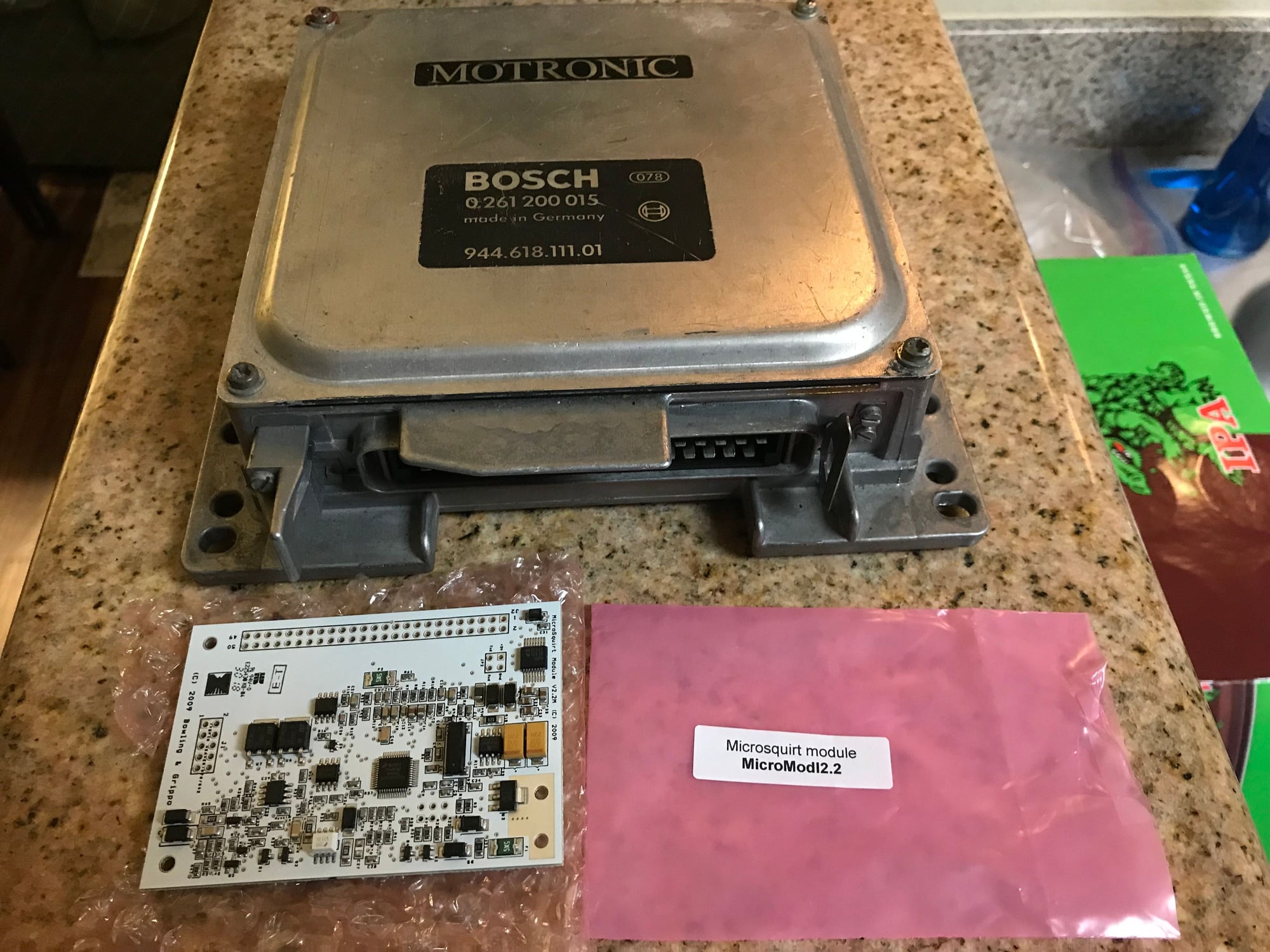
Donor/dead DME. I am using an early 944 DME, this part should cost you little to nothing if it's dead. I like the early DME because of its construction, it's very solid and the case is thicker. You will see later on in the build how the case features are used to accommodate internal components.
MicroSquirt Module. I got mine from DIYAutoTune for around $250 on sale. This is the majority of the cost. It comes as just a SMD board, no harness and no frills. However, it offers equivalent functionality of the cased MicroSquirt unit once it's adapted to the rest of the ECU. Think of it as the brain. Dougs951S has been using the Micro on his modified 951 for years and I have been running it on my NA - it's more than capable of delivering the goods for a boosted or naturally aspirated car.
General electronic supplies. These are dirt cheap:
The Micro utilizes standard 0.1" spaced headers (2.54mm). The primary input/output header is 2 rows of 25 pins, so you can use AMP 7-534206-5. I would recommend getting some other header pins as well, you can snap them apart to make them the right size as you need them.
Get some good rosin core leaded solder and make sure you have a half decent soldering iron. I got my Weller soldering station for around $40 shipped.
Desoldering wick. When you **** up, you can easily soak up the solder from the board without getting it everywhere.
Jumper wires. These connect the header pins to wherever they need to go. I got
but so far, am less than impressed by the quality. They'll work for this prototype ECU but I would look around for more options. Just make sure they are designed for the 0.1" pin spacing and will work with the headers you got. Get male-male and male-female.
Heat shrink for general use. Adhesive lined is best, don't get the crappy cheap kind. Kits with a variety of sizes aren't expensive.
Board stand-offs. The Micro board has 4x mounting holes, each is 1/8" diameter. I got
out of convenience, they are 11mm effective height and have 2.5mm diameter fasteners. Works perfectly fine. These will mount your MS to the DME casing and provide heatsinking for the 5v regulator.
Some sort of 5A fuse setup. The MS should ideally be fused against its 12v power supply, to insure against a wiring issue (let's be honest, as DIYers this happens). Get something small that you can wire inline to a wire, it will go inside the DME case.
MAP sensor to go inside the DME housing. This is optional, as you can easily use an external MAP sensor from a GM vehicle or etc. But for maximum plug-and-play points, I am using a Freescale MPX4250 2.5 bar MAP sensor mounted internally. If you search around, you will see these for under $20. You may also consider a bulkhead to pass the nipple through the case. I'm not sure if I'll need this or not, but for $4 I got it. Obviously you will need some appropriate vacuum hose to run from your DME location to the engine bay. I would recommend teeing into the vac lines that go the FPR and damper. I did this on my 944 and it works fine, and it's very straightforward. Keep in mind you will need a physical 3-way tee for the engine bay end, the OEM hard plastic lines will probably require a rubber tee that elastically stretches over the outside of the lines.
Provisions for connectivity. The pre-MS3 boards (Micro is based on MS2) rely on serial communication to your tuning laptop. However, there are countless products that can adapt this to simple USB. You will find a 4-pin square header on the Micro labeled Vref, GND, Rx, and Tx. The latter 2 are serial communications, and the GND is serial ground. These pins also exist on the main 2x25 header. More on this later, but there are hundreds of small chips that can turn these into a USB connector. I will post a link when I have confirmed one that will work with no headaches. Worst case scenario, you can wire up a serial (RS232) connector and use a generic USB adapter. I use the Aten U232 for my NA and it works flawlessly.
A driver to fire the ignition coil. The Micro comes with 2 drivers, but they are low-power "logic level" signals. This is fine for coils which feature an internal igniter, but the factory 944 coil requires an external driver that incorporates dwell time requirements and supplies all of the current needed to charge it up. I used LS1 coils on my 944 as these are natively compatible with the Micro. But to make this plug and play, I am choosing a BIP373 transistor to adapt the MS coil commands into a signal equivalent to what the DME would have originally sent the coil.
As much as I would love to have this be a giant write up all in one shot, I'm still in the process of building the board. I'll keep this thread active with my progress. I'd like to keep this blended in with reader feedback and questions, instead of constantly updating the original post. To foreshadow my next post, I'll be discussing the reason that most standalone installations fail or never get off the ground for the 944.... speed and reference sensors. Without crank signal, nothing happens. Wiring information and pin assignments in a later post.
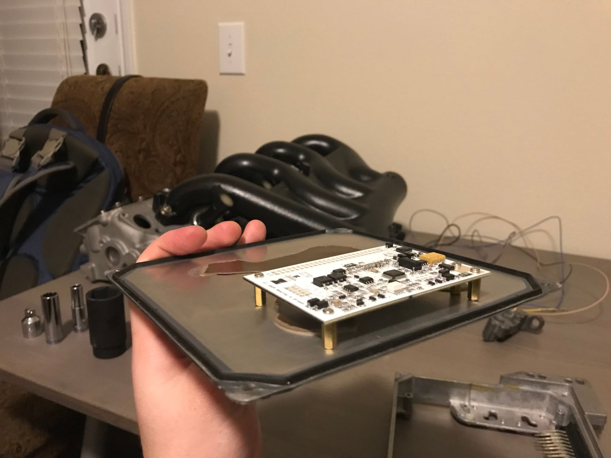
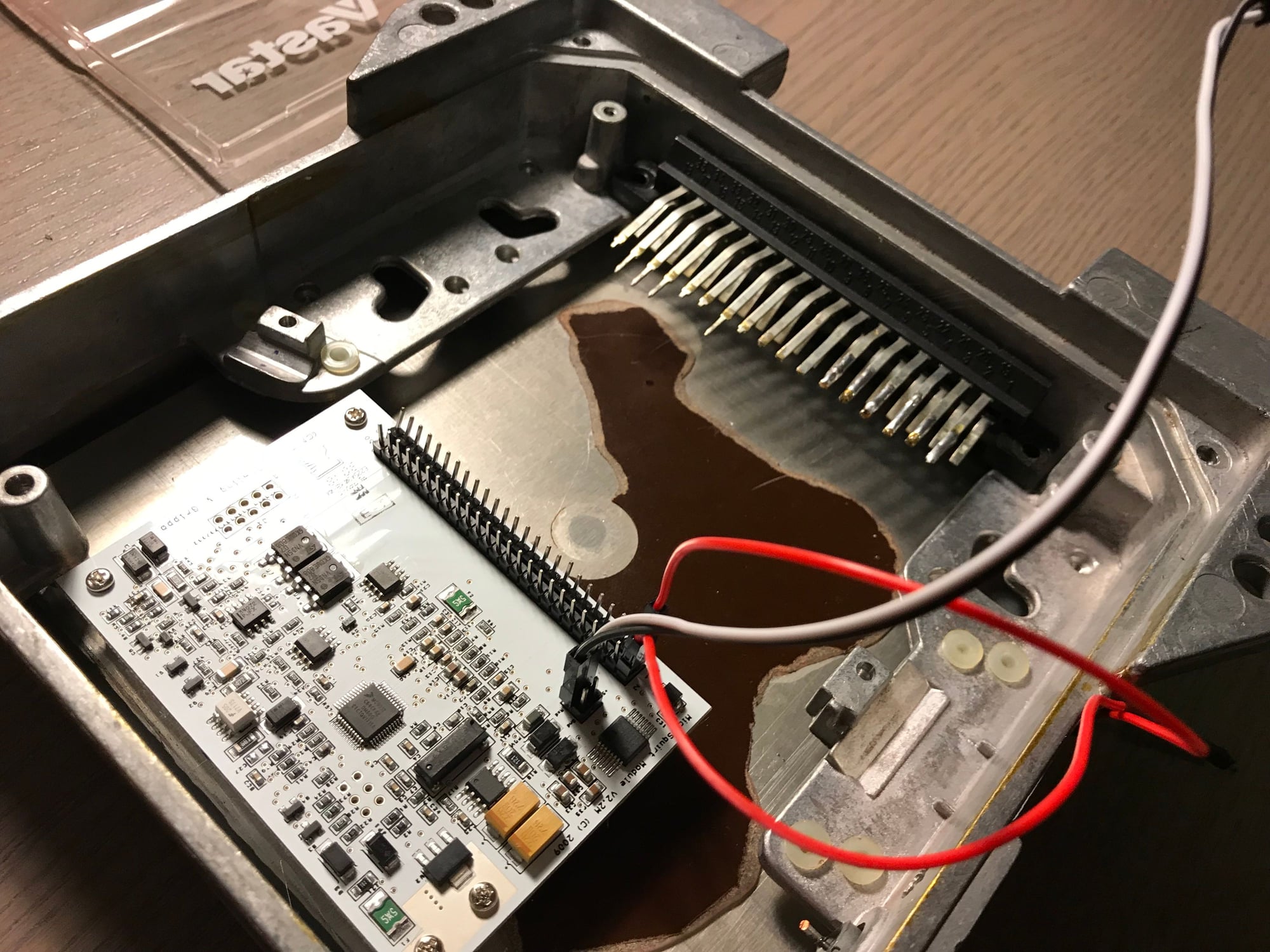
But for the meantime, here are some pictures of the MicroSquirt module mounted to the DME case. I soldered on the headers, one was a bit crooked because it shifted when I was soldering the first pin (lesson learned but this won't pose any problems). Next time I'll temporarily fasten it before starting. For the board mounting holes, I traced them onto a piece of paper and then used that template to mark the bottom plate of the early DME case. Then it's a simple matter of drilling the holes and installing the standoffs mentioned previously.
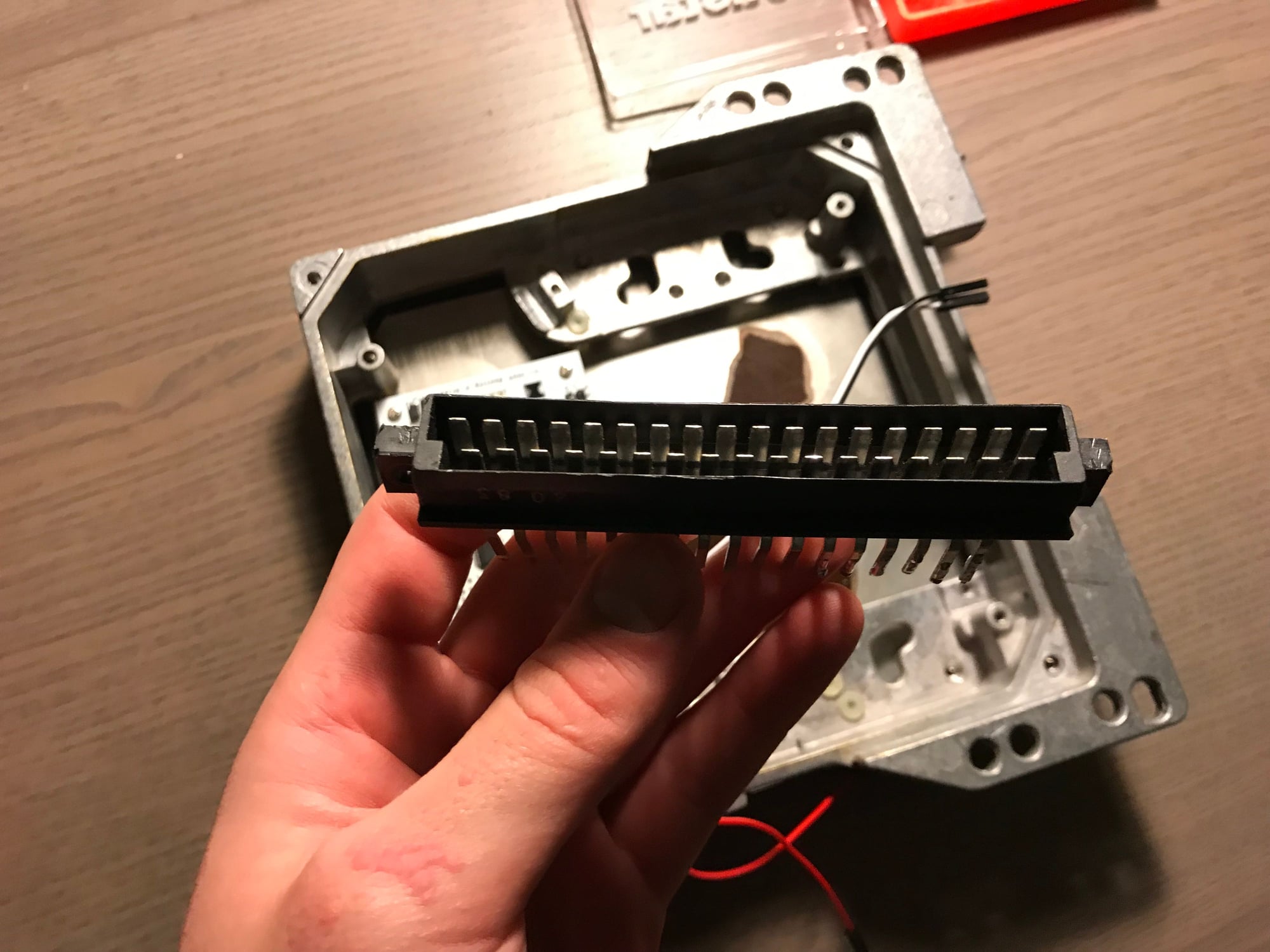
I also cut the DME main connector off the DME circuitboard with a Dremel tool. This will adapt the MS wiring inside the DME case to the factory wiring harness. I also tried to peel off the brown insulator sheet on the DME cover on which I mounted the MS. As you can see this was a write off, the glue is very strong and not worth the hassle. I just picked my 4 mounting hole locations to be in areas where the standoffs would be directly though metal with no insulating layer (although in the pictures it doesn't look like it). This is because the 2x mounting holes that are close together (on the same side) also serve as heatsink paths for the onboard voltage regulator. I wanted the brass standoffs to act like heat conduits to the DME housing.
in the Houston area as well and would like to see this happen, there needs to be a good option for us early 944 guys for a plug and play ECM.
Nice, what area? If you're interested in being a test subject, it would be cool to test this ECU on an early 944. Mine doesn't have a stock wiring harness or sensors anymore. The car this is going into is a late 944, although it will be offered as part of an aftermarket turbo kit if it works out.
I'm in the Mont Belvieu/Baytown area. My car is 100% stock except the motor is out of a late '85 since the original motor had a blown #4 cylinder thanks to jackleg mechanics. I picked up the engine it has now from a Harvey flood car, put new gaskets on it stuffed it in and she has ran great. I don't mind being a test subject, I've read a lot of your other work on the MS system and you seem to have your head on straight with that stuff. I've also looked at Ftech stuff but then I would have to buy a late DME and AFM just to have the DME gutted and be around $1K into it.
+Subscribed
Hey Micheal here's another idea for connectivity is a HC-05 Bluetooth board.
I did it on my build it a has Bluetooth and RS232 USB board with a 2 way switch that I could direct link to my laptop or hook up to my phone through BT to monitor
You just cant do both at the same time I guess unless one is a read only (just thought about that)
Also don't hook the RS232 power to the board unless you disable the 5 or 3.3v from the computer because basically you will be putting 8 to 10v to the CPU n it doesn't like that..
I thought about doing the very same thing when doing my original MS II build not sure a MS III and my O2 sensor driver board would still fit in the Stock ECU case..
Good work as usual you were my inspiration for my original MS II when my original ECU died.
I'm in the Mont Belvieu/Baytown area. My car is 100% stock except the motor is out of a late '85 since the original motor had a blown #4 cylinder thanks to jackleg mechanics. I picked up the engine it has now from a Harvey flood car, put new gaskets on it stuffed it in and she has ran great. I don't mind being a test subject, I've read a lot of your other work on the MS system and you seem to have your head on straight with that stuff. I've also looked at Ftech stuff but then I would have to buy a late DME and AFM just to have the DME gutted and be around $1K into it.
Good deal! I'll drop a line when I'm getting close to the testing phase. I'll provide beer and any spare early NA parts I don't need that you want
Originally Posted by Dwizle
+Subscribed
Hey Micheal here's another idea for connectivity is a HC-05 Bluetooth board.
I did it on my build it a has Bluetooth and RS232 USB board with a 2 way switch that I could direct link to my laptop or hook up to my phone through BT to monitor
You just cant do both at the same time I guess unless one is a read only (just thought about that)
Also don't hook the RS232 power to the board unless you disable the 5 or 3.3v from the computer because basically you will be putting 8 to 10v to the CPU n it doesn't like that..
I thought about doing the very same thing when doing my original MS II build not sure a MS III and my O2 sensor driver board would still fit in the Stock ECU case..
Good work as usual you were my inspiration for my original MS II when my original ECU died.
Hi Dwizle, do you have any more info on that 2-in-1 board? I actually bought an HC-05 a few months ago for my 951's MS3Pro system that I was going to use for this. But my main concern is that if I needed a physical connection for some reason I would have to be creative with connections, and this is all supposed to be hidden in the DME case. I also read about issues with the baud rates (even after programming it to be 115200 some people still have problems) and flaky port scanning leading to TunerStudio not always finding the virtual COM port. But I'm all ears if you have a solution. Thanks!
Sounds good, PM me on here and I�ll shot you my number. I haven�t seen another 944 since I got mine back in June. These cars are definitely not belly buttons.
The topic of this evening's update is the crank trigger. As stated before, this is a common problem for standalones used in 944s.
But first, some background for the uninitiated. The root cause of this dilemma is that the starter ring gear is used to provide the speed signal to the ECU so that it knows how fast the engine is spinning. For even primitive EFI, this is essential information so that the proper amount of fuel can be injected per the tune. It's also essential so the ECU knows the appropriate time to fire the ignition coil(s) in the cycle. The stock DME also uses a 2nd sensor, called the reference sensor, that reads a single stud protruding from the flywheel. This tells the computer the position of the crankshaft. Because the ring gear has identical teeth all the way around, there is no way for the ECU to know the crank position/angle by only using the speed sensor - it can only tell you how fast it's spinning.
The problem is ultimately that the number of teeth on the ring gear is quite high. At 6000 rpm, there are 130 or 132 teeth to count (NA and 951 respectively). It turns out that this adds up pretty quickly for a lot of ECUs and most people run into problems as the processor can't keep up with the constant calculations as the signals come in. The stock DME accomplished this by using a bespoke S100 chip, which processes the 2 signals into something the DME can actually use. Without hardware like this, it's not always straightforward to make them work. I looked at using S100 chips from core DMEs but I'm not an electrical engineer and promptly gave up.
At the time of this writing, these are your options for using the stock speed and reference sensors over the bellhousing:
Buy a VEMS or other EMS because it already has native support for the 130+1 (NA) and 132+1 (951) signals. Most expensive option, and not a solution if you're considering an ECU like this DIY one.
Purchase a 60-2 pattern flywheel and only use the reference sensor. For an NA, a 944S or S2 part is a direct fit. For a 951, the TTV 60-2 flywheel is great. I have one for my 951 - expect to spend $400-600 including customs. The process of changing a flywheel is not trivial.
Use tri-tach mode (or equivalent, if not Megasquirt). This is an experimental feature on MS3 and later Megasquirts. It was designed for Audis which have 2 crank sensors and a cam sensor. The crank sensors are very similar to the 944 as far as using the ring gear plus a TDC reference stud on the flywheel. Unfortunately I haven't been able to find any success stories after reading every forum post I could turn up. This also isn't supported on MS2 and earlier, and the Microsquirt unit I'm using is based on MS2.
This is a fringe solution, but one could build a divide-by-13 hardware divider if using a 130 tooth ring gear. I have no idea how to build something like that. The Megasquirt code requires that the value of 3600 / N is always an integer (no decimals), where "N" is the number of teeth. This number must also be divisible by the number of cylinders to yield an integer. Dividing 130 teeth by 2 or 5 is something you can do with an off-the-shelf part, but does not satisfy the requirements of the code.
You can always adapt a trigger wheel to the front of the crank, or equivalent. The only one that seems to be worth the bother is the Clewitt Engineering unit, $400. I did a budget 36-1 wheel on my NA which has always worked just fine but it's not the first option for folks who want a simple and cheap path to a standalone ECU. So I'm throwing this one out too.
After all of this discussion, I have been led to a solution which actually works, and will be used for my prototype ECU. Because the reference sensor is not the problem, it will stay. But the speed sensor is replaced with a cam sensor which reads the teeth on the cam pulley for the timing belt drive. Think of this as a miniature version of the ring gear - just a sensor reading some teeth to figure out fast something is spinning. This gear has 40 teeth, and turns at half the speed of the crankshaft. The 40 teeth satisfy the code requirements listed in the last bullet point above, and will easily be accommodated by even the most basic standalone ECU.
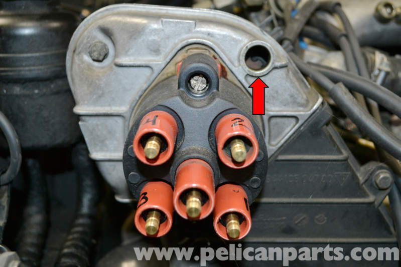
So for implementation: recall the inspection window on the distributor housing:
The sensor I am using is a generic gear tooth sensor (hall effect). Cherry GS100502, can be found for under $30 shipped. You will also need a 2.4 kOhm resistor. The power wire of the sensor gets switched 12v, and the ground wire goes to your ECU's signal/sensor ground. The signal wire goes to your speed sensor input. The resistor connects at some point along the 12v wire, and tees into your sensor's signal wire to act as a pull-up resistor. I will go into more depth on the wiring later on - this is just to present the concept.
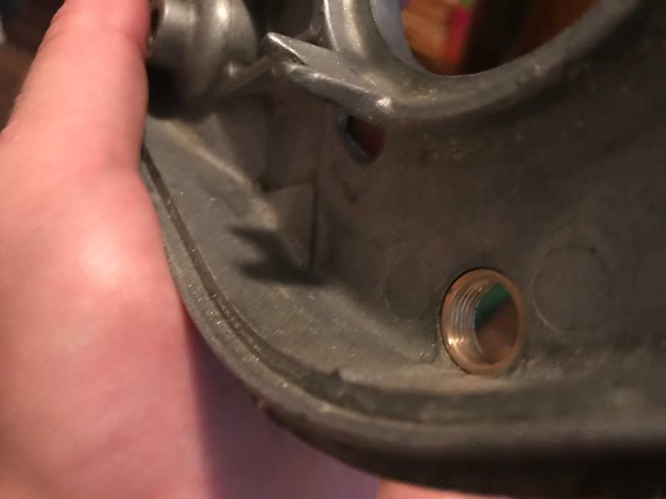
To adapt the sensor, I used an inexpensive brass sleeve from McMaster-Carr, P/N 7815K62. This is a press fit into the inspection hole, as it has a 9/16" outer diameter. Sometimes you just get lucky with metric vs imperial sizes. Some Loctite 680 is recommended to keep it snug - you can use McMaster-Carr P/N 91458A121 to get a 1-time use tube. It's designed for these materials and can even be used if they are oily.
Next, I cut threads in the sleeve with a M12 x 1.00mm tap (readily available online). This is again another case where the imperial size (7/16" inner diameter) ends up working out, as this is spot on for the tap size. Tap all the way through, it's easy to go crooked if you aren't careful. If you're doing it freehand, a trick I learned is to use one of the 2 jam nuts provided with the sensor, and thread it partially up the tap. Start the tap into the sleeve, but just barely. Now thread the nut down until it starts to contact the top of the sleeve, and make sure it's squared up. Back off the nut slightly and cut a few threads - the soft material will cut very easily. Run the nut back down and check again, using it as a guide until you have enough threads to align the non-tapered body of the tap as you go.
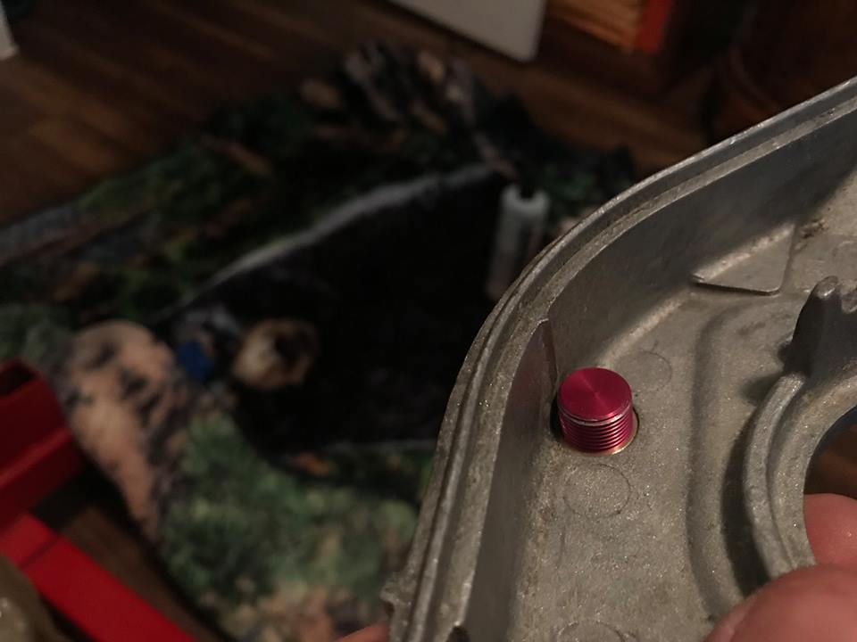
This can theoretically be done without removing any parts from the car but I removed the housing. Clean the inside of the inspection hole sufficiently, and maybe a few seconds of cleaning up with some sandpaper to get any rough edges off. When you're ready, the sleeve should fully bottom out as shown down below. You have to work fast if you use the Loctite, be prepared to encourage it into the bore.
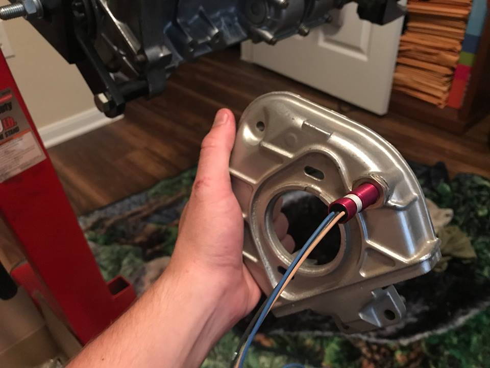
The sensor simply threads in to the sleeve. When it bottomed out and contacted the cam pulley, I backed it off 1.5 turns (1.5mm due to thread pitch) and locked it with one of the supplied jam nuts. This is how you gap the sensor.... pretty easy.
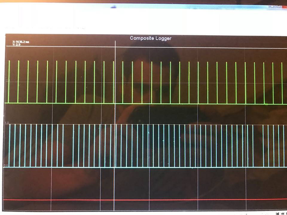
To test this, I set it up on my 944 NA. It has a 36-1 trigger wheel that is used to run the engine normally. The 36-1 trigger wheel is in blue, which is running the engine. Green trace is the 40 tooth cam wheel. The "missing tooth" of the 36-1 wheel shows up after 35 pulses, and 20 teeth register on the green cam signal trace in this timeframe because the cam spins at 1/2 speed.
Hey Michael, your post is very timely! With my project car back on it wheels again, I was just starting to think about what to do for engine management. MS has always been my intention, although I will say the apparent ease of implementation of VEMS has been quite impressive. Still, this is just the sort of DIY project that I like. I'm glad to see renewed enthusiasm from one of the 944 MS pioneers. This makes jumping into MS a no-brainer for me. Thanks for doing this!
One thing that wasn't quite clear from your post--is this intended to be an instructions-only project or are you planning on producing a kit?
Rather than waiting for a kit, I'm thinking I'll just follow along with your updates and try to replicate your build. I'm reasonably competent with soldering and electronics assembly. And I'm happy to provide any feedback that I can.
A little background on my car: I have an '86 951 that's destined to be a track car. Its finally running again after an engine-out rebuild and many upgrades (turbo, exhaust, W/G, fuel pump). The car is currently running a stock 951 ECU, but with an entirely rebuilt wiring harness (image here). The new harness includes upgrades to support MAP/MAF and crank/cam position sensors (currently unused) and a WBO2 (Zt-2). It can also be adapted for sequential injection. My plan was to start simple and add bells and whistles (sequential, maybe COP) later.
So I guess first order of business is, where's the best place to get a dead DME?
Outstanding thread, I like seeing people going outside the box, but also being creative to make an upgrade fit an application using what is in front of them instead of straight to super modified/custom solutions that require extensive skills to reproduce. Using the cam gear port is a very elegant solution, crossing my fingers it works out. Keep at it. Thanks for sharing.
Hey Michael, your post is very timely! With my project car back on it wheels again, I was just starting to think about what to do for engine management. MS has always been my intention, although I will say the apparent ease of implementation of VEMS has been quite impressive. Still, this is just the sort of DIY project that I like. I'm glad to see renewed enthusiasm from one of the 944 MS pioneers. This makes jumping into MS a no-brainer for me. Thanks for doing this!
One thing that wasn't quite clear from your post--is this intended to be an instructions-only project or are you planning on producing a kit?
Rather than waiting for a kit, I'm thinking I'll just follow along with your updates and try to replicate your build. I'm reasonably competent with soldering and electronics assembly. And I'm happy to provide any feedback that I can.
A little background on my car: I have an '86 951 that's destined to be a track car. Its finally running again after an engine-out rebuild and many upgrades (turbo, exhaust, W/G, fuel pump). The car is currently running a stock 951 ECU, but with an entirely rebuilt wiring harness (image here). The new harness includes upgrades to support MAP/MAF and crank/cam position sensors (currently unused) and a WBO2 (Zt-2). It can also be adapted for sequential injection. My plan was to start simple and add bells and whistles (sequential, maybe COP) later.
So I guess first order of business is, where's the best place to get a dead DME?
Man that's a clean looking harness.... nice work. Definitely keep us updated with the progress.
As far as the intent for this ECU, to be up front, it is being prototyped for a kit. Some other enthusiasts and I have been developing a boosted 944 NA kit, we decided that the (in budget) solutions for using stock engine management are not something we would trust in our own cars, and therefore we will not sell it. We also don't want to leave people out in the cold for tuning the car after the turbo is installed, as it's a huge hidden cost and requires specialized knowledge. I can go into more detail on the project on request but we're sort of keeping it under wraps (loosely) until everything is sorted out. Nobody likes unfulfilled claims and vaporware products that don't actually exist yet.
But while this is something that will hopefully be available as part of a kit one day, I feel it's my responsibility as a 944 enthusiast to share the project freely.
Originally Posted by lamrith
Outstanding thread, I like seeing people going outside the box, but also being creative to make an upgrade fit an application using what is in front of them instead of straight to super modified/custom solutions that require extensive skills to reproduce. Using the cam gear port is a very elegant solution, crossing my fingers it works out. Keep at it. Thanks for sharing.
Thanks! My main concern for the cam sensor is sync loss with rapid RPM changes due to timing belt stretch. It seems like a few degrees is normal. As long as the reference sensor pin doesn't land between different teeth it should be fine. With 20 teeth passing for every crank revolution I think that's a very small chance. The interference from the distributor shouldn't be a concern but time will tell, my NA has wasted spark coils so that wasn't a factor in my test. A VR sensor has many windings that would probably be affected, but I chose a hall effect sensor for this application. By design, it shouldn't be as susceptible.
Good deal! I'll drop a line when I'm getting close to the testing phase. I'll provide beer and any spare early NA parts I don't need that you want
Hi Dwizle, do you have any more info on that 2-in-1 board? I actually bought an HC-05 a few months ago for my 951's MS3Pro system that I was going to use for this. But my main concern is that if I needed a physical connection for some reason I would have to be creative with connections, and this is all supposed to be hidden in the DME case. I also read about issues with the baud rates (even after programming it to be 115200 some people still have problems) and flaky port scanning leading to TunerStudio not always finding the virtual COM port. But I'm all ears if you have a solution. Thanks!
I
It is actually two separate boards just had the power wires hooked into a 2 pole switch they both couldn't be on at the same time.
Once you program the HC-05 and give it a name and password or code you can pair it with a phone, computer or anything it just takes a couple seconds to connect when you add power to the MS the issue people are having is that it takes time for the HC-05 to be ready to connect after you power it on it isn't instantaneous like being hardwired. I had the Serial to USB first then I discovered Tuner Studio on Andriod that's when I wired in the Bluetooth took a while to figure out that you couldn't have both of them powered on at the same time and that the Serial to USB could also back feed power into the MS II. which can be a good thing say loading or verifying a tune without powering the car up or with MS out of the car the CPU only needs 5 volts to power up. I found that Bluetooth wasn't good for on the go tuning more like checking and monitoring. for actual tuning and making adjustments while driving or using autotune hardwire was the way to go.
Hope this helps
Okay, MicroSquirt and various associated parts are ordered and on their way! Can't wait to dig into this. Still looking for a dead DME though...
As far as the intent for this ECU, to be up front, it is being prototyped for a kit. Some other enthusiasts and I have been developing a boosted 944 NA kit, we decided that the (in budget) solutions for using stock engine management are not something we would trust in our own cars, and therefore we will not sell it. We also don't want to leave people out in the cold for tuning the car after the turbo is installed, as it's a huge hidden cost and requires specialized knowledge. I can go into more detail on the project on request but we're sort of keeping it under wraps (loosely) until everything is sorted out. Nobody likes unfulfilled claims and vaporware products that don't actually exist yet.
But while this is something that will hopefully be available as part of a kit one day, I feel it's my responsibility as a 944 enthusiast to share the project freely.
I think its great that you're developing a kit. Even though I'm building my own system in parallel, I'm fully supportive of your efforts and happy to help where I can. The community needs more options like this, especially ones where the design process is open and subject to feedback.
With regard to the ECU, I'd be happy to help with testing when it comes time. Also, I'm an embedded software engineer by trade (with some mobile experience as well), so if you ever get to the point of needing some coding help give me a holler.
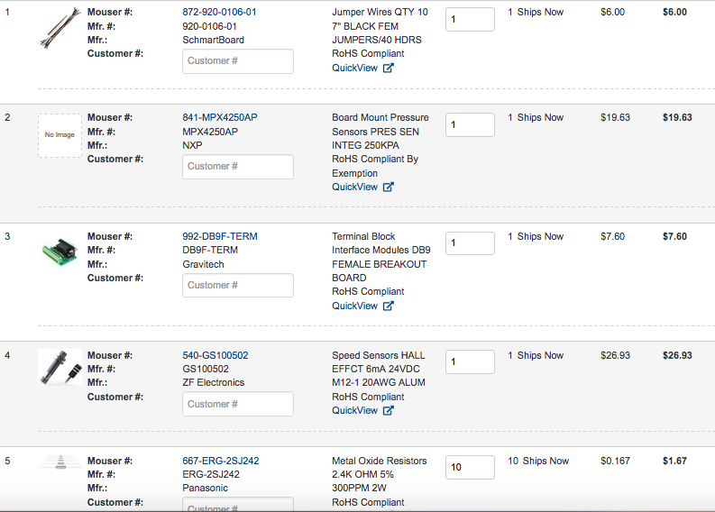
Thanks guys! I'll be adding more info here as I move along. I have a few areas where I have questions, I will post this shortly. I ordered these parts from Mouser:
Shipping was $8 for everything. I decided to get a basic DB9 (serial RS-232) connector temporarily, just for testing. I will look more into Bluetooth later. I also got another cam speed sensor, since the one I showed before is being used for my 951. I modified a stock reference sensor bracket to accept it, it will read the TTV 60-2 flywheel.
The other part worth mentioning from there is the jumper wire pack. These are 28 AWG, compared to the 36 AWG jumpers I already have. Those are fine for signals but some of the pins are used for power and ground, at times these pins can see several amps. The injectors are directly controlled by MS, via a saturated control signal. The IAC valve (late 944 only) also is relatively high current. The ignition coil is going to be up to 5-10 amps but this will be transistor controlled.
The next post will be pin assignments and other information for integration. After that, other topics for hardware setup are the TPS and fuel injectors (using stock requires ballast resistors).
 01-02-2019, 11:32 PM