When you click on links to various merchants on this site and make a purchase, this can result in this site earning a commission. Affiliate programs and affiliations include, but are not limited to, the eBay Partner Network.
Thanks for the write up Harvey. Not to take anything away from your write up but may I add the biggest departure of the 944 cooling system is the location of the thermostat. At the risk of being a cooling system nerd, the thermostat seems to maintain the water temperature coming into the engine. Water passing through the radiator drops the water temperature about 20 degrees and picks up 20 degrees by the time the water leaves the engine. This is why a 80c or 176 degree thermostat Will run these car's at about 89c or 194 degrees which is about right for emissions, fuel economy, and engine life. Most engines recirculate coolant around the engine while warming up and continue to do so somewhat after warm up. I believe Porsche wanted a 100% of the water to go through the radiator for the best possible cooling and this is what they came up with. From recent tests and measurements I did to try to figure this system out, the bypass port is closed off after the thermostat is about half way open. I found out the hard way recently that the thermostat seal inside the water pump housing is very important and often over looked.
BTW I'm proud to say I watch and attend NASCAR events. You won't see anyone "taking a knee" at a NASCAR event unlike those over privileged knuckle heads you'll see later today.
<Good write-up. What is a "944 R"?> C It's a mythical beast. Click the 944R link in the article and all will be revealed.
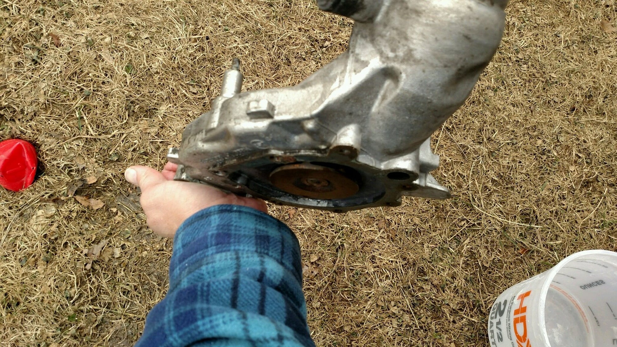
Mark, I'm very interested in your observations about the thermostat being able to close off the bypass flow. It is hard for me to tell exactly what is going on inside the water pump casting but I suspect you are right. Otherwise, why is there a rubber lined opening in the interior of the pump? It looks like the "small end" of the thermostat grows forward and closes off this opening, which somehow closes off the bypass flow. I ran water into the bypass opening and confirmed it makes it way to the impeller. I guess I didn't think to try this with boiling water!
The thermostat could technically modulate the water temperature around the setpoint range of 80C to 90C. Of course, if the heat load goes way up, the thermostat will just be wide open. As you probably know, if the water temp can technically go a little above the typical 100C value, due to the fact that the pressure cap can maintain an internal pressure about ambient. As conduction heat transfer rates are a function of the temperature difference (delta T) between the hot and cool side, the radiator should become more efficient and be able to transfer more heat as the water temp approaches boiling.
Anyway, all comments are appreciated. I can update the article as I get more good input like this. Thanks.
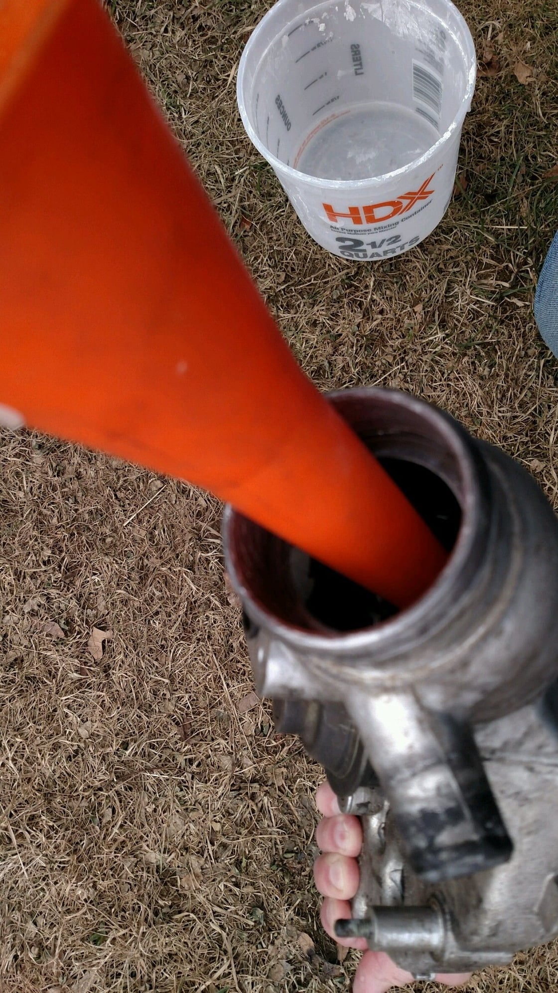
Harvey, I just recheck what ports on the water pump goes to what. With a funnel I poured water into the one inch hole in the thermostat end and it comes out the bypass port (triangle shape port) at the other end. I also covered the bypass port with my hand and filed the entire passageway with water. It doesn't go to the impeller. However the outer ports around the bypass port does go to the impeller. I'm 100% sure about this.
Last edited by marc abrams; 02-04-2018 at 02:38 PM.
Reason: spelling
here's a weird thing to ponder that occurred to me somewhat recently...
the gauge on the dash tells you the water temperature in the block near cyl 1/2, where it is still fairly cool since it just came out of the water pump about 5 inches ago.
the DME gets it's temp info from water being recirculated from the cylinder head "upper rad hose outlet" down to the water pump.
as marc mentioned, could be a 20 degree or more difference between what the gauge says and what the DME sees.
Spencer, I hadn't noticed this until you brought it up but you are correct. That said, the two fittings are very close together and both are inserted externally into the block. I would think that the block pretty much controls the show from a temperature profile, being such a massive heat sink. So I suspect that actual temperature difference between the 2 locations isn't that great. Conversely, the DME temperature element is bathed directly in the coolant, so it is a little strange that they didn't expose both to the same coolant flow. They could just has easily created the measurement point for both into the same coolant flow. Interesting.
I did omit discussion of these 2 temperature elements in my article. Once I can get a good picture, I think I'll add some discussion.
BTW, because of your question, I just noticed that the size of the tapped opening for the temp element that drives the gauge jumped in size somewhere between my 1984 block and my 1987 block.
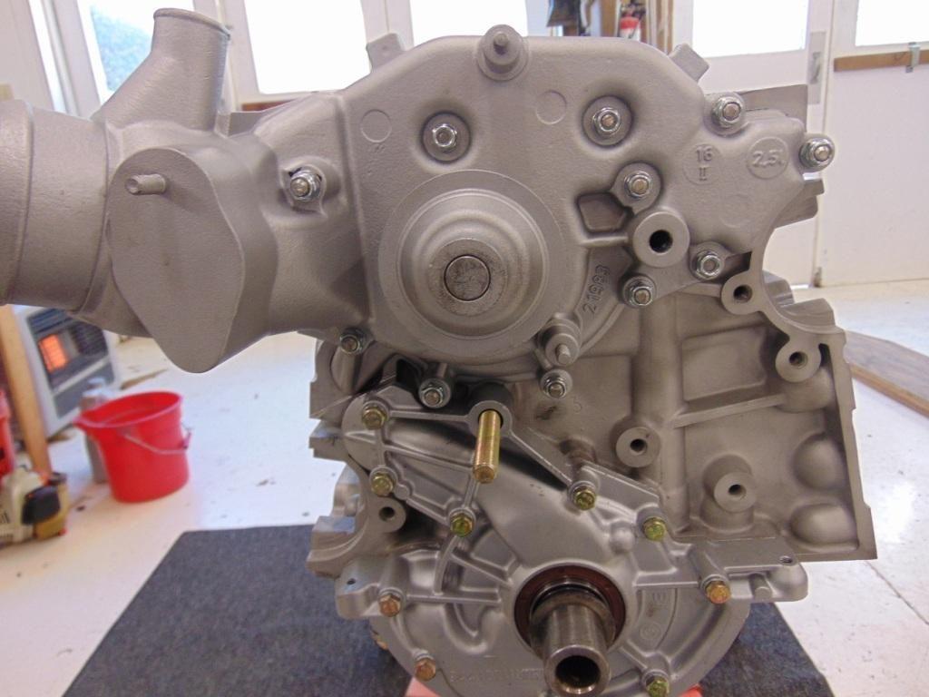
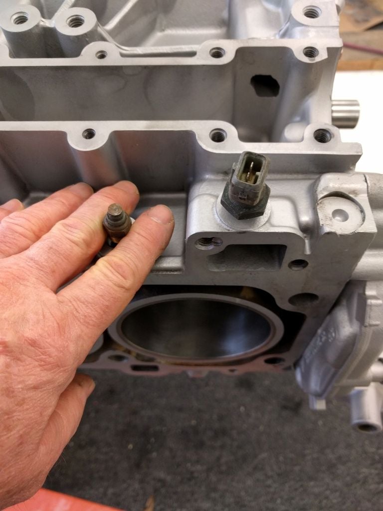
Here is a picture of the location under discussion.
Gauge element on the left, exposed to coolant next to the 1/2 cylinder. DME element on the right, exposed to bypass and/or coolant to the upper radiator hose.
yes the earlier model cars had an M10 sized sender that threaded into a blind hole in the block - did NOT actually contact coolant. single wire sensor.
somewhere in the 1985 model year they switched to an M14 thread touching water. this sensor has two wire posts but the early gauge still operates when the single-wire harness is connected to the right lead (my early 85 is this way).
late 85+ dash cars i believe used both contacts on the M14 sensor.
i'll be doing some cooling system experiments in the near-ish future and intend to relocate the sensors so they are both reading from the same spot to ensure what i see on the gauge is what the DME sees.
This is a bit of an aside question, but I notice the op's engine used in the article has had it's water pump mounting points heli-coiled. My question is regarding the holes at the top of the block. The 'bridge's of material there isn't very substantial. Is there a chance that even drilling out the threads there for a thread repair could weaken this area, making it more likely for a crack to form. I had to perform this repair on my own block, and am concerned that it will eventually fail. It's thin, and does have a cylinder head torqued down immediately above it.
i've done a lot of 944 WP's but never had one of those holes strip out though certainly it could happen.
though i'd probably be tempted to take it up to an M7 screw if it did.
re: that bypass port seems to me the water is flowing from "right to left", from the triangle hole to the 1" rubber-lined hole, then around behind the thermostat to the impeller (water does a 180 basically).
though i don't know if the port is entirely shut off by the moving t-stat - if so then the DME coolant temp sensor would be sitting in a stagnant bit of water since no water would be flowing past it anymore.
Tempest, I recently replaced my water pump and had to helicoil the top most left screw hole. Plenty of meat left after drilling the hole (.250") and I'm not in the least bit concerned about it.
re: that bypass port seems to me the water is flowing from "right to left", from the triangle hole to the 1" rubber-lined hole, then around behind the thermostat to the impeller (water does a 180 basically).
though i don't know if the port is entirely shut off by the moving t-stat - if so then the DME coolant temp sensor would be sitting in a stagnant bit of water since no water would be flowing past it anymore.
Spencer, from the measurements I took the bypass close off disk makes contact with the rubber seal when the thermostat is about half way open. As far as the coolant sensor I guess they felt it was close enough to a active coolant??
 02-04-2018, 10:32 AM