When you click on links to various merchants on this site and make a purchase, this can result in this site earning a commission. Affiliate programs and affiliations include, but are not limited to, the eBay Partner Network.
I made a model of 924 front suepension in Susprog and calculated optimal length of bump steer spacers and ball joint extensions.
Worked wonders in regards to handling.
Raceboy;14587986]I did similar to my race car few years ago.
I made a model of 924 front suepension in Susprog and calculated optimal length of bump steer spacers and ball joint extensions.
Worked wonders in regards to handling.
Wow, something you agree on really works, that's gotta be a first!
Does the only 50% of what I write in posts increase now !
OK R, you said "Thanks Harvey although i'd rather hear about solutions to something if you or anyone feels something needs fixing?" Here you go.
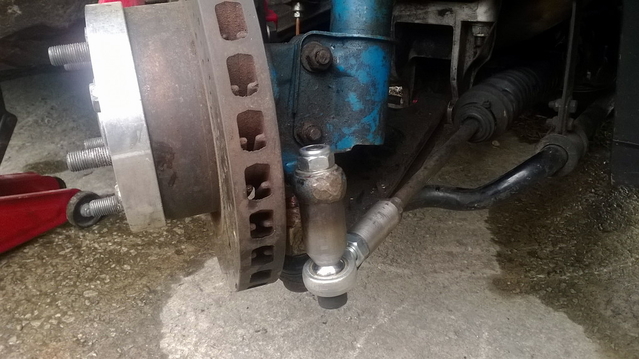
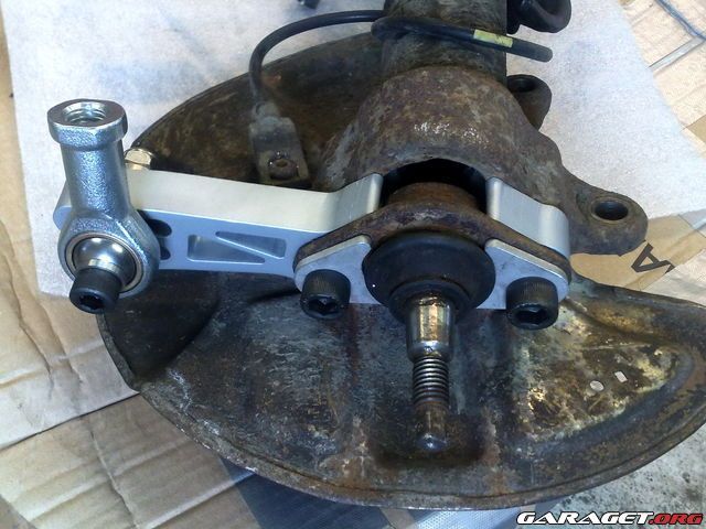
My concern is with the increased loads you have placed on the factory arm that the steering tie-rod end is attached to. As originally designed, this arm is placed primarily in bending, with a small amount of torsional loading due to the necessary offset of the arm's centerline versus the centerline of the steering tie rod end. With your design, you have dramatically increased the torsional stress load on this arm. At a minimum, you have introduced a lot of flex to the connection i.e. the steering inputs will have to overcome the flex of the connections. At worst, it will fail suddenly and you will loose steering on that side.
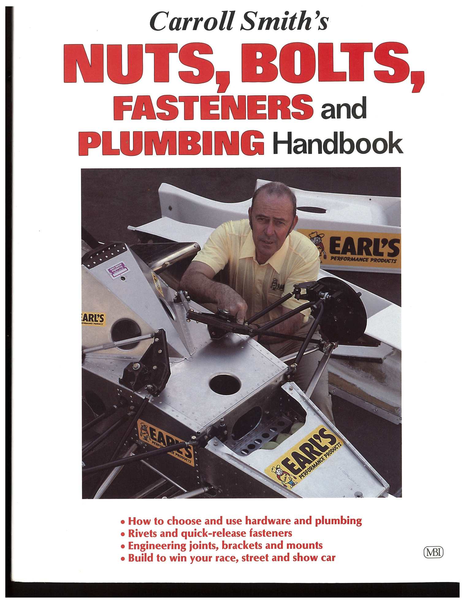
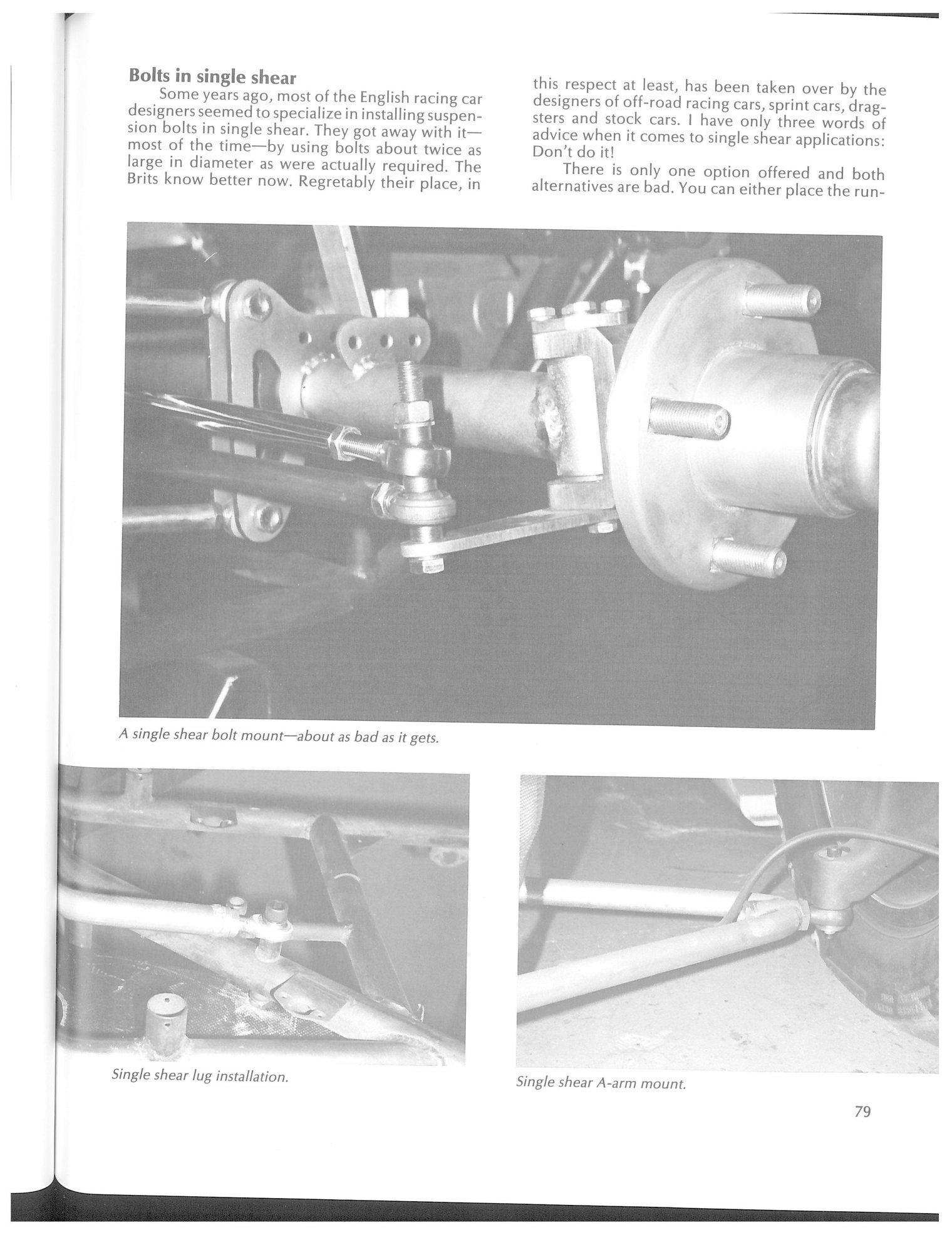
I have attached 3 pages scanned from a book by the well known race fabricator Carroll Smith.
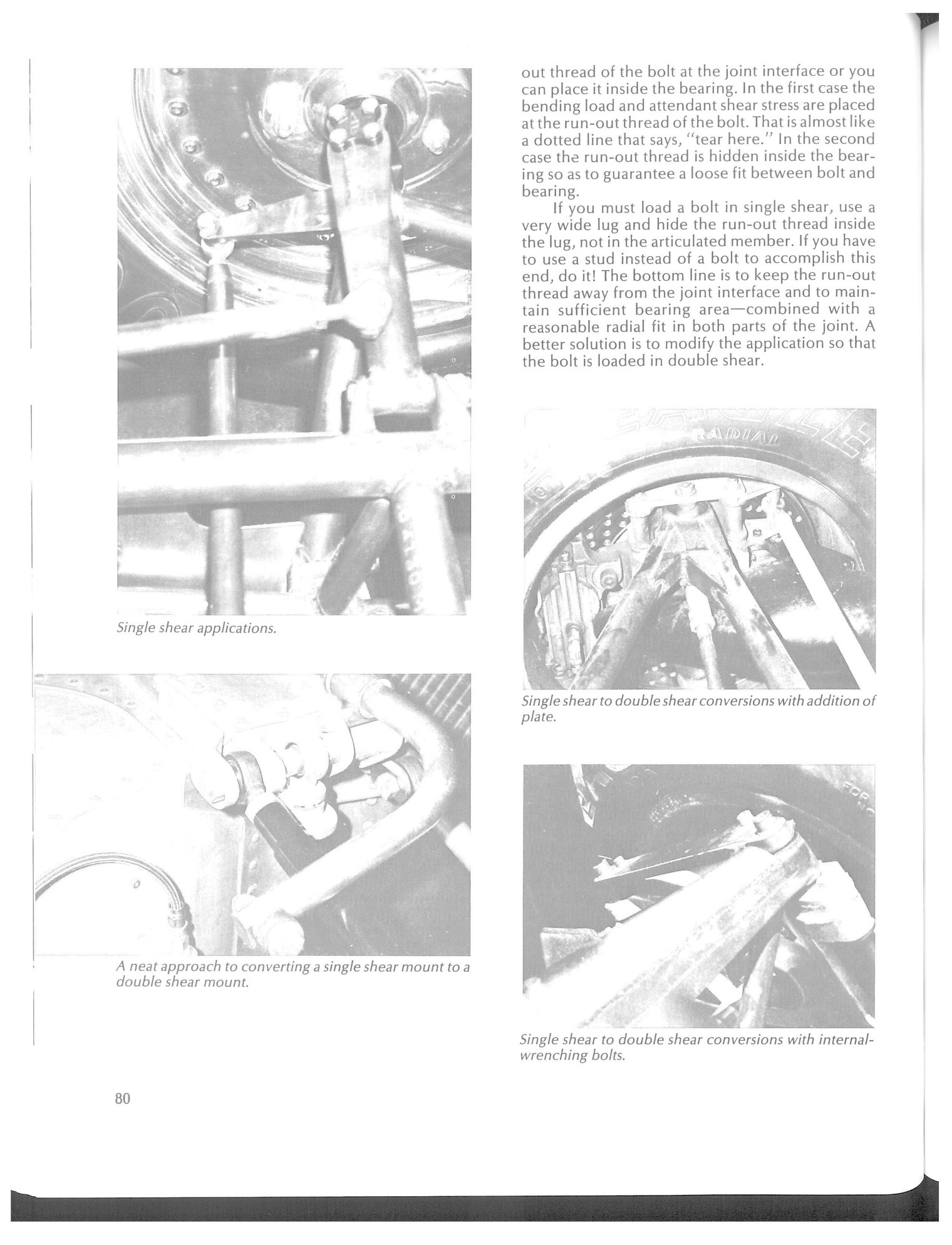
If you refer to the picture at the top of page 79 and the associated text, you will see his concern with these types of connections. You have made an improvement in that you have use a welded rod in place of a bolt but the issue remains of unknown stresses on the various parts. I would consider design validation by road testing and/or anecdotal info from an associate to be risky for this safety critical item.
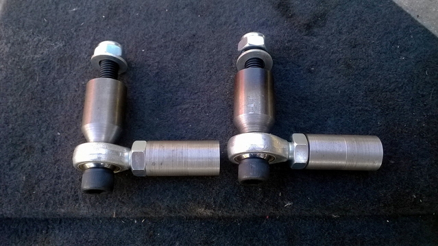
A fix would be to make the new rod a double shear connection. Several examples are shown in Mr. Smith's photos but in general you need an arm of similar strength and configuration to the existing steering arm placed below your spherical end connector from the steering tie rod. The gusset plate you have added has no strength in the direction of loads from the tie rod. A flat plate with significant section depth oriented in the direction to resist the tie rod loads, placed below the end connector, would be a vast improvement.
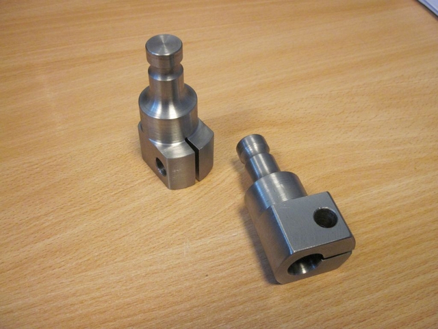
The rod you attached to the main spindle upright appears to be much beefier, although it still falls in the category of single shear. Not much to say there. I hope its strong enough. As noted by V2Rocket, and which I concur, the fabrication to modify the A-arm to provide a spherical bearing looks plenty stout.
Regarding the successful use of such configurations on a "race car", that only goes so far. They don't smash through potholes. They perform regular inspections. The driver is fully protected. Worst case off track excursions meet with Armco, not a damn tree!
I've said my piece. I suspect you will forge ahead. I just hate to see others try and emulate this setup without some heart felt peer review from me.
OK R, you said "Thanks Harvey although i'd rather hear about solutions to something if you or anyone feels something needs fixing?" Here you go.
My concern is with the increased loads you have placed on the factory arm that the steering tie-rod end is attached to. As originally designed, this arm is placed primarily in bending, with a small amount of torsional loading due to the necessary offset of the arm's centerline versus the centerline of the steering tie rod end. With your design, you have dramatically increased the torsional stress load on this arm. At a minimum, you have introduced a lot of flex to the connection i.e. the steering inputs will have to overcome the flex of the connections. At worst, it will fail suddenly and you will loose steering on that side.
I have attached 3 pages scanned from a book by the well known race fabricator Carroll Smith.
If you refer to the picture at the top of page 79 and the associated text, you will see his concern with these types of connections. You have made an improvement in that you have use a welded rod in place of a bolt but the issue remains of unknown stresses on the various parts. I would consider design validation by road testing and/or anecdotal info from an associate to be risky for this safety critical item.
A fix would be to make the new rod a double shear connection. Several examples are shown in Mr. Smith's photos but in general you need an arm of similar strength and configuration to the existing steering arm placed below your spherical end connector from the steering tie rod. The gusset plate you have added has no strength in the direction of loads from the tie rod. A flat plate with significant section depth oriented in the direction to resist the tie rod loads, placed below the end connector, would be a vast improvement.
The rod you attached to the main spindle upright appears to be much beefier, although it still falls in the category of single shear. Not much to say there. I hope its strong enough. As noted by V2Rocket, and which I concur, the fabrication to modify the A-arm to provide a spherical bearing looks plenty stout.
Regarding the successful use of such configurations on a "race car", that only goes so far. They don't smash through potholes. They perform regular inspections. The driver is fully protected. Worst case off track excursions meet with Armco, not a damn tree!
I've said my piece. I suspect you will forge ahead. I just hate to see others try and emulate this setup without some heart felt peer review from me.
Thanks Harvey, that's more like it Well done for replying.
So many adverse comments, constantly flow from a select few and nothing like any positive actions, explanations or suggestions arise.
I see what your saying, all these components have been on the car for a few weeks and a few hundred miles so far, many checks have been performed so far on their condition and I'm happy enough to continue with all of them in the immediate future, based on this design presented no issues on the racecar sample I was shown, all the work has been done by certified fabricators working in high standard industries (Aviation etc..) and the weights on all these components are substancially less than standard (Sprung & unsprung) and all the parts are high quality EG 12.9 Grade Bolts, threadlock & Lockwired heads etc...
Compared to some of the Racers solutions I've seen this solution is far more engineered and I also always run a good amount of Tyre profile 55 and not some huge Diameter things with 35-40 hence I have good give and compliance for irregular road surfaces and lastly a Shock absorber system which has special valves to cope with hard impacts (Developed for Circuit racers who like hitting the corner kerbs to gain laptime)
I did some diggin in my old photos when i was doing volvos.
Here is a kit that was wery succesful, in both drifting and tracktime.
We had non lowerarms failures, but the producer had some issues in the choosing of the material, i belive to remember it to be aluminium 7075 that was the solution.

 11-07-2017 | 03:42 PM