
weber balancing
 04-25-2008, 07:18 PM
#1
Racer
Thread Starter
Join Date: Nov 2006
Location: denmark
Posts: 258
Likes: 0
Received 0 Likes
on
0 Posts
i got inspired very recently.
i'd really love to learn how to balance the carbs myself.
i know well oiled pros like pete can do it by sound alone!, but what does the average non-pro idiot joe like me need in his arsenal to do it? (previously all i've done is lean out a rich cylinder that was sooting it's plug, with a quarter turn on the air screw with no metering)
what meters/sensors do i require? (hoping its not an expensive question)
 04-25-2008, 07:57 PM
#2
Rennlist Member
You are ambitious! First, I'm from the old school and prefer using a Unisyn - and you're in luck! They are still available from Performance Products here in SoCal (Automotion.com) under the part number 903558. Others prefer a Synchrometer, which I've never gotten used to using. That said, the rest of your tool arsenal will be small end wrenches and a couple of very good stubby flat-bladed screwdrivers. Add a Unisyn to your toolbox and I will teach you how to balance your carbs!
 04-27-2008, 09:17 PM
#4
Rennlist Member
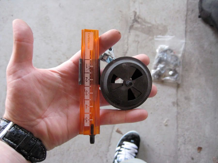
What the heck is that thing ??? Seriously...
OK, the next step is to provide a picture of either an actual carb (the outboard side) with numbers that define the different parts that can be seen, or a scanned exploded diagram of a 3-throat Weber - also with I.D numbers... I will key my text to your numbers (you're much better with computers than I am) and write a guide for you to use.
??? Seriously...OK, the next step is to provide a picture of either an actual carb (the outboard side) with numbers that define the different parts that can be seen, or a scanned exploded diagram of a 3-throat Weber - also with I.D numbers... I will key my text to your numbers (you're much better with computers than I am) and write a guide for you to use.
Last edited by Peter Zimmermann; 04-28-2008 at 08:00 PM.
05-01-2008, 01:39 AM
#6
Rennlist Member

Join Date: Oct 2004
Location: SF Bay Area, California
Posts: 239
Likes: 0
Received 7 Likes
on
7 Posts
Pete,
I found this image on the following Pelican thread.
http://forums.pelicanparts.com/showt...=weber+diagram
It's not the orientation you requested, but it is clearly labeled. I also need to tune my 40IDAs, so I'd very much appreciate your insights.


I found this image on the following Pelican thread.
http://forums.pelicanparts.com/showt...=weber+diagram
It's not the orientation you requested, but it is clearly labeled. I also need to tune my 40IDAs, so I'd very much appreciate your insights.
05-01-2008, 01:13 PM
#7
Rennlist Member
C4: That's a good start! Let's give red67 a little more time, and see what he might come up with. I'm working on the post in Word; when it's done all that I'll have to do is cut, paste, and add numbers...
Trending Topics
 05-09-2008, 12:02 PM
#9
Rennlist Member
Carb balance – please follow the instruction steps in order, there is a certain logic to it all, even though that logic might not be readily obvious!
1. The engine should have new spark plugs, either Bosch (WR5DC) copper core or a comparable NGK (BP7ES), gapped equally to .030”, and the point dwell must be within factory spec, as well as the ignition timing set properly. If your gas is as lousy as ours you might consider using spark plugs that are one heat range hotter (higher number for Bosch, lower number for NGK).
2. Remove air filters, but leave velocity stacks and filter bases installed. Each carb must be fitted with a throttle return spring.
3. Warm engine to about 140 F oil temp.
4. Use a small end wrench, 10mm, possibly 9mm, to disconnect carb drop links by popping the rods loose from the *****. Turn each spring-loaded screw (your #34) gently clockwise until it seats, then back each of them out five � turns.
5. Use your Unisyn to check the cyl #1-3 (left) carb (use lowest air draw position on tool). Now check the cyl #4-6 (right) carb with the tool at the same setting. Are they close side to side? If no, use the idle speed screw (on carb lever) to increase air draw on the low carb. Now are they close? If yes, go to the next instruction.
6. Do you have one cylinder that draws more air than the other 5 cyls? If yes, loosen the jamb nut on that cylinder’s air screw (your #39), aka cheater screw, and gently turn it clockwise until it seats. Is it still higher? If yes, that’s OK, but it should be a little lower than before the cheater screw was turned. Now, using the Unisyn, adjust those same “cheater” screws to equalize all six throats as close as possible.
7. OK, now hook up the drop rods and rev the engine a couple of times to clear its throat. Disconnect the rods and try to achieve a 1,000 rpm idle speed by using the idle speed screws (one on each carb lever) in conjunction with your Unisyn, keeping the air draw as close as possible side to side by measuring air draw on throats #1 and #4.
8. Starting with cyl #1 idle adjustment screw (your #34) turn that screw slowly clockwise (maybe an eighth of a turn at a time and then stopping for a moment) until you can hear the engine start to labor (listen at the tailpipe for a slowing of the idle speed).
9. When the engine labors, stop turning the screw, and turn it counter clockwise � turn, and immediately move to cyl #2, do the same thing, then on to #3, 4, 5 and 6.
10. Time to get that Unisyn out again and check air draw for all six cyls. Use the cheater screws to make any fine adjustments necessary to equalize air draw. Make sure that you snug down all cheater screw nuts in order to lock the screws.
11. Repeat instruction #8.
12. Clean both drop rods, be sure that the lock ring inside each ball cup moves freely, and apply a small dab of good quality grease (amber disc brake wheel bearing grease works very well) to each ball, on both the cross shaft and carb levers.
13. Connect one of two drop rods between the cross shaft and carb lever. There should be no preload, and the rod should rotate slightly once it’s clipped into position. If there is preload, or the rod won’t turn freely a small amount on its ball cups, adjust as necessary (this instruction can be done with the engine off).
14. Connect the opposite drop rod to the carb lever, and move its other end into position near the cross shaft. Adjust length of rod as necessary so that the rod connects to the ball with no preload. Like the first drop rod, this one must also be able to turn slightly on its upper and lower *****, almost as though it’s floating in place.
15. With the engine off have a helper push the gas pedal to its stop and hold it there. You should be able to push the carb drop rods a very small amount toward achieving full throttle – you do not want the linkage to fully open the carbs, rather, you want the gas pedal stop to act as your full throttle position, but still provide a safety margin to prevent damage to the butterfly valves. You never want the carbs to achieve full throttle before the gas pedal reaches its stop.
The above process must be done in order; any variation can easily skew your results. There is a possibility that you won’t be able to achieve “engine labor” on one or more cyls, post if you have a problem with this. If the engine seems rough, and moving an individual cyl’s idle mixture screw doesn’t seem to help, let me know. If you have light backfiring at steady speeds, especially in the 3600-4200 rpm range, let me know. If you don’t have full throttle, or if your gas pedal doesn’t snap back when released, let me know. The system can have any number of minor glitches; if that’s the case with your car we’ll work through them one at a time.
05-09-2008, 03:31 PM
#11
928 Barrister
Rennlist Member
Rennlist Member
I must say that the procedure as outlined by Pete was simple and well explained, even compared to the Weber manual. I say this as someone who has spent hours at the side of the road trying to make those &$*#& Webers run smoothly, and even succeeding once in awhile. No mention was made of jetting, so I concluded that the assumption is that the jets are correct as is, and not mention was made of injector adjustments. Good simple explanation.
I have copied it and put it in the glove box for reference.
I have copied it and put it in the glove box for reference.
05-09-2008, 07:46 PM
#12
Rennlist Member
Join Date: Oct 2004
Location: SF Bay Area, California
Posts: 239
Likes: 0
Received 7 Likes
on
7 Posts
Thanks for the very clear explanation. I have two cylinders that don't achieve "engine labor" when I tighten them (#1 and #5). I pulled the idle jets and shot compressed air through them (the jets, not the carbs), but that didn't make a difference. I found a Weber trouble shooting manual (for a different model carb), that suggested pulling the mixture screws and blowing compressed air through the idle circuit between the mixture screws and the jets. Do you recommend this? If so, is it better to shoot the air in the mixture hole or the idle jet hole, or does it not matter? Any other suggestions?
Even with the two cylinders not responding, the car is running much smoother now. I just turned those mixture screws to about the same number of turns as the others. At least I've gotten rid of the popping and spitting.
Also, I have a Gunson Gastester, so I can measure CO levels. Do you have a recommendation re: preferred levels?
Thank you so much for your help.
Doug
05-11-2008, 12:49 PM
#13
Rennlist Member
Join Date: Oct 2004
Location: SF Bay Area, California
Posts: 239
Likes: 0
Received 7 Likes
on
7 Posts
Found another Weber pic on Pelican at this thread http://forums.pelicanparts.com/showt...t=weber+adjust
Idle mixture screw is to the left and below the label in this pic (corresponds to #34 in the earlier diagram).
Idle air adjust screw is to the left of the label in the pic (corresponds to #39 in the earlier diagram).
Idle mixture screw is to the left and below the label in this pic (corresponds to #34 in the earlier diagram).
Idle air adjust screw is to the left of the label in the pic (corresponds to #39 in the earlier diagram).
 05-11-2008, 07:04 PM
#14
Rennlist Member
Ron: Correct regarding jets, but if anyone tuned into this thread isn't sure about their setup, I can post the correct jet sizes for most factory applications, and can come really close on a good starting point for most custom applications for 40 mm Webers (I need to know the cam specs, port sizes, valve sizes and compression ratio).
Doug: First, try to back out the idle mixture screws on your two "dead" cylinders a bit further. Go to six half turns, then seven, and see if that gets you anything. You just don't want to go so far that the spring loses its holding power. About air-cleaning, when you pulled your idle air jets did you separate the jet portion from its holder, hold the jet up to light and verify that it was clear? You have to do it that way, I've seen those jets impacted with crud so badly that I had to use a jet drill to clear them. Also, when you work on idle jets, make sure to wear clean latex gloves, and don't wipe off any parts with cloth or shop towels, a tiny piece of lint will play havoc in there. Regarding blowing compressed air into a carb orifice, I really don't like to do that unless the carb is disassembled on the bench. A little spritz of Chemtool B12 into the idle air jet passage and the idle mixture screw passage can sometimes help. Try this and let us know if you make a gain...
Doug: First, try to back out the idle mixture screws on your two "dead" cylinders a bit further. Go to six half turns, then seven, and see if that gets you anything. You just don't want to go so far that the spring loses its holding power. About air-cleaning, when you pulled your idle air jets did you separate the jet portion from its holder, hold the jet up to light and verify that it was clear? You have to do it that way, I've seen those jets impacted with crud so badly that I had to use a jet drill to clear them. Also, when you work on idle jets, make sure to wear clean latex gloves, and don't wipe off any parts with cloth or shop towels, a tiny piece of lint will play havoc in there. Regarding blowing compressed air into a carb orifice, I really don't like to do that unless the carb is disassembled on the bench. A little spritz of Chemtool B12 into the idle air jet passage and the idle mixture screw passage can sometimes help. Try this and let us know if you make a gain...
05-13-2008, 02:51 AM
#15
Rennlist Member
Join Date: Oct 2004
Location: SF Bay Area, California
Posts: 239
Likes: 0
Received 7 Likes
on
7 Posts
Success!
(I think).
The idle air jets were clear, but some of the o-rings on the idle jet holders and the mixture screws for cylinders 1 and 5 were a bit suspect. So I replaced them with new ones I had on hand and shot a bit of carb cleaner in the idle air jet passages and idle mixture passages. I started the mixture screws at 5 half turns and the cylinders responded when I turned them in. I did notice that some of the other four cylinders did not cause the engine to labor as markedly as others when turned in. While all now do cause a response, it just seems that some respond more gradually, while others respond more abruptly. Is that normal?
In any case, at idle all of the cylinders appear to be pulling the same volume (perhaps). I had to adjust the linkage a bit to keep the carbs balanced at both idle and 3,000 rpm. Number 6 cylinder is pulling less than any of the others at 3,000 rpm. Is it possible that it is pulling slightly less volume at idle and the difference is magnified at higher RPMs? Or could it be something else?