When you click on links to various merchants on this site and make a purchase, this can result in this site earning a commission. Affiliate programs and affiliations include, but are not limited to, the eBay Partner Network.
I did same. I went with sequential injection upgrade and sequential ignition for coil-per-plug setup.
I'm really struggling to find the GM TPS I need to work with the adapter I bought on ebay (linked earlier in the thread by OP). The seller of the ebay adapter told me to find an 85-88 GM TPS, but there are many different kinds, none of which seem to fit either the bolt pattern of the adapter or the throttle shaft.
As far as I am aware, the factory 944 Turbo TPS is a variable type and should work fine with a MS system. The early 944 and 944S use an on-off style TPS. You may need to figure out the resistance range for the 944 turbo TPS.
I'd like to bump this again while Michael's beautiful MS install is front and center. I know other guys here have gotten MS to work on their cars in the past in various capacities, but I think Michael and myself are the two most well documented installs here. I am in the process of transfering the MS from my blown up 951 into my NA. I hope that it will be far less of a mad scientist experiment the second time around and I will be taking cues from Michael in terms of harnesses and install since he did a much nicer job with his than I did the first time. I think between the two of us, we have successfully gotten the community interested in megasquirt and the possibilities of stand alone tuning in general. That being said, I would like to know where to expand from here. I would like to write a TunerStudio guide to help walk people through configuring the GUI, basic engine setup, and datalogging; as well as go more in depth into the nuances of setting up the trillion different aspects of getting the engine running correctly. What would you all like to see, what sort of questions are people having? I've been out of this for awhile with my car being down, and being really, really busy with work and school. I'm back a few months later and really cool things are starting happen, so I hope people continue to explore this as an option and help our cars come into the 21st century.
Doug has been educating me on MS since last year, and around January we started seriously discussing it for my car and for the 944 in general. I'll share a few things that my build incorporated, since the intent of this thread is to provide a guide to those who are considering MS. I'm making this post as an appendix to what is already here, to discuss some options that work well with our cars.
Custom harness
So you want to replace the DME/AFM/stock sensors/dizzy/etc....but why stop there? If your harness is ratty, it can be like building a house on a cracked foundation. This section will cover the basics. For more details, see the follow-up post.
Making a new harness is really not hard, in theory. In practice it's time consuming and a little frustrating for the first-time DIY guy (which was me). Don't let that deter you, it's very rewarding and you should be able to do it for under $100.
Before I get into that, when you should you not make your own? If your stock harness is actually in reasonably good shape and it's just a "for fun" car, think long and hard about this. Doug's approach makes a lot of sense, plus you re-use the DME relay. That's good, if you hate wiring and don't want to make/buy your own relay panel, but bad because that thing is a POS and inconvenient to get to on early cars.
If you hate wiring or are otherwise not comfortable with it, you may also consider just reusing the factory harness.
Ok, so back to planning the new harness (it's worth it). There are options:
you can buy a generic harness made for your MS, a few here. It will be a lot of work, but the wires are labeled already (like "coolant temp" for example) and are color coded. Recommended approach.
you can rebuild the factory harness, and then use Doug's approach. There's documentation online, here is a spreadsheet I made a few months ago showing places and pricing for using new connectors and wiring. (most expensive to do right).
you can get a Painless harness, or equivalent. Never done this, anyone have info?
I'll expand more on the first approach, since that's what I have info for. Get these materials:
harness (~$75)
soldering iron and 60/40 solder (DO NOT use lead-free, it will crack)
heatshrink assortment
terminal set, mostly ring and female spade
beer
Wire. You won't know much you need until you get there, but count on having to run 14 AWG back into the cabin to deliver switched 12v to a few parts. More on this later.
connectors for your sensors...get new everywhere possible. I really like GM connectors (cheap to buy new online) but crimping the pins is a bitch to get right until you practice.
speaking of crimping, get a good quality crimper. Avoid the "mash" type you always see at harbor freight, unless you like loose connections.
some sort of protection: sleeving, conduit, etc. Something to protect the wires in the engine bay. I used this stuff, it comes in different diameters.
Ok, so I made the outrageous claim that you can do this for under $100. You can! You just need to have a strong junkyard game. There are oftentimes new-ish cars in the premium section with perfectly fine connectors. It also helps if you already have basic stuff like a soldering iron, heat shrink, etc.
Realistically, budget around $200 for a quality build, it's the glue that holds together your hard work.
Let's talk about power and ground - this is outside the main harness, but you really will need one especially if you ditch the DME relay. You'll need a way to get 12v to a main relay, then a reliable and robust way to share it with everything. I recommend taking a few steps backs and searching youtube for "megasquirt wiring harness."
The bottom line is that there are dozens of ways to do this, you just need to use critical thinking and good judgement. If you open that playlist and find the video "Porsche 944 MicroSquirt wiring - part 2" you'll see my approach, which was modifying a kick panel to house all this stuff.
In short, you'll have a few things to manage.
the MS harness coming into the car, which terminates at the ECU
the relays - in addition to the main relay, you'll need a fuel pump relay and possibly a relay for your ignition setup. Note: you can still reuse the DME relay instead of having the main/FP relays, but why?
the fuse panel. You'll have to distribute 12v, do it right and get a $10 fuse panel from AutoZone. Make sure it's the type that has a big lug, which is shared on one side of all the fuses. That way, you can just plug in components via female spade connectors and they're good to go.
a junction board. Basically you want a way to interface MS with the relay/fuse setup, as well as with the in-car electronics. This includes the ground for the fuel pump relay, 12v supply to MS, the O2 sensor input, tach output, etc.
Before you do anything, make a wiring diagram, it will be trashy but who cares. You just need to force yourself to think about how it will all go together. Some questions will bubble up, for example "well where will I get switched 12v?" and "what gauge of wire should I get?"
It's easy to think about 12v and ground, but you really should be concentrating on current draw just as much. This will dictate a lot of things: what gauge wire, what size fuse, what can and cannot be run through switches (for example, ignition switch) and so forth. In general, be conservative. Almost everything has a current draw spec available, google it. Then plan on using wire that can safely handle the draw. Also, don't be stingy with your terminations, they pass the current too. If you need to, watch youtube videos on how to make a good solder splice and how to make a good crimped termination. In particular, look up how to make a Western Union Splice. It's a good soldering technique for making durable unions between two wires.
In general, your wiring should have this flow:
12v from ignition switch for main relay - see the follow up post for detailed info
Main relay activates. This allows current to pass from a 10 AWG wire (attached to battery) to a fuse panel. The wire between the relay and the fuse panel is also 10 AWG.
The fuse panel provides the following with 12v: wideband controlled (5A), the MS module (5A), injectors (5A per bank), fuel pump (20A), and whatever else you have.
In addition to the above, you want to power the activation side of the fuel pump relay from this fuse panel. That means that there are two connections coming off the fuse panel for the fuel pump: the fused power that actually goes to the fuel pump, and power to activate it. The ground for activating the relay is supplied by MS, which should interface with the relay in your junction board.
Also have at least one spare 12v wire coming out, you'll probably forget something. For example, my hall effect sensor needs 12v and so does the auxiliary air valve. Don't follow all these steps word for word, use your head and modify it if you know you have more stuff that needs power.
Label everything! I don't care if you use label printer or a goddamn pencil but YOU WILL THANK YOURSELF LATER.
There is more detailed info for wiring in the next post, it seems like a lot but it's really straightforward once you sit down with it. I just can't stress how important it is to do this as best you can, no shortcuts. You aren't sure about something? Overkill, tell yourself it's for reliability.
944 NA stuff
Doug did an awesome job of spelling out the MS install on his 951, but I want to expound on some options, and sometimes lack of options, that NA guys have.
Intake strategy. You won't be needing the AFM, but you will need a place to install your intake air temp (IAT) sensor. Think this through - you have a lot of freedom. Right now, my IAT is sitting next to the air filter because on an NA car the ambient temp is basically what the engine gets anyway. I think a really cool idea is to make a 'blank' tube that is the same length as the AFM. Then you weld on an adaptor plate that bolts to the factory airbox, effectively deleting the AFM. Then it's a matter of drilling and tapping the tube to accept your IAT (usually 3/8" NPT).
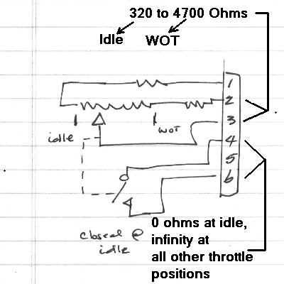
Throttle body. I found it easiest to use a NA throttle body with a 951 TPS, but YMMV. You cannot use the stock TPS. The 951 part will install onto the NA throttle body, but you may need spacer washers between the two in order to avoid bending the base of it. Just use common sense. For the connector, it's a Bosch 6-pin, you can find them new online for ~$20 or you can scavenge from VWs and Audis at the junkyard. Regardless, you will only use the first 3 pins of the connector (referring to pins 1/2/3 as labelled on the TPS). Pin #1 gets 5V from the MS TPS power wire. Pin #2 is grounded, use your signal ground wire. Pin #3 gets connected to the MS TPS SIG wire. The other 3 pins are not used, so it doesn't matter if the 951 TPS has a faulty idle or WOT switch.
Diagram, credit to Bruce Arnn:
Wideband O2. Doug pointed this out, but just get one...it is a great tool in the toolbox. Plus, cool gauge in the cabin!
Idle air control. You can probably delete it if you live in a moderately warm climate, you can tune your car to run ok without one. For an early car, all it needs it switched 12v since it's basically a resistive heater pointed at a bimetallic spring. On a late car it's a 3-pin valve that gets a PWM signal from the DME. MS has the capability to operate this valve, you're on your own for that unless someone else comes along with the info. In the meantime, consider downgrading to an early 944 idle valve, which require no configuration and is fine for this motor.
Injector choice. Don't go below 25#, and there's no reason to go above 35#...it's like wearing your dad's shoes when you were 5 years old. Make sure they are high-z injectors, and will physically match the stock ones. I used Saab 2.3 turbo injectors, which are Bosch p/n 0 280 150 431 and they are great. $100 with a 5 year warranty, they are 30# and 12 ohms impedance.
Calibrating the coolant temp sender. The stock part will work, the tricky bit is calibrating it. Assuming the sender is in spec, and you are using TunerStudio, go to "Calibrate Thermistors" and select "BMW E30 325i" under "select a common sensor" drop-down menu. This calibration is for a Bosch 0 280 130 026 coolant temp sensor.
According to some 'parts cross reference' lists, this is the same part as a 944 stock coolant temp sensor. If you have any doubts, just buy a brand new part. If you search "0 280 130 026" you should find plenty of online retailers. The 944 head is tapped for the thread on it, so it is plug and play. The aforementioned BMW E30 built-in calibration is designed for this part - you should still verify that you are getting reasonable readings in TunerStudio. If not, make sure the sensor is cleanly grounded via the signal ground.
I'm not going to go into tuning an NA 944, mainly because that's the stage I'm in at the time of this post. There will definitely be info posted later, and to be frank, Doug is the better person to be getting into this by a mile.
Other options
So you've read all these pages, and it seems like there are a lot of things to do and just as many things you shouldn't do. With respect to hardware, there are actually tons of options...that's one of the best parts about MS.
Ignition. You can use LSx coils like Doug and I have, or something else. I think EDIS-4 is a good match for our cars, maybe I'll do that next time just for the challenge. You can use the stock distributor with a little work, if you really wanted to.
Triggering. The stock flywheel generally won't work, as the tooth count is not supported by MS. I said 'generally' because there are workarounds. But why? The signal is noisy, plus the sensors are susceptible to being pieces of crap. Speaking of noise: Many modern engines use hall effect sensors now, and you can get them to read a ferrous trigger wheel just like a VR sensor without worrying about EMI. It's what I'm running on mine and it's clean. The power wire goes to 12v, the ground wire goes to the signal ground, and the output signal goes to VRIN+. You leave VRIN- floating, and no need to ground the sheathing.
Connectors. You can use anything from OEM Bosch all the way to junkyard scraps. I recommend opening the hood on a few different cars and just laying hands on them. Maybe you like the GM weatherpack sensors, or the Honda style. Another contender is the Mitsubishi 3-pin, which is really neat and provides excellent protection. The wires wicked up solder easily and it just feels very solid overall. The design is different from most, but in a well-engineered way.
Wanted to follow up the other post with more wiring and NA 944 specific information, now that the car is running and driving well on MS.
Maintaining gauge functionality
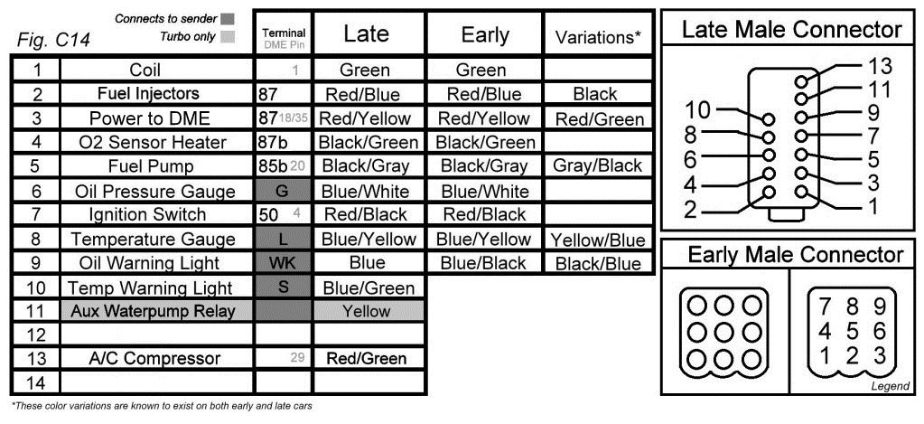
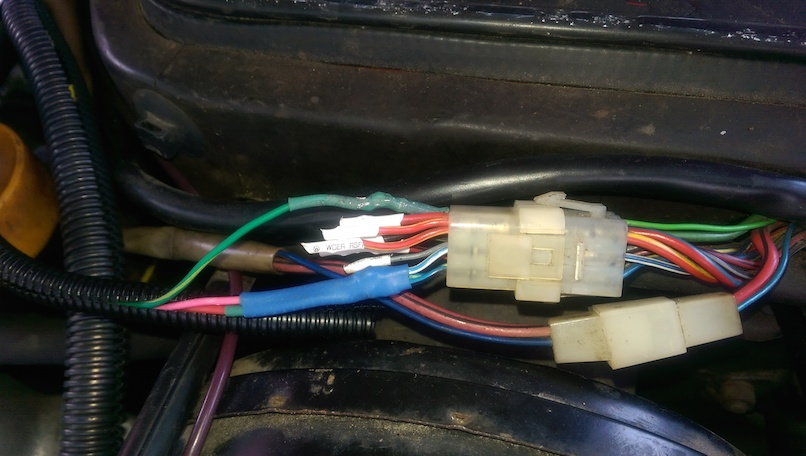
Your stock harness has runs for the oil pressure sender, the water temp sender (for the gauge you see on the dash) and the tachometer. If you replace the harness with your own custom job, you should retain that functionality. In brief, there's a plug near your brake booster that connects the DME/engine harness with the rest of the car (i.e. fuse panel, cluster). Edit: the late 944 has this connector in a slightly different location, you'll need to find it. Credit for this figure goes to edredas on 924board. Keep this diagram handy! This post will refer to it a lot.
The tachometer
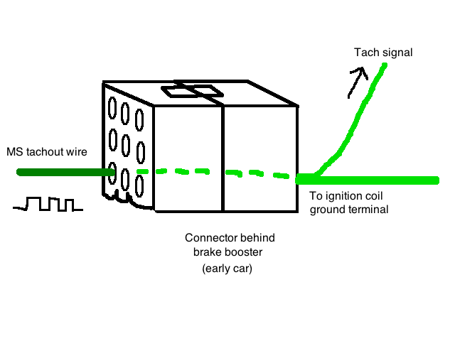
If you look at the DME pin diagrams online, you will see that one of the pins is labeled "tachometer." It's not really though - this is for the economy gauge and the shift light. The actual tach signal comes from the positive terminal of the coil (thick green wire, pin #1 on the above connector diagram). There is a smaller green wire that branches off this wire which goes to the tach. On an early car, this 'branch' occurs in the female side of the connector, you can plainly see two green wires coming out where one went in. On late cars it's probably the same place but you may have to look in the passenger footwell.
If you kept the ignition coil (and the stock harness that runs to it) you're ok, but if you moved to a different ignition setup this part is important. MS has a "tachout" wire, you just need to connect this to the green wire. I found it easy (and non-permanent) to just get a spare connector, like cut out of a junkyard car or a spare/bad harness you know will never be needed. Now just connect your MS tach wire to the thick green wire on the male side of the connector. Now you can plug that into the female side which is still installed in your car, and the MS tach wire will go to the tach's green wire.
Note that the thick green wire will also be getting the tach signal. Since the coil is no longer there, the harness will be floating. I recommend you isolate the green wire's termination with heatshrink and make sure it is not flapping around the engine bay. The black wire was the coil's +12v supply, which will still be getting +12v but more on that later.
Ok - so one way or another, you connected the MS tachout wire to the green tach signal wire. However, there is also a power connection to the tach that needs to be remade. Note: if you kept the DME harness and the DME relay installed, you already have this and you can skip this part. But if you yanked the harness in favor of the new one, you'll need to follow this to have a working tach.
On the early 944, there's a 2-pin connector under the steering column. One wire is black, and one is yellow and black. This connected to the DME harness, right after it connects to the DME itself. The black wire needs to get +12v from your powered fuse panel. Make sure it is switched +12v. On my car, I just ran a wire from my fuse panel behind the center console and used a spade connector to clip onto the male pin. On a late car, you're on your own, I recommend studying the wiring diagram. It will probably be a black wire as well.
A note about the yellow and black wire: remember how I said that the "tachometer" pin on the DME actually isn't a tach signal? It goes to this wire, which is for the economy gauge and shift light. It seems to be a fuel injector load/duty cycle signal. Although I'm sure MS could send this output, I have no idea how that signal behaves or how to broadcast it in TunerStudio so I left it disconnected. Hence, the mileage gauge is the one gauge that won't function.
Oil pressure and water temperature
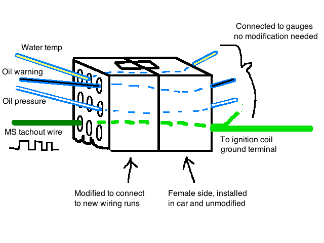
If you kept the stock harness, you're already set. For those with custom harnesses, keep reading. It turns out that even though the DME doesn't use the readings from the oil pressure and water temp senders, the wiring for them is still run through the DME harness. But instead of going to the DME, these signals go to the connector at the brake booster, so removing the stock harness means remaking these connections.
Rigging up the stock sending units is not a big deal, you're just getting a length of wire and literally completing the circuit. On an early car, the senders use spade terminals. On a late car, the water temp sender is different so be prepared to pave your own way. A tip is to look at the color of the wiring. At the connector (by the brake booster) you will see certain wire colors (e.g. blue with a white stripe). Now look at the diagram above and you can see that's for one of the oil pressure sender terminals. You double check your work by looking at the factory harness, and you see that the 'blue with white stripe' wire goes to the oil pressure sender. Just use your head and your instruments will be fully functional.
In the tachometer section, I recommended getting a spare connector so that you can use the male side as a sort of adapter. Again, highly recommend this, your life will be easier here too. Now you just take the wires (that you just ran to the senders) and join them to the right pins on the connector. Note that this graphic is mirrored because I wasn't paying attention so double check all your work against the connector diagram.
What about the other wires?
If you look at the connector diagram, you'll see that the there are several wires that now go to nowhere (floating) such as "power to DME" and "fuel injectors." These are power (or ground, in the case of the fuel pump) connections that primarily went to the DME relay or some other relay panel component. If you want to keep your DME relay, you will use these connections.
If you're anything like me, migrating to MS is made even better when you can move away from 'trouble' parts, like the DME relay. I recommend removing the DME relay and leaving all of those non-sensor pins disconnected, you can easily make a standalone relay/fuse panel to recover the functionality. I'll go into more depth in the next several sections.
Here's what mine looked like before I finished installing sheathing over all the wires:
Powering the main relay
In the stock setup, the ignition switch would power the DME relay's first stage, which in turn powered the DME and the injectors. So to power your own standalone main relay, you just need to use the +12v wire that comes from the ignition switch. Earlier I said:
Since the coil is no longer there, the harness [to the coil] will be floating. I recommend you isolate the green wire's termination with heatshrink and make sure it is not flapping around the engine bay. The black wire was the coil's +12v supply, which will still be getting +12v but more on that later.
You can use that black wire as the +12v for activating the main relay, since it goes through the ignition switch. So basically, when you turn the key to 'accessory' or 'run' or 'crank' the main relay is activated. You may be able to use the "ignition switch" pin on the brake booster connector but I haven't verified that it will work. If I do another MS 944, I'll try and use it, since it will be a cleaner install.
Now that the main relay is powered, refer to my previous post in this thread where the 'power flow' is discussed. In short, you'll want to power a fuse panel, which will then distribute 12v to devices that require it (injectors, fuel pump and its relay, MS module, wideband controller, ignition setup, etc).
Powering the fuel pump and its relay
There are two ways to do this, one involves reusing the DME relay. This makes sense if you're already reusing it as your main relay, but you really need to have a solid understanding of how multistage relays work and you will pretty much be on your own. However, I strongly urge you to take this as a chance to migrate to a standalone relay panel. If you choose to do this, you'll simply use a standard 30A relay for this. I'll assume it's 4 pins for this. You can use a 5 pin, but make sure you know which pins are which.
Wiring: you will give one of the relay activation pins +12v from the main relay. This is easy if you make your own fuse panel. You will also give the power side +12v, through a 20A fuse. This leaves two pins left: the ground for the activation side, and a pin that will deliver +12v at up to 20A.
For the ground side, connect that to the MS fuel pump wire. This wire goes to ground when MS detects that the engine is spinning. The DME had this same functionality, and it's a safety thing, so don't just ground it. MS will also ground this wire for about 2 seconds once the key is turned on, as a priming pulse to help the car start faster. This is a nice touch that the DME doesn't have.
Now the last pin - the +12v delivery. This will integrate into your car's harness. There is a loom of wire that runs through the driver side door sill, you can access it by pulling up the black plastic strip and moving back the carpet. There will be a fat black wire with a green stripe. That goes from the stock fuel pump fuse all the way to the fuel pump. The fuel pump is grounded at the back of the car, so all you need to do is connect your relay's +12v pin to this black/green wire.
My solution was to remove the stock fuse for the fuel pump, and then tee in a wire to the black/green wire. I ran this new wire to the +12v delivery pin on the fuel pump relay and it works as intended.
Doug/Mike,
Did either of you retain functioning AC? I see on pin 29 of the 951 DME is (AC Compressor +) and it goes to pin 7 on the engine bay harness. No idea how to wire that up with my DIYPNP and no idea where it would need to go. Curious for your observations.
Doug/Mike,
Did either of you retain functioning AC? I see on pin 29 of the 951 DME is (AC Compressor +) and it goes to pin 7 on the engine bay harness. No idea how to wire that up with my DIYPNP and no idea where it would need to go. Curious for your observations.
No AC on my car. Under what conditions would the DME activate the relay?
Doug/Mike,
Did either of you retain functioning AC? I see on pin 29 of the 951 DME is (AC Compressor +) and it goes to pin 7 on the engine bay harness. No idea how to wire that up with my DIYPNP and no idea where it would need to go. Curious for your observations.
No A/C in my car, but that was the case long before I went down the MS path. I wasnt aware the DME had anything to do with it, as far as I know it is a "dumb" circuit that simply uses a switch in the cabin (and a pressure switch on the compressor) to power a relay with provides +12vdc to the compressor. That being said, it'd be a simple thing to have MS control the A/C (it can even raise the idle to compensate for the load on the motor) via one of the unused outputs. You could use any type of switch/relay combo you wanted, or even reuse the factory dash switch and relay. You actually dont even need MS to control it, all you need is the switch >>> relay >>> compressor if I'm not mistaken.
Was going through my documents and found this spreadsheet I had made earlier, wanted to share for anyone going down the standalone path. It has almost all the parts you'll need along with the prices and where to get them.
There are couple tabs at the bottom (sheets within the spreadsheet) for different cases... a conservative case where one buys almost everything new, a 'thrifty' case where one visits junkyards, and I left in my case as an example of how you can mix and match. You can save even more money by already having a wideband or timing light among other components.
I've been doing a lot of research on sequential and semi-sequential fuel the past week or so, and wanted to share my 944-specific findings for anyone looking at this conversion. I'm pretty bored at work right now so I want to discuss the Motronic batch fire vs. sequential.
So here is the skinny: your car came with batch-fire injection. What that means is the fuel delivery is untimed, the DME simply injects a known amount of fuel into the intake ports every cycle (2 crank revolutions) and when the valve gets its turn to open, the fuel gets sucked in. It's very simple and works fine, even though it is relatively primitive. The DME fires cylinders 1 & 2 together, and 3 & 4 together. If you want to run sequential or semi-sequential, this pairing needs to be changed, more on that later.
The main issue with batch fire (aka untimed injection) is low RPM response and idle quality. It turns out that the intake pulses from adjacent cylinders reverberate through the intake runners in such a way that some of the "waiting" fuel gets splashed out into adjacent cylinders. It's not a 944 problem, it's normal, and is called intake pulse reversion. The effect is that you need to add more fuel at low RPMs - that's needed for the cylinders on the intake stroke to get the required amount of fuel. Otherwise you have a lean condition. In short, you have to run the engine richer at idle and low RPMs to achieve good running. Batch fire engines idle best in the ~13s for AFR. That's not really a huge deal, but low RPM response takes a small hit. At higher RPMs it doesn't matter as much because the injector pulses are much higher. With respect to peak power, batch fire does not negatively affect this believe it or not.
So then, the main attraction of moving away from batch fire is a smoother idle and a little more responsiveness at low RPMs. With MS it's all settings at this point, nothing too tricky. However like I said in the bold font above, the stock pairing is not compatible from here on out. This is because unlike batch fire, sequential is timed injection: the fuel delivery is timed to the intake valve opening. For a 4 cylinder sequentially injected car, it will take 1 complete cycle (2 crank revolutions) to fire all 4 injectors once... it's a sequence and that's why it's named as such. So you can see the problem with having 1 & 2 paired, and likewise with 3 & 4. You will need to separate them so nothing is paired, this requires a MegaSquirt with 4 injector drivers. Obviously timed 1-3-2-4.
That's cool but there is another option I mentioned earlier - semi-sequential injection. It's sort of a mashup between batch fire and sequential. Like batch fire, it fires cylinders in pairs. But like sequential, this firing is timed with respect to the intake valve opening. The pairing (called a channel) squirts once every crank revolution, so that one of the cylinders in pairing gets a squirt on time. The not-on-time squirt remains in the port. During the next crank revolution, this happens to the other cylinder in the pairing. This is true for all pairings. Because of that, you can again see how the stock pairing will not work - each pair must consist of cylinders that are 360 degrees apart in terms of crank revolution during a cycle. In our cars, that 1 & 4 and 2 & 3.
The other reason semi-sequential makes sense is because you only need one speed/reference sensor (assuming a missing tooth or equivalent timing setup). With normal sequential, you also need a cam sensor to tell MS which part of the cycle the engine is in. With semi, it doesn't matter because the same thing is happening every 360 degrees of crank rotation so all it needs it crank speed and position.
Having driven my car with batch fire and semi sequential via megasquirt, I did notice semi was smoother and revved more cleanly. My idle AFRs were very very steady, before they would fluctuate rapidly around a narrow range of values (no actual idle hunting though).
So now you know about the options, let's dig into tuning. I'll cover this in a future post, maybe later tonight if I remember. Hope this info helps people, it took me a while to wrap my head around it. Just want to make the info more readily available for future research.
I have no life so here's part II of setting up sequential/semi-sequential, for a 944.
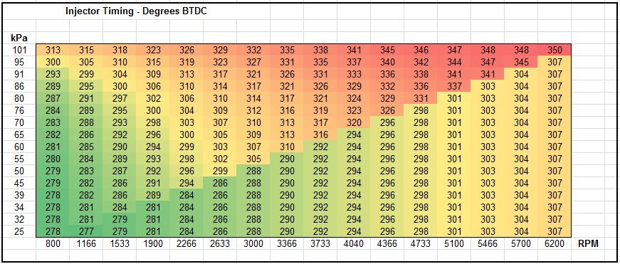
Just like the spark advance table and the VE table, there is also a table for the injector timing if you choose to move away from batch fire. If you don't want to bother, batch fire is honestly not that bad. But you've come this far with tuning and this is way easier than tuning spark or fuel. The table is in degrees BTDC (before TDC).
There are a couple things to consider with timing the fuel: 1) when does the valve open? 2) at what point in the valve opening process should the fuel be delivered? and 3) how far in advance does the injector need to fire to compensate for the injector's opening time, and the time it takes for the fuel to get from the injector to the valve?
I know that last point sounds petty but at high RPM it can be as much as 50 cranks degrees. But let's start with the first point: the cam. This is readily measurable; here is a page where a 'lister uploaded some cam specs for our cars: http://members.rennlist.com/951_racerx/CamProfiles.pdf
You can see that the intake valve opens 1 degree ATDC (that stands for after TDC) for the NA and for the 951 cams. So keep that in mind.
The second point is a matter of when you want the fuel delivered. Hint: it's NOT when the valve is fully open. it's not when the valve is open at all. You want the fuel to hit the valve when it's fully closed and about to open. The valve is hot and will evaporate the fuel, allowing a better mixture. I didn't know about this until I started researching about tuning fuel timing, but now it makes sense why the engine runs smoother at low RPMs with timed injection.
The last point is hard: you need to get a sense for the intake runner geometry. Most people let the car break into a (fully warmed up) idle and adjust the "base timing." In reality that just means the amount of degrees BTDC (on the crank) that the car idles best at. You quantify that by looking at your wideband. At the 'correct' timing, the idle AFR will be the most rich, relative to the others. But it will still run and idle even if you are off by 180 degrees, but just not as well (remember, batch fire isn't even timed and still runs the car ok). So at this point you're optimizing more than anything. On my NA, this "base timing" is 270 degrees BTDC, approximately.
Now you need to flesh out the rest of the table to account for the other factors I listed in the 3rd point, like injector dead time and mixture delivery. I made a spread sheet that numerically integrates the cam profile and uses basic laws of motion to approximate these effects, if anyone wants a copy drop me a line and I'm happy to share it. It gets you in the ballpark. It loads your VE table and accounts for flow dynamics based on your engine's configuration, but ignores compressibility effects in the runners. Here's what I calculated for my car and it seems to run well:
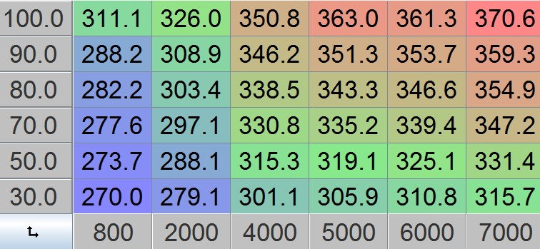
You can see how the RPM and VE affects the timing. and here's how it's actually implemented in TunerStudio:
Note that when you tune this table, it's an "end of pulse" table. That is, you're telling MS that this is crank angle (BTDC) it should aim to complete the pulse/squirt by. So if that pulse takes 6 ms, it knows to start the pulse 6 ms before the target angle arrives. The spreadsheet I made also calculates "start of pulse" timing, which you can select in your tune.
At the end of the day, you can't really quantify this with math... it's something you mess with until it's as smooth as you can make it. It's worth doing and makes the 944 an even better car than it already is.
 06-01-2015, 02:08 PM