
My 1967 912 Build Thread
 02-07-2015, 05:22 PM
#376
Professor of Pending Projects
Rennlist Member
Rennlist Member
Thread Starter
And we are moving people... we are moving... Ron, please jump in if I misinterpret what I am supposed to be doing here....
(1) Placed the Top End Tool to measure that the cylinder tops are in plane... This is with just the cylinders on the case. No pistons, no base gaskets.
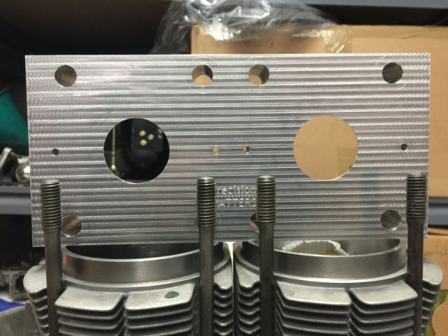
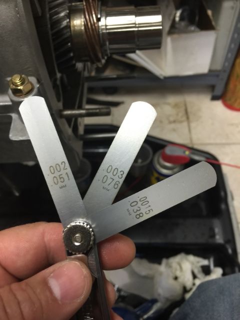
That side of the tool that is on top of the cylinders has a .004 feet resting on the outer most cylinder tops. So I measure the inner top to confirm clearance... with the newly acquired gauge blade set...
I have the same gaps... I tried all the way to .004"... so far, all good.
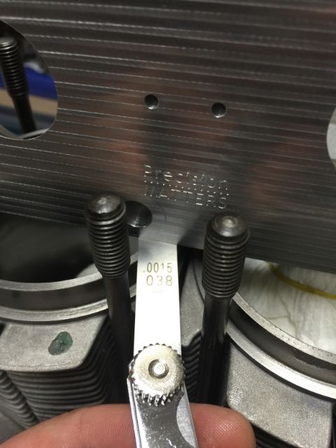
(2) Turned the tool around. That side is completely flat... try to measure for any indication that the tops are not offset... nope... could not get a blade in there (.0015 is the thinnest gauge blade I have)..
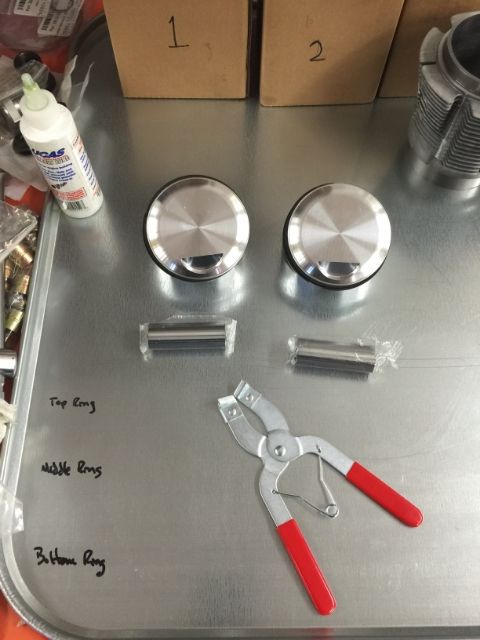
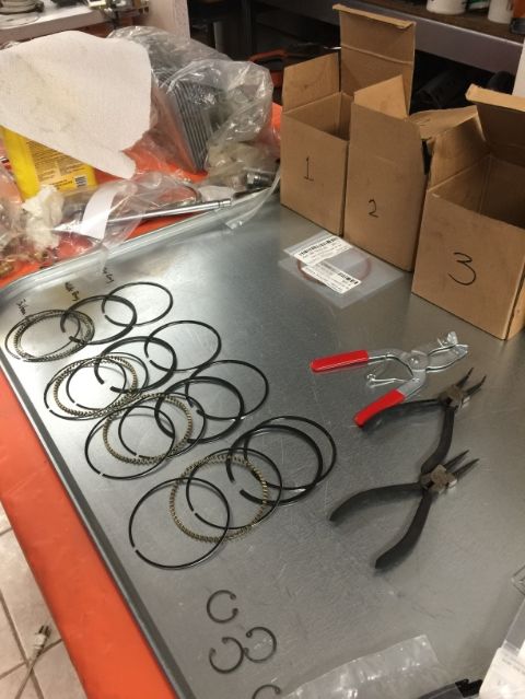
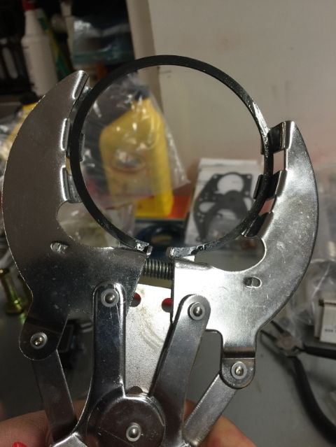
(3) To measure deck heights... first I need to remove the piston rings... I could not find the tool I wanted so had to settle for the one in the photo... ordered the other one from Amazon...

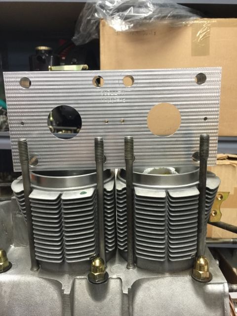
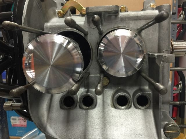
Base gaskets installed... I used the 1 mm gaskets
Install piston, without rings, to connecting rod... I did not bother to insert the circlips just in case...
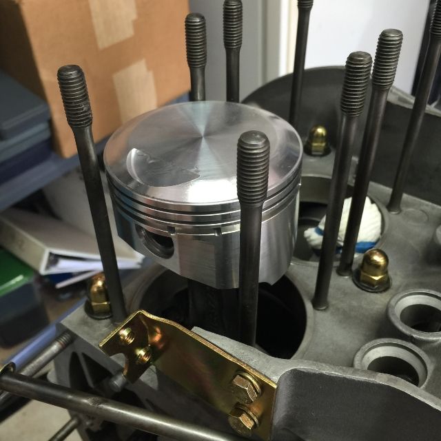
Install cylinder...
Rinse and repeat for the other side...
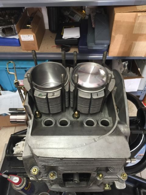
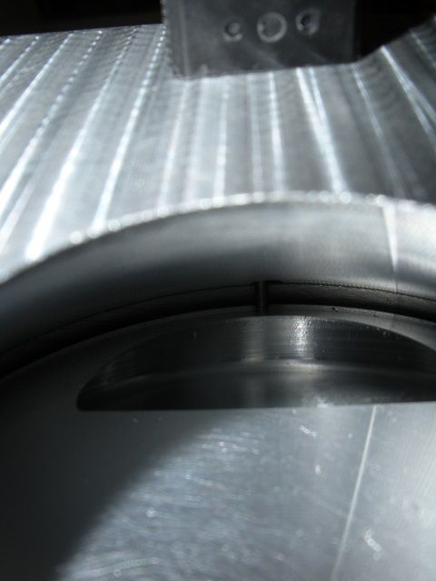
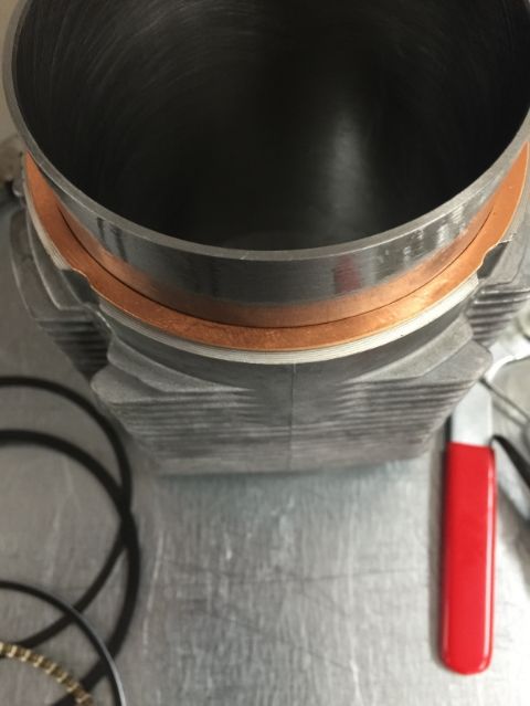
And I wanted to have a photo where the gasket can be seen... going back to a question made earlier in the thread... you can see it and you can measure it in place...
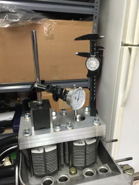
Install the tool and torque down each nut to 20 ft-lbs...
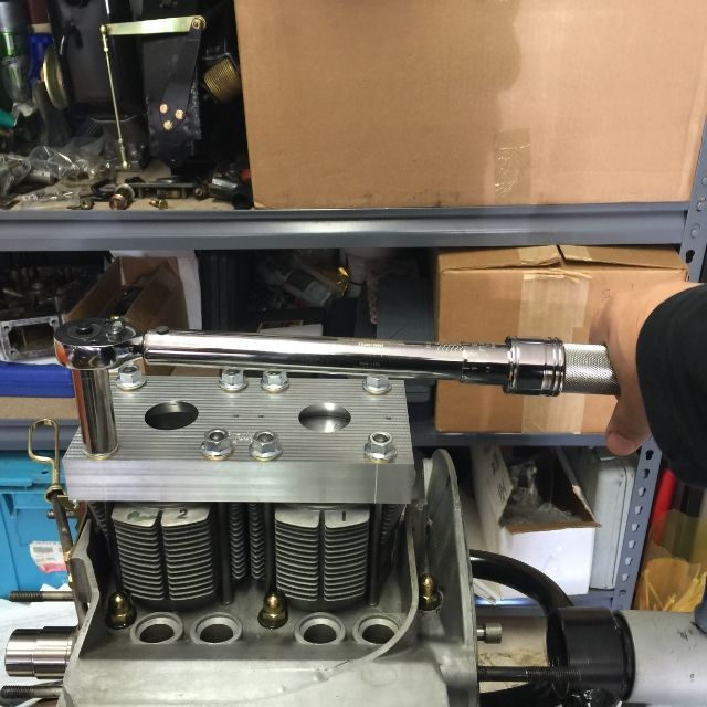
I use the dial indicator to make it easier to be certain that I am at TDC... well, the truth is that I wanted to use the dial indicator, hhehehehe
I need to do this for all four pistons/cylinders... I will measure #1 again a couple of times, move to #2 and then setup to measure 3 & 4.
Back in a few...
(1) Placed the Top End Tool to measure that the cylinder tops are in plane... This is with just the cylinders on the case. No pistons, no base gaskets.
That side of the tool that is on top of the cylinders has a .004 feet resting on the outer most cylinder tops. So I measure the inner top to confirm clearance... with the newly acquired gauge blade set...
I have the same gaps... I tried all the way to .004"... so far, all good.
(2) Turned the tool around. That side is completely flat... try to measure for any indication that the tops are not offset... nope... could not get a blade in there (.0015 is the thinnest gauge blade I have)..
(3) To measure deck heights... first I need to remove the piston rings... I could not find the tool I wanted so had to settle for the one in the photo... ordered the other one from Amazon...
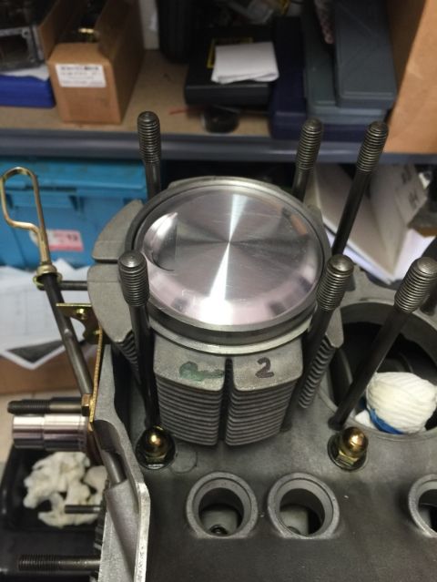
Base gaskets installed... I used the 1 mm gaskets
Install piston, without rings, to connecting rod... I did not bother to insert the circlips just in case...
Install cylinder...
Rinse and repeat for the other side...
And I wanted to have a photo where the gasket can be seen... going back to a question made earlier in the thread... you can see it and you can measure it in place...
Install the tool and torque down each nut to 20 ft-lbs...
I use the dial indicator to make it easier to be certain that I am at TDC... well, the truth is that I wanted to use the dial indicator, hhehehehe
I need to do this for all four pistons/cylinders... I will measure #1 again a couple of times, move to #2 and then setup to measure 3 & 4.
Back in a few...
Last edited by Wachuko; 02-08-2015 at 02:33 PM. Reason: Updated video link
 02-07-2015, 06:41 PM
#377
Professor of Pending Projects
Rennlist Member
Rennlist Member
Thread Starter
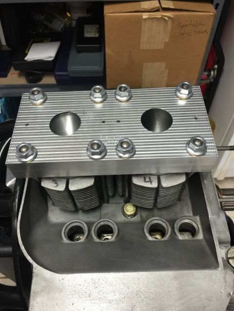
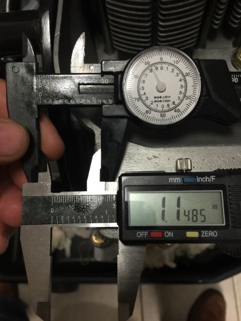
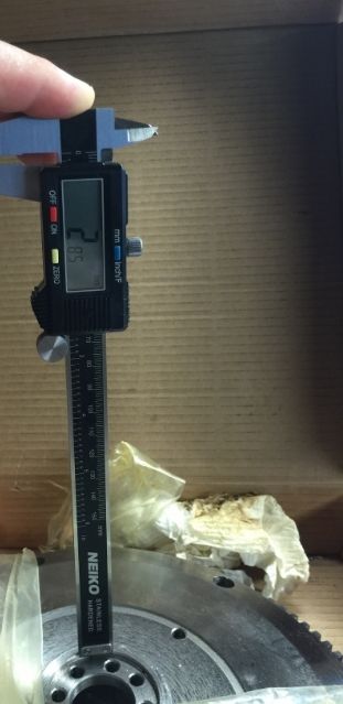
Opps.. I have to use what Ron sent me...those tiny holes you see in the tool is for the caliper rod to go in...
Here is were the hole leads to and you can see the rod from the caliper.
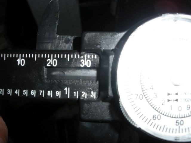
And if I am reading the caliper correctly... that would be:
#1 - 1.148"
#2 - 1.148"
If I understand the instructions correctly, the deck height is the number beyond 1" since the tool is 1.00" thick . That means that for 1 & 2 we have a deck height of:
#1 - .148"
#2 - .148"
Here is were the hole leads to and you can see the rod from the caliper.
And if I am reading the caliper correctly... that would be:
#1 - 1.148"
#2 - 1.148"
If I understand the instructions correctly, the deck height is the number beyond 1" since the tool is 1.00" thick . That means that for 1 & 2 we have a deck height of:
#1 - .148"
#2 - .148"
Last edited by Wachuko; 02-08-2015 at 02:34 PM.
02-08-2015, 03:02 PM
#378
Professor of Pending Projects
Rennlist Member
Rennlist Member
Thread Starter
Updated the video links in the previous posts... now with using the caliper that came in the tool kit and inserted in the correct location...
Rinse and repeat...
Measured 3 and 4 to validate that top are in plane... everything as 1 & 2 all good there.
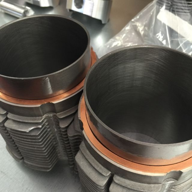
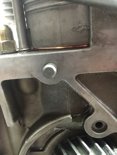
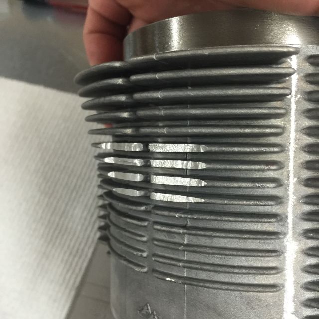
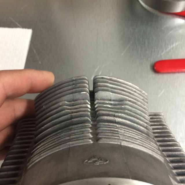
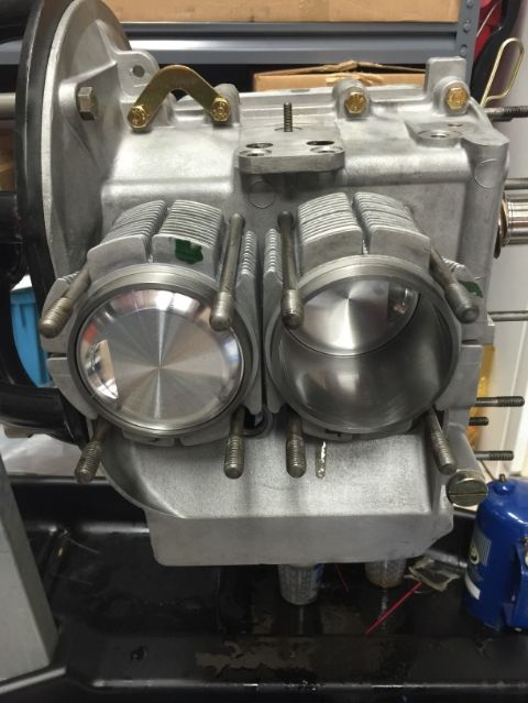
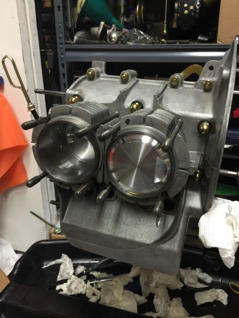
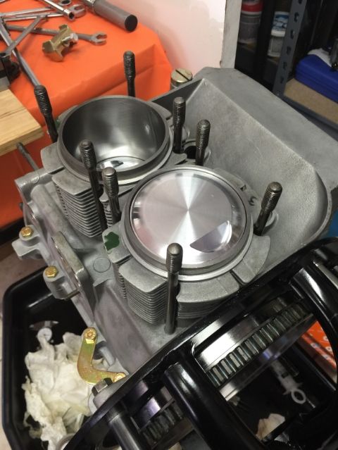
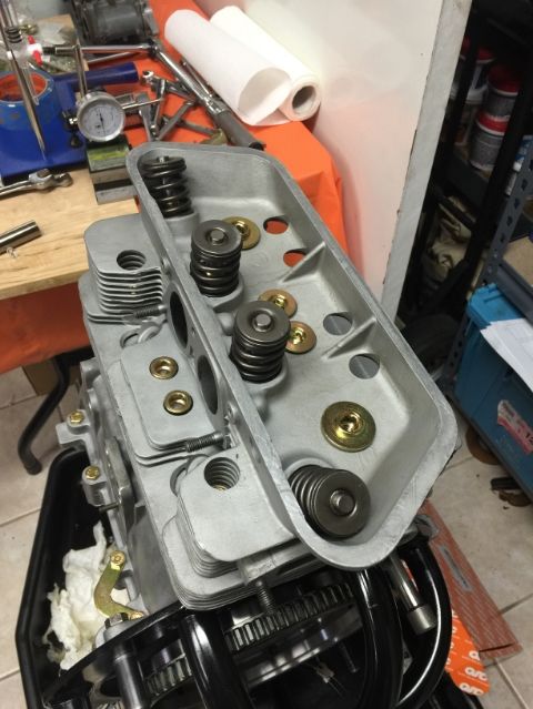
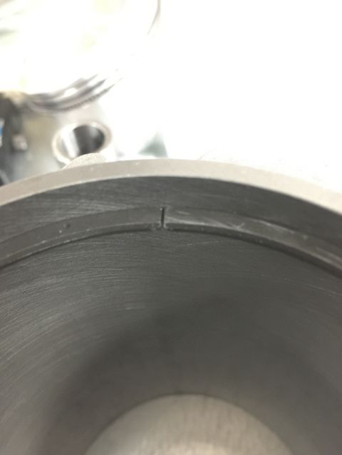
On to the next measurement. Removed the cylinders to install the base gasket and the pistons... took a better photo of the modification to the fins on #3
Also, as I installed the base gaskets, notice that it has notches that align with the ones in the pistons... not asymmetrical so be sure to align them correctly...
All piston rings removed...
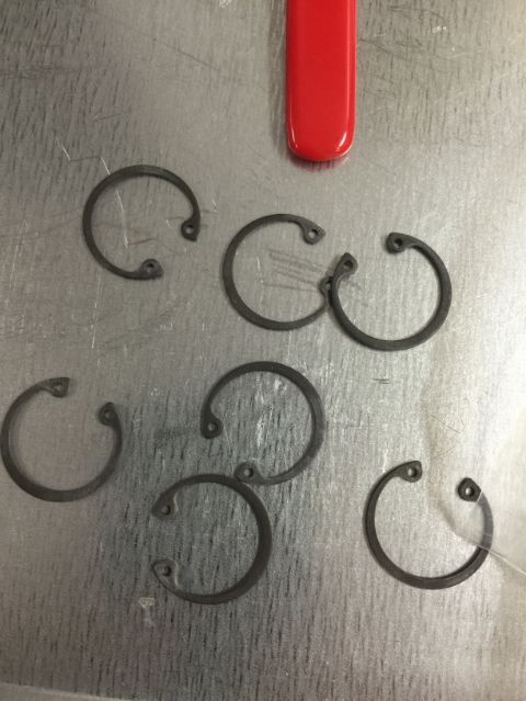
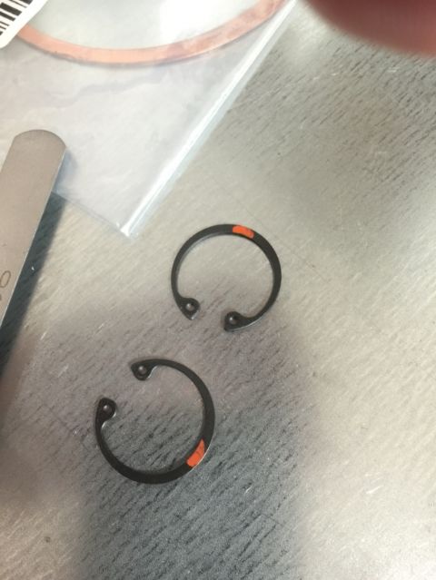
These circlips are different from what I took off the old engine... and the are the same on both sides. The old ones had a sharp edge on one side and a bit round on the other... these are sharp on both side.
Orientation of the circlips as described in the video...
Pistons 3 & 4 installed
Cylinders installed
Top End Tool installed and torqued to 20 ft-lbs
Seems that I have the same values as 1 & 2
So that gives me:
#1 = 1.148"
#2 = 1.148"
#3 = 1.148"
#4 = 1.148"
If I understand the instructions correctly, the deck height is the number beyond 1" since the tool is 1.00" thick . That means that for 1 & 2 we have a deck height of:
#1 = .148"
#2 = .148"
#3 = .148"
#4 = .148"
Now to get wet... measuring volume... back in a few, need to steal some play-doh from the kids...
Rinse and repeat...
Measured 3 and 4 to validate that top are in plane... everything as 1 & 2 all good there.
On to the next measurement. Removed the cylinders to install the base gasket and the pistons... took a better photo of the modification to the fins on #3
Also, as I installed the base gaskets, notice that it has notches that align with the ones in the pistons... not asymmetrical so be sure to align them correctly...
All piston rings removed...
These circlips are different from what I took off the old engine... and the are the same on both sides. The old ones had a sharp edge on one side and a bit round on the other... these are sharp on both side.
Orientation of the circlips as described in the video...
Pistons 3 & 4 installed
Cylinders installed
Top End Tool installed and torqued to 20 ft-lbs
Seems that I have the same values as 1 & 2
So that gives me:
#1 = 1.148"
#2 = 1.148"
#3 = 1.148"
#4 = 1.148"
If I understand the instructions correctly, the deck height is the number beyond 1" since the tool is 1.00" thick . That means that for 1 & 2 we have a deck height of:
#1 = .148"
#2 = .148"
#3 = .148"
#4 = .148"
Now to get wet... measuring volume... back in a few, need to steal some play-doh from the kids...
Last edited by Wachuko; 02-08-2015 at 03:43 PM.
02-09-2015, 01:00 PM
#379
Professor of Pending Projects
Rennlist Member
Rennlist Member
Thread Starter
Well... work has not allowed me to take the time required for the final measurement of volume... so I figured that I would try to work on Crankshaft End Play...
Since the old engine had three spacers of .32 mm... I think that I will need to buy a spacer. Porsche 912 are supposed to have just one spacer, not three like the do with VWs. I want to try and calculate the spacer before I do the test with the actual flywheel in place... at around 30.00 each, it is not like I can order a few just for fun...
If it matters...currently the crankshaft moves .011" (0.2794 mm)
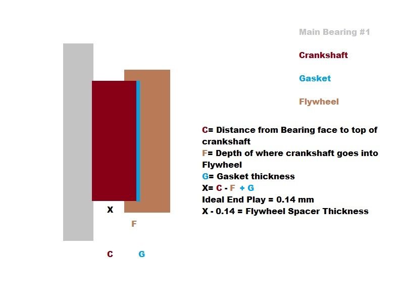
I measured F = 2.85 mm
I have a gasket, so I can measure G
I am missing the value for C. I will need to push out (towards the flywheel) the crankshaft and measure. That one is difficult to measure with the engine on the stand... hummm...
Took the engine out of the stand so that I could measure the distance from the bearing face to the tip of the crankshaft... 3.90 mm
That means... X=C-F+G=3.90-2.85+.15=1.20... 1.20-.14 = 1.06 or 1.05 mm for a .15 end play. Need to order that spacer.
Also, for the next measurement with Ron's tool, I need piston rings installed. I thought those were going to be easy to do... remove cylinders, remove pistons, install rings... so far easy... install pistons back in the rods, get the piston ring compressor, with everything oiled, try to insert cylinder.. easier written than done... but those are in. If I need to change that 1 mm base gasket that is there for something else, or to add.... I will have the pleasure of doing it all again... lol...
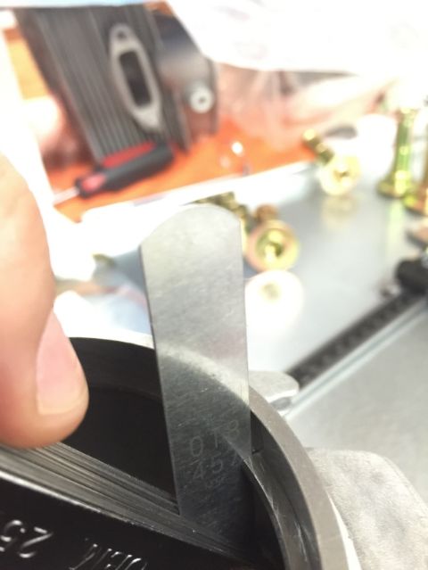
Someone reminded me that I need to measure piston ring gap...
Oh carp... Piston rings came installed when they shipped these... I had to take them out to mount them and perform the tests... Nope, I did not check for piston ring end gap... Documented on Page E63 or the workshop manual...
Applicable to all rings: Ring gap 0.3 - 0.45 mm (.012" - .018")
I guess that they come out again to test this first...
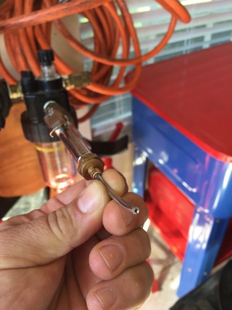
And here is one version of the filer you mentioned...

Thank you Peter!!
Since the old engine had three spacers of .32 mm... I think that I will need to buy a spacer. Porsche 912 are supposed to have just one spacer, not three like the do with VWs. I want to try and calculate the spacer before I do the test with the actual flywheel in place... at around 30.00 each, it is not like I can order a few just for fun...
If it matters...currently the crankshaft moves .011" (0.2794 mm)
I measured F = 2.85 mm
I have a gasket, so I can measure G
I am missing the value for C. I will need to push out (towards the flywheel) the crankshaft and measure. That one is difficult to measure with the engine on the stand... hummm...
Took the engine out of the stand so that I could measure the distance from the bearing face to the tip of the crankshaft... 3.90 mm
That means... X=C-F+G=3.90-2.85+.15=1.20... 1.20-.14 = 1.06 or 1.05 mm for a .15 end play. Need to order that spacer.
Also, for the next measurement with Ron's tool, I need piston rings installed. I thought those were going to be easy to do... remove cylinders, remove pistons, install rings... so far easy... install pistons back in the rods, get the piston ring compressor, with everything oiled, try to insert cylinder.. easier written than done... but those are in. If I need to change that 1 mm base gasket that is there for something else, or to add.... I will have the pleasure of doing it all again... lol...
Someone reminded me that I need to measure piston ring gap...
Jaime,
If you haven't, make sure you check ring gaps prior to installation on pistons (push ring into cylinder, square by pushing in a little further with piston, measure gap with feeler gauge, adjust as necessary by edge filing - there are special 'piston ring filers' ).
).
Peter
If you haven't, make sure you check ring gaps prior to installation on pistons (push ring into cylinder, square by pushing in a little further with piston, measure gap with feeler gauge, adjust as necessary by edge filing - there are special 'piston ring filers'
).Peter
Applicable to all rings: Ring gap 0.3 - 0.45 mm (.012" - .018")
I guess that they come out again to test this first...
And here is one version of the filer you mentioned...
Thank you Peter!!
02-10-2015, 08:49 AM
#380
Professor of Pending Projects
Rennlist Member
Rennlist Member
Thread Starter
So I asked my wife for some play-doh from the kids and she gave me this weird look and said... "Jaime, Daniela is 17 and Daniel is 12... they have not played with play-doh in over 7 years!"
So I pulled some cleaning clay to use to plug the tool.
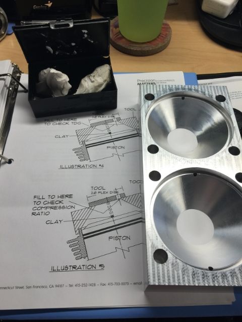
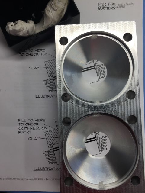
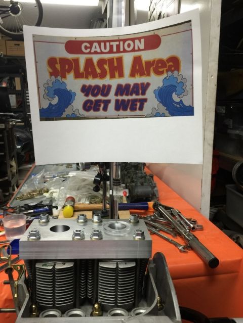
Okay... vaseline in place, tool torqued down... let's put some water in this puppy...
Head installed, hand tight, just to hold the cylinders from falling on the other side...
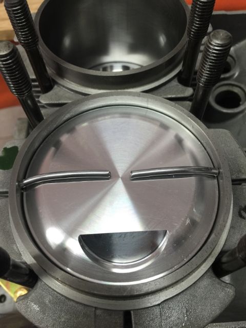
Okay... on to measuring the volume of the net chamber. The only thing that I would change from the instructions... well two things... one, you need a sign... (see photo), second, do yourself a favor, use a dial gauge and find TDC first... yeah... I measured the volume four times... first time I had the piston just below TDC... well, I filled the cylinder, left some space (that I thought was enough), and turned the camshaft to get the piston to TDC... woooshhhh!! Splash Mountain came to my mind... so after cleaning and drying everything, I got the dial gauge out, got the piston to TDC, filled it again and got the same measurements during the additional three tests...
Ron, don't think about it... just include it in the instructions
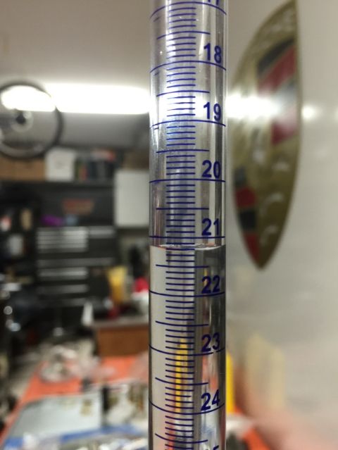
I do not have a 100 cc burette...it is a 50 cc unit. I emptied one and then the second one measured 21.2 cc - So that means 50 + 21.2 = 71.2 cc
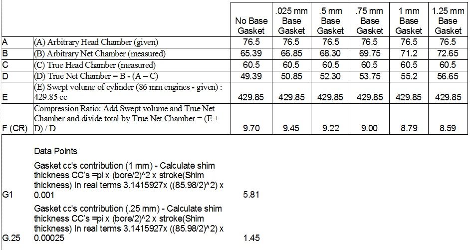
Now comes the math... but I need to know what compression ratio I need to be shooting for with this setup??? Then I can calculate back to the gaskets. From Ron La Dow and Dough Lehman, I have the following information (Ron, please confirm my math):
(A) Arbitrary Head Chamber (given): 76.5 cc
(B) Arbitrary Net Chamber (measured) : 71.2 cc
(C) True Head Chamber (measured) : 60.5 cc
(D) True Net Chamber = B - (A - C) = 71.2 - (75.5-60.5) = 71.2 - 16 = 55.2 cc
(E) Swept volume of cylinder (86 mm engines - given) : 429.85 cc
(F) Compression Ratio: Add Swept volume and True Net Chamber and divide total by True Net Chamber = (E + D) / D = 429.85 cc + 55.2 cc = 485.05 / 55.2 = 8.79 : 1
Calculate shim thickness CC’s - Volume of a cylinder is πr^2h In real terms 3.1415927 x (42.99^2) x 0.001 = 5.81 cc (I have had one 1 mm gasket during all these tests)
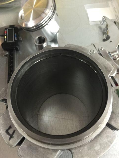
Measuring bore just to be sure:

Need to determine what compression ratio I should be shooting for so that I can work back the thickness of the base gasket...
So I pulled some cleaning clay to use to plug the tool.
Okay... vaseline in place, tool torqued down... let's put some water in this puppy...
Head installed, hand tight, just to hold the cylinders from falling on the other side...
Okay... on to measuring the volume of the net chamber. The only thing that I would change from the instructions... well two things... one, you need a sign... (see photo), second, do yourself a favor, use a dial gauge and find TDC first... yeah... I measured the volume four times... first time I had the piston just below TDC... well, I filled the cylinder, left some space (that I thought was enough), and turned the camshaft to get the piston to TDC... woooshhhh!! Splash Mountain came to my mind... so after cleaning and drying everything, I got the dial gauge out, got the piston to TDC, filled it again and got the same measurements during the additional three tests...
Ron, don't think about it... just include it in the instructions
I do not have a 100 cc burette...it is a 50 cc unit. I emptied one and then the second one measured 21.2 cc - So that means 50 + 21.2 = 71.2 cc
Now comes the math... but I need to know what compression ratio I need to be shooting for with this setup??? Then I can calculate back to the gaskets. From Ron La Dow and Dough Lehman, I have the following information (Ron, please confirm my math):
(A) Arbitrary Head Chamber (given): 76.5 cc
(B) Arbitrary Net Chamber (measured) : 71.2 cc
(C) True Head Chamber (measured) : 60.5 cc
(D) True Net Chamber = B - (A - C) = 71.2 - (75.5-60.5) = 71.2 - 16 = 55.2 cc
(E) Swept volume of cylinder (86 mm engines - given) : 429.85 cc
(F) Compression Ratio: Add Swept volume and True Net Chamber and divide total by True Net Chamber = (E + D) / D = 429.85 cc + 55.2 cc = 485.05 / 55.2 = 8.79 : 1
Calculate shim thickness CC’s - Volume of a cylinder is πr^2h In real terms 3.1415927 x (42.99^2) x 0.001 = 5.81 cc (I have had one 1 mm gasket during all these tests)
Measuring bore just to be sure:
Need to determine what compression ratio I should be shooting for so that I can work back the thickness of the base gasket...
Last edited by Wachuko; 02-10-2015 at 11:12 AM.
02-10-2015, 11:10 AM
#381
Professor of Pending Projects
Rennlist Member
Rennlist Member
Thread Starter
Jaime,
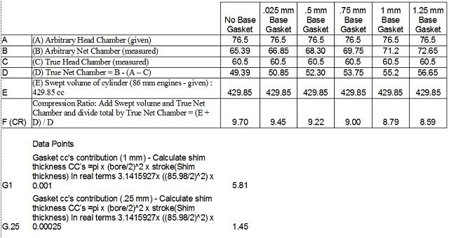
The correct value of your current 1mm base shim is 5.8cc not 6.75cc-each .25mm/.010 shim with 86mm bore pistons is 1.45cc. If you remove 1 yyshim (1.45cc) from your current volume of 55.2cc you now have 53.75cc and a CR of 8.997:1,remove 2 shims and your volume becomes 52.3cc with a CR of 9.21:1. Removing 2 shims will give you a very good CR number PROVIDED that the deck height is correct.
Just to humor an old man would you tape two pieces of thick solder on the piston tops at 6 and 12 o'clock,touching the cylinder wall,bump the engine over and report the measurement at the thinest part.
Tim Berardelli
Sure. I can do that.
Last edited by Wachuko; 02-11-2015 at 09:23 PM.
02-10-2015, 05:10 PM
#382
Professor of Pending Projects
Rennlist Member
Rennlist Member
Thread Starter
The solder I have is solid... I will stop by the local hardware store and get some flux core solder for the test. Article on this CE Deck Height
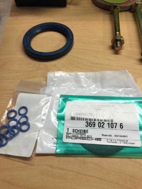
In the mean time... some more parts came in. And as Murphy saying goes... the one item that I needed is the one backordered... o-rings for the case... I called SMC and those should be here by Friday.
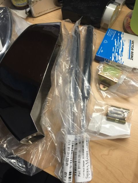
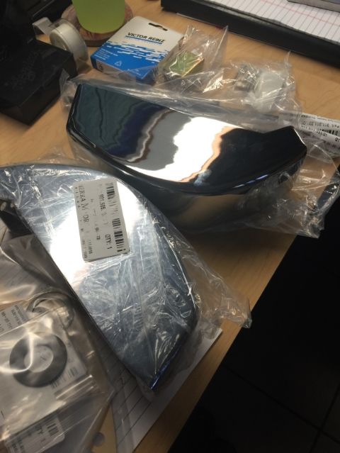
In the mean time... some more parts came in. And as Murphy saying goes... the one item that I needed is the one backordered... o-rings for the case... I called SMC and those should be here by Friday.
02-11-2015, 02:12 PM
#383
Professor of Pending Projects
Rennlist Member
Rennlist Member
Thread Starter
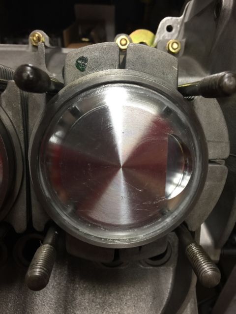
Here you go... just one cylinder. Do you want me to check all four? Seems and easy task if I need to do them all... I did not remove anything... so same 1 mm base cylinder gasket in place.
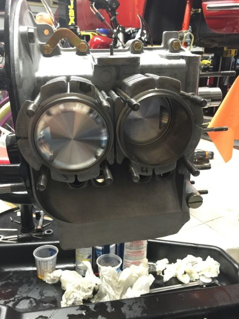
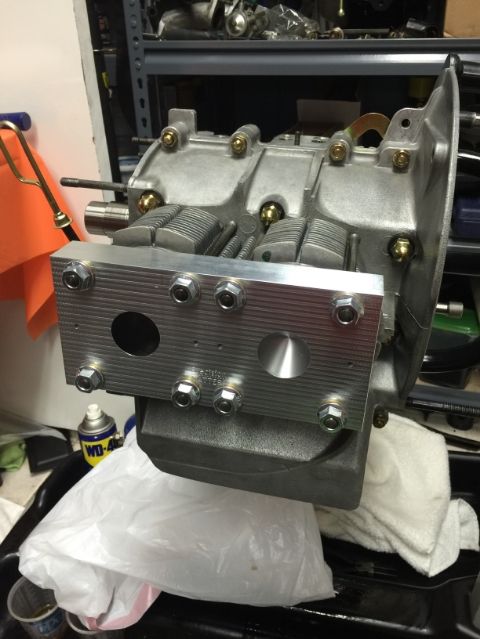
Short block ready
First, cut a few pieces of the solder and blow air though them to get rid of the acid flux...
Install on the piston... I used tape to hold them in place...
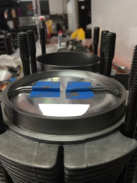
I lowered the piston a little bit... installed the head, torqued to 20 ft-lbs just for the test... I can do it again if I needed to torque it to factory specs 22 ft-lbs or as The Maestro recommends, 25 ft-lbs
I then turned the flywheel to get the piston to come up to TDC (I was looking via the sparkplug hole)
Removed the head...
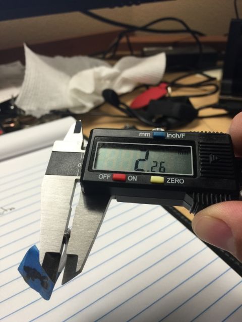
2.26... so this means that if I remove the 1mm I should be at 1.26mm? Or I should be between 1-1.5 mm with whatever base gasket that I plan to use?
Short block ready
First, cut a few pieces of the solder and blow air though them to get rid of the acid flux...
Install on the piston... I used tape to hold them in place...
I lowered the piston a little bit... installed the head, torqued to 20 ft-lbs just for the test... I can do it again if I needed to torque it to factory specs 22 ft-lbs or as The Maestro recommends, 25 ft-lbs
I then turned the flywheel to get the piston to come up to TDC (I was looking via the sparkplug hole)
Removed the head...
2.26... so this means that if I remove the 1mm I should be at 1.26mm? Or I should be between 1-1.5 mm with whatever base gasket that I plan to use?
02-11-2015, 03:20 PM
#384
Professor of Pending Projects
Rennlist Member
Rennlist Member
Thread Starter
Jaime,
Please remember the deck height /= the piston clearance. What you measured there is the piston clearance/"quench clearance".
I have to dig out the trig text to look up the name of the function, but from my notes, you have to remove 1.26 from the deck (vertical) height to reach 1.0 removed from the piston clearance, since it is measured at the 30* angle.
Put the other 'way round, you will tighten the piston/quench clearance by 80% of what you remove from the deck height.
So... with the above, and with this:
What would be the recommended CR that I should shoot for?
02-11-2015, 06:08 PM
#385
Professor of Pending Projects
Rennlist Member
Rennlist Member
Thread Starter
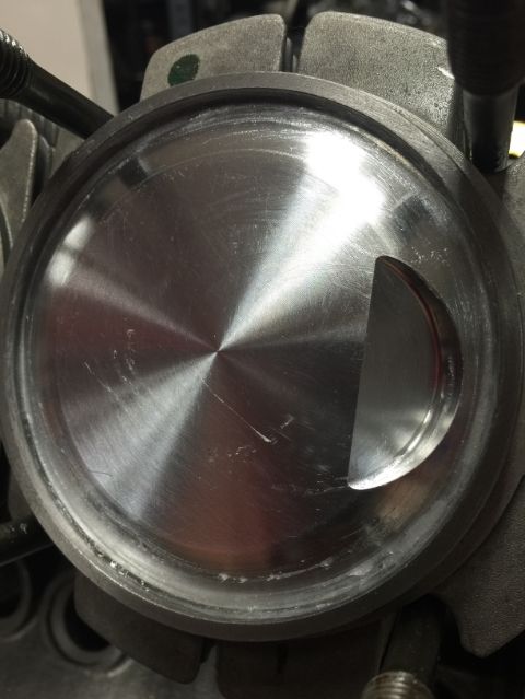
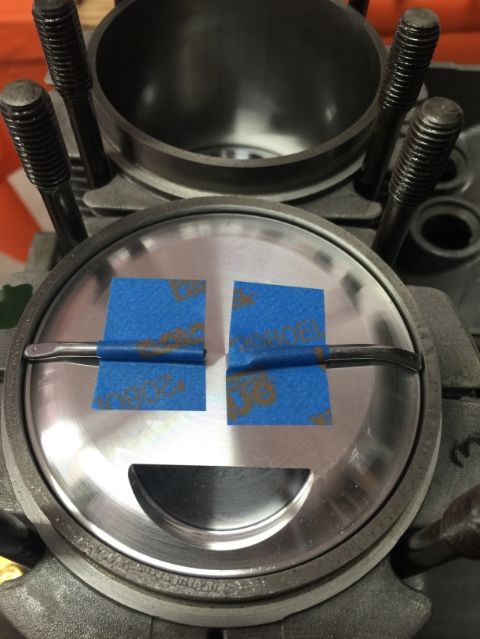
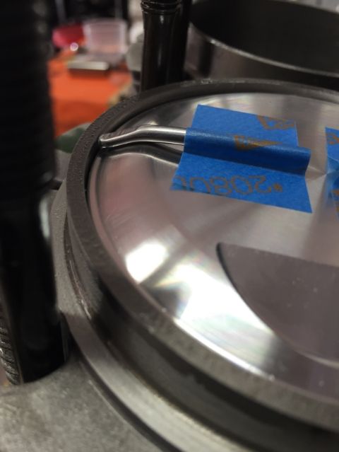
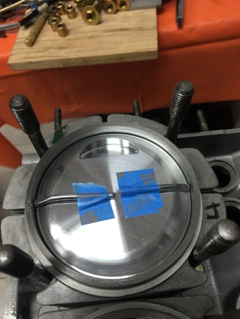
I was not satisfied with the first test... the angles on the solder, as those reached the walls of the cylinder, were not parallel to the cylinder walls... I did not make sure that the solder was completely touching all the top of the piston... anyway, I knew I could do better... so I did another run on 3 & 4... both sides again...
Tip of the solder cut at an angle to match with the cylinder wall
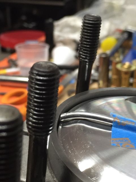
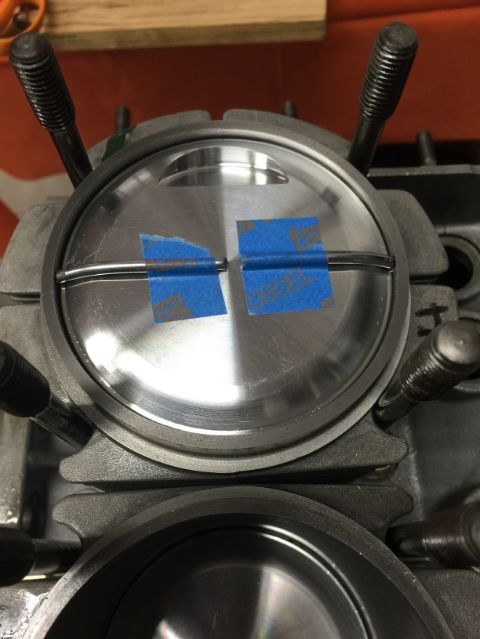
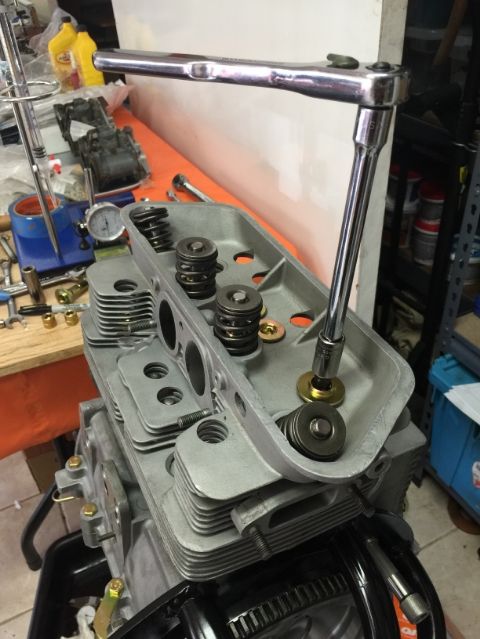
Torqued the head to 22 ft-lbs (do not call me out on the center nuts, I know both are not supposed to be the same... just easier to do this test with both being the same one as they go in nicely)
Turn flywheel...remove head... collect washers from the floor because you forgot about them...
Remove, repeat for cylinder #3
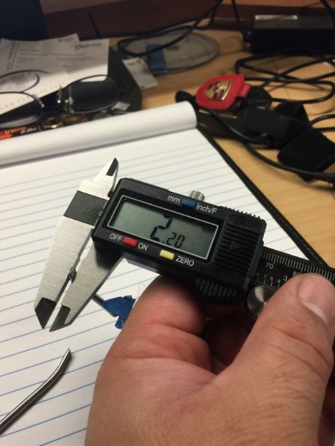
I got the same readings for both 3 & 4: 2.20 mm
Tip of the solder cut at an angle to match with the cylinder wall
Torqued the head to 22 ft-lbs (do not call me out on the center nuts, I know both are not supposed to be the same... just easier to do this test with both being the same one as they go in nicely)
Turn flywheel...remove head... collect washers from the floor because you forgot about them...
Remove, repeat for cylinder #3
I got the same readings for both 3 & 4: 2.20 mm
02-12-2015, 01:29 AM
#387
Professor of Pending Projects
Rennlist Member
Rennlist Member
Thread Starter
Moving on to a few pending chores.
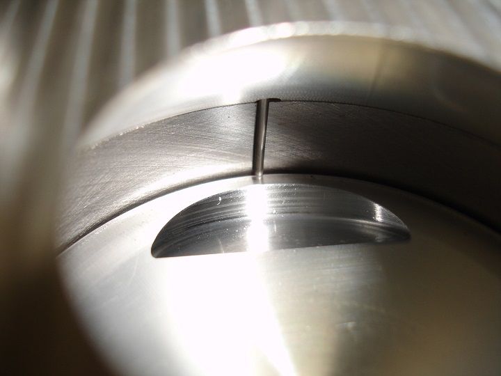
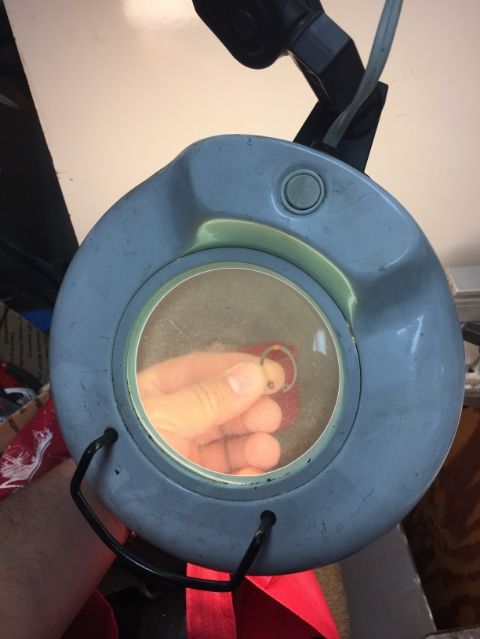
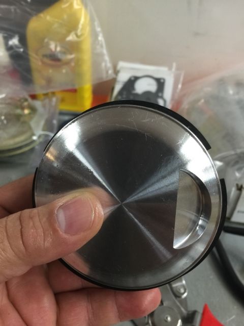
Removed the cylinder to check piston ring gaps and to make sure that the circlip on the pistons were facing with the sharp edge towards the outside. The first time I looked at them I could not tell sharp edge from the rolled edge... well sure enough (thank you Mike! ), I looked again closer with the help of an old magnifying glass... and there it was... put a orange mark on the sharp edge to make sure that it was facing out when installing.
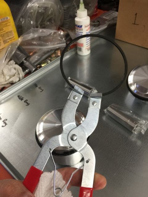
Remove pistons and remove piston rings.
Insert piston ring into cylinder and measure gap...
Install second piston ring and repeat...
And look at that!!
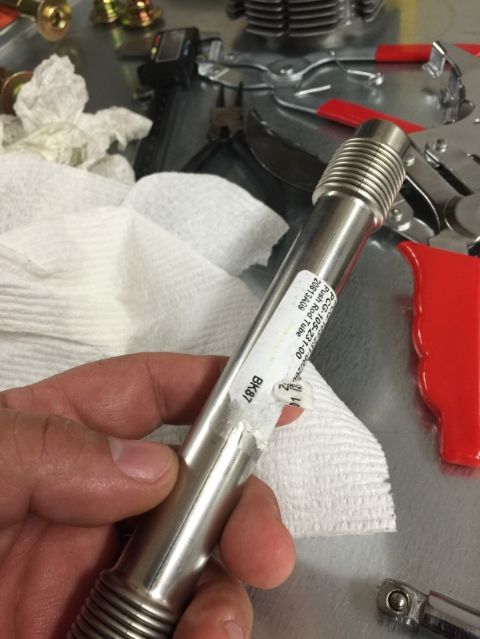
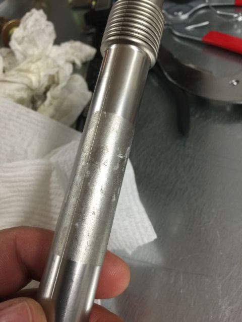
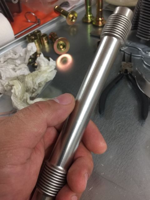
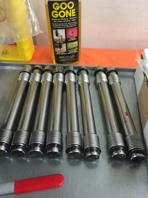
I hate these stickers!! Removing them is a pita... good thing I have not done my nails... remove them, grab some Goo Gone, clean clean clean... repeat 7 more times... I placed an orange mark on the seam to be able to see it quickly when installing. Recommendation is that the seam goes up.
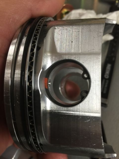
Install piston rings again
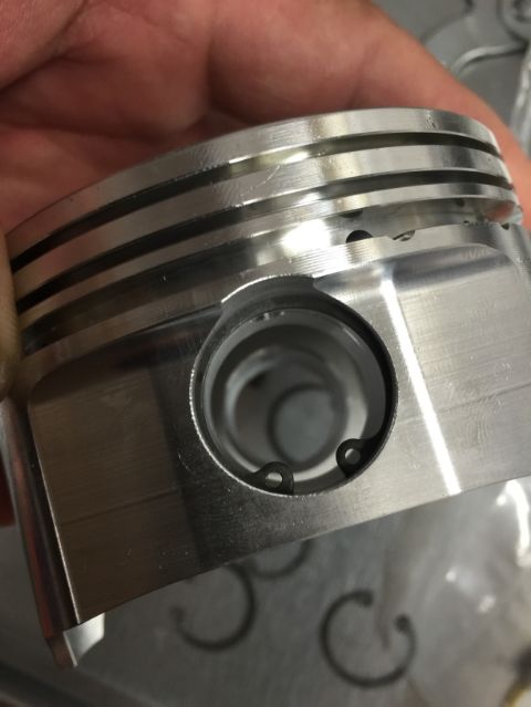
Circlip...open end of circlip faces the engine block.. sharp edge faces out...
Removed the cylinder to check piston ring gaps and to make sure that the circlip on the pistons were facing with the sharp edge towards the outside. The first time I looked at them I could not tell sharp edge from the rolled edge... well sure enough (thank you Mike! ), I looked again closer with the help of an old magnifying glass... and there it was... put a orange mark on the sharp edge to make sure that it was facing out when installing.
Remove pistons and remove piston rings.
Insert piston ring into cylinder and measure gap...
Install second piston ring and repeat...
And look at that!!
I hate these stickers!!
Removing them is a pita... good thing I have not done my nails... remove them, grab some Goo Gone, clean clean clean... repeat 7 more times... I placed an orange mark on the seam to be able to see it quickly when installing. Recommendation is that the seam goes up.Install piston rings again
Circlip...open end of circlip faces the engine block.. sharp edge faces out...
02-12-2015, 03:29 PM
#388
Professor of Pending Projects
Rennlist Member
Rennlist Member
Thread Starter
Waiting on the rear shim to do the end play test... that means that I can't install the front 3rd engine case piece... also waiting on the o-ring for the through bolt... So trying to do the small things that can be done while I wait...
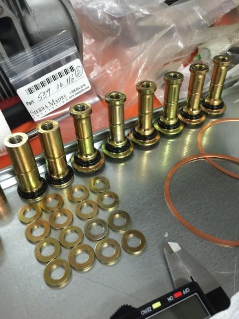
Installed the o-ring on the cylinder head nuts. Oiled them a little bit and slide them into place.
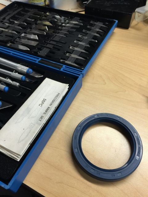
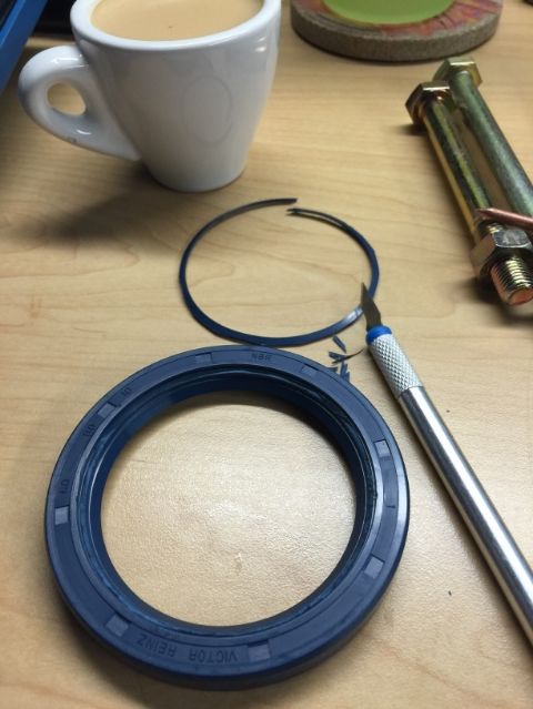
Trimmed the flywheel seal... I got a new one just in case I made a mistake with this one... it was basically to remove the outer most seal ring.
Installed the o-ring on the cylinder head nuts. Oiled them a little bit and slide them into place.
Trimmed the flywheel seal... I got a new one just in case I made a mistake with this one... it was basically to remove the outer most seal ring.
02-14-2015, 10:46 AM
#389
Professor of Pending Projects
Rennlist Member
Rennlist Member
Thread Starter
Looks like I will be able to set end play today!!
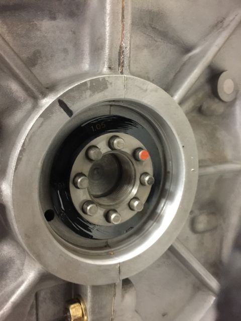
Okay, so I replaced the o-rings on the through bolt. Torqueq that back to specs. Carefully checked the torque on the rest of the nuts (I did not wanted to disturb the case...)... those did not move. Nice...
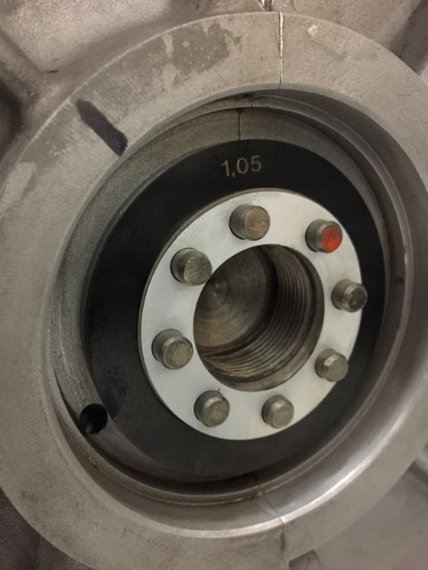
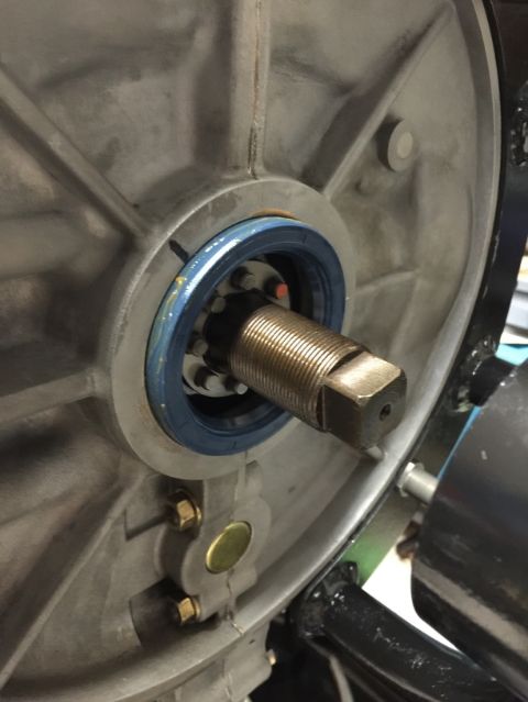
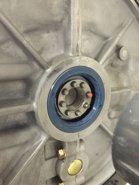
Then moved to the checking end play. Started by using the 1.05 flywheel spacer (I ended up ordering 1.00 mm and 1.05 mm). Also used a new flywheel metal gasket (old one was just too beat up...). The orange dot is to make it easier to align the flywheel... even knowing where those two holes, that are closer, are... first time installing it was a pita... now it goes in the right spot the first time. Knowing that it will come out one more time to install the seal, well, I appreciate having that mark there.
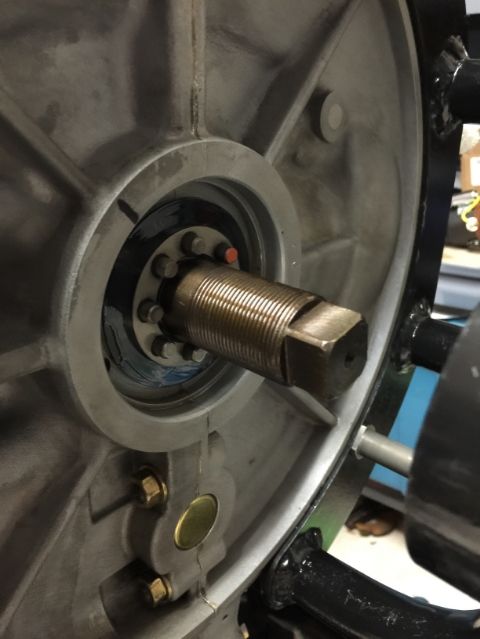
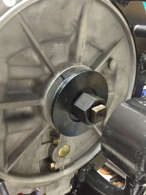
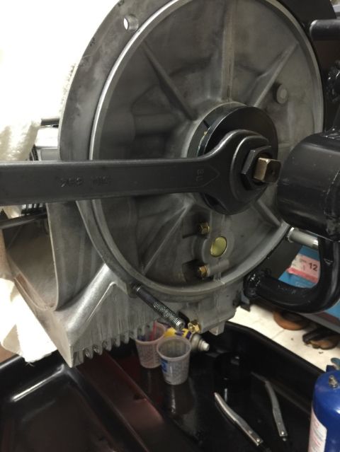
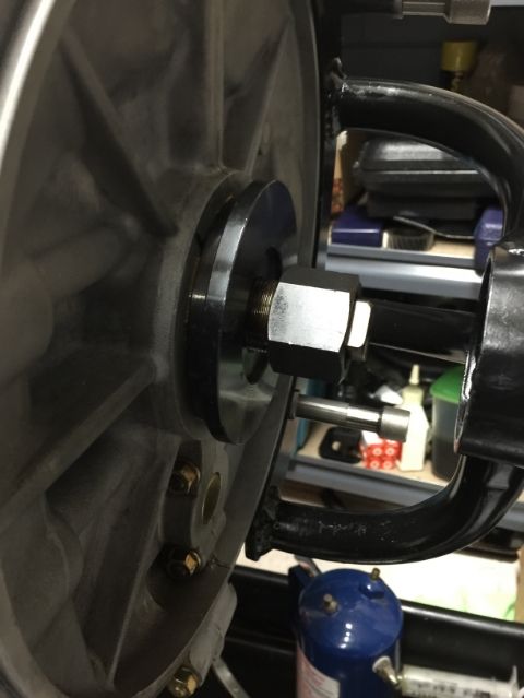
Torqued the gland nut to 360 lbs/ft.
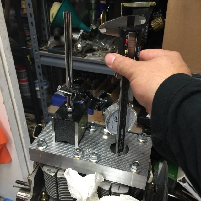
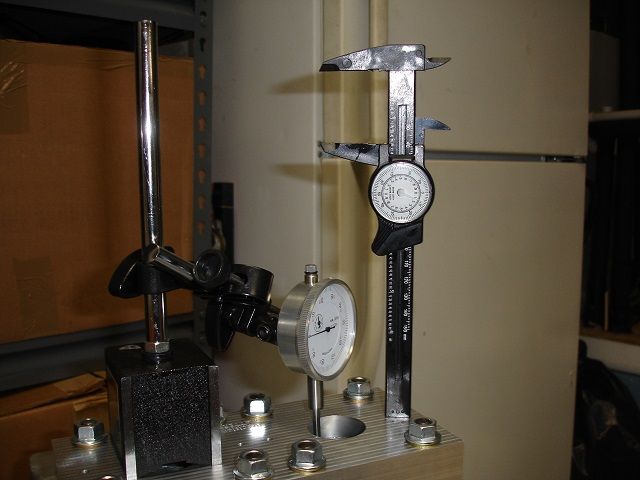
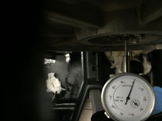
Install the gauge. I placed it on the engine stand arm to avoid any movements that would come from the arm moving on the stand... Zero it out.. and started to measure.
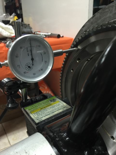
Push in, out, in, out, in, out...
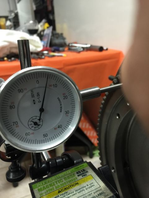
Took a couple of videos... This was slight pressure with the thumbs.
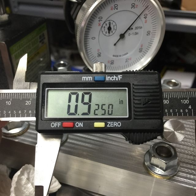
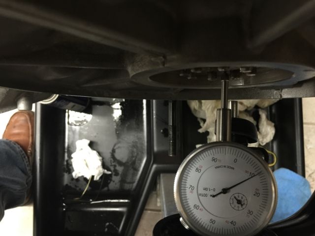
Closer please...
Okay, so I replaced the o-rings on the through bolt. Torqueq that back to specs. Carefully checked the torque on the rest of the nuts (I did not wanted to disturb the case...)... those did not move. Nice...
Then moved to the checking end play. Started by using the 1.05 flywheel spacer (I ended up ordering 1.00 mm and 1.05 mm). Also used a new flywheel metal gasket (old one was just too beat up...). The orange dot is to make it easier to align the flywheel... even knowing where those two holes, that are closer, are... first time installing it was a pita... now it goes in the right spot the first time. Knowing that it will come out one more time to install the seal, well, I appreciate having that mark there.
Torqued the gland nut to 360 lbs/ft.
Install the gauge. I placed it on the engine stand arm to avoid any movements that would come from the arm moving on the stand... Zero it out.. and started to measure.
Push in, out, in, out, in, out...
Took a couple of videos... This was slight pressure with the thumbs.
Closer please...
02-14-2015, 10:49 AM
#390
Professor of Pending Projects
Rennlist Member
Rennlist Member
Thread Starter
Well... I tried the 1.0 mm flywheel spacer... end play was out of spec... so 1.05 went back in. This time, put a little bit of oil on both faces of the spacer...
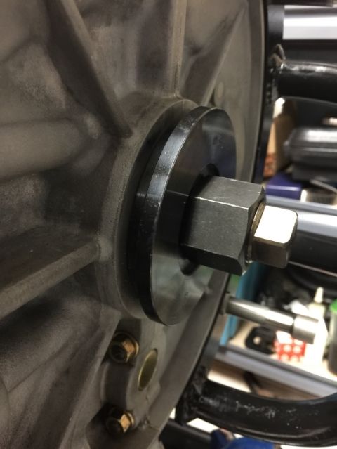
Seal install tool
Done! I will now install a new metal crankshaft gasket and install the flywheel... gland nut with a little bit of red loctite and torqued to 425 lbs/ft as The Maestro recommends (even if the workshop manual asks for 268 lbs/ft).
Seal install tool
Done! I will now install a new metal crankshaft gasket and install the flywheel... gland nut with a little bit of red loctite and torqued to 425 lbs/ft as The Maestro recommends (even if the workshop manual asks for 268 lbs/ft).