
My 1967 912 Build Thread
 02-19-2015, 11:55 PM
#406
Professor of Pending Projects
Rennlist Member
Rennlist Member
Thread Starter
Now I know how my wife feels...
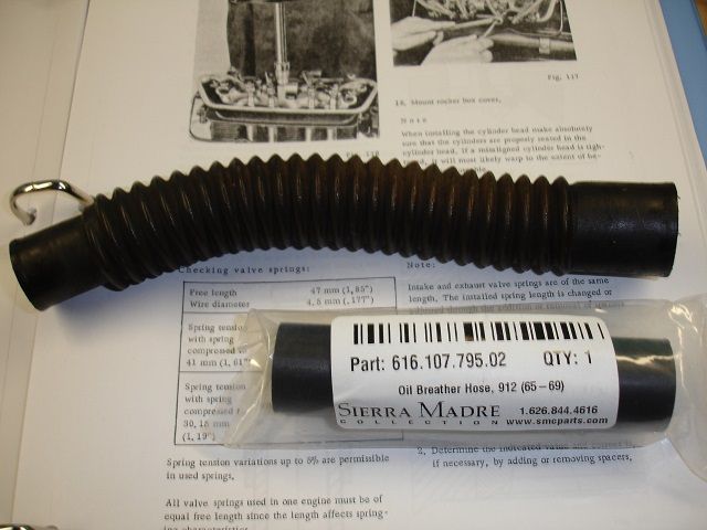
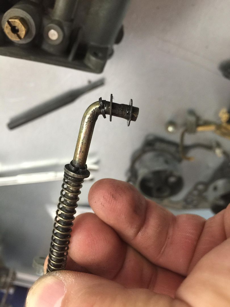
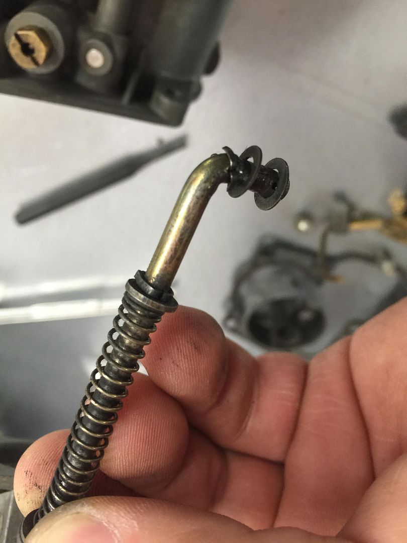
I need the one on top, got the one in the bottom... I needed Part Number: 616.107.795.01
I ended up ordering Part Number: 616.107.795.02 thinking that it superseded 616.107.795.01. But in fact this 616.107.795.02 is a much shorter hose than the one I need...
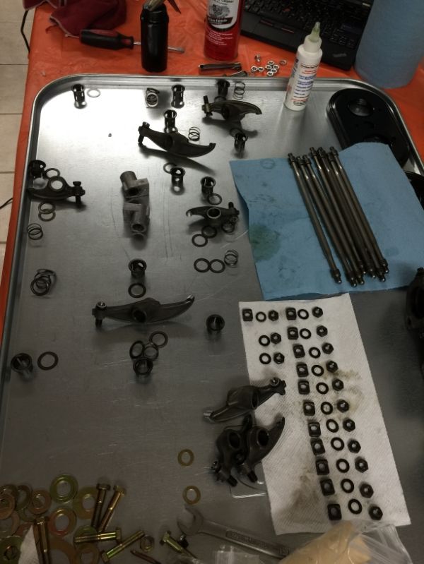
On positive news... 10 x 18 mm spring washers came in
On the rocker arm shafts. Email sent to the folks at http://www.partsklassik.com/ .... even after closing hours, got an email from Kurt answering my questions on the replacement shafts versus restoring mine with hardchrome finish... Restoration of mine will bring them back to specs. Going with their exchange program. Sending mine via Priority Mail tonight!

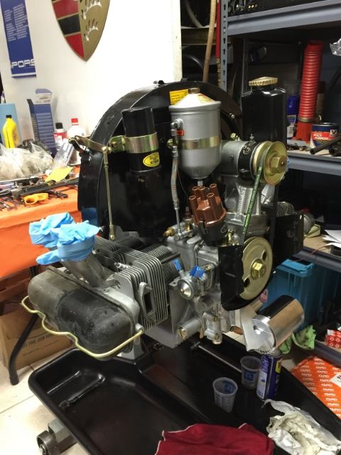
The expense (not budget...but what has been...!?) means that I will paint most of the engine tins instead of powder coating... only powder coating the big front and side trays and engine mount bar. I will drop those at the shop tomorrow.
Returning oil vent hose and ordering correct one...
Not much to do in the garage for now... maybe get the generator wires cleaned up, install the rubber boots, and the expandable cable sleeving that I want to use to better protect them from the heat...
Enough for tonight... must get some sleep...
I need the one on top, got the one in the bottom... I needed Part Number: 616.107.795.01
I ended up ordering Part Number: 616.107.795.02 thinking that it superseded 616.107.795.01. But in fact this 616.107.795.02 is a much shorter hose than the one I need...
On positive news... 10 x 18 mm spring washers came in
On the rocker arm shafts. Email sent to the folks at http://www.partsklassik.com/ .... even after closing hours, got an email from Kurt answering my questions on the replacement shafts versus restoring mine with hardchrome finish... Restoration of mine will bring them back to specs. Going with their exchange program. Sending mine via Priority Mail tonight!
The expense (not budget...but what has been...!?) means that I will paint most of the engine tins instead of powder coating... only powder coating the big front and side trays and engine mount bar. I will drop those at the shop tomorrow.
Returning oil vent hose and ordering correct one...
Not much to do in the garage for now... maybe get the generator wires cleaned up, install the rubber boots, and the expandable cable sleeving that I want to use to better protect them from the heat...
Enough for tonight... must get some sleep...
Last edited by Wachuko; 02-20-2015 at 04:22 PM.
 02-20-2015, 02:08 AM
#407
Professor of Pending Projects
Rennlist Member
Rennlist Member
Thread Starter
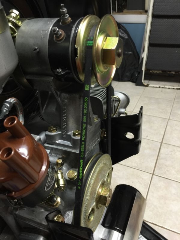
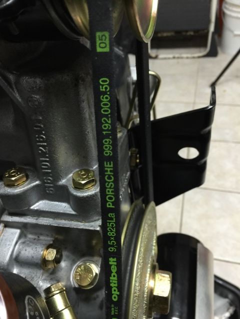
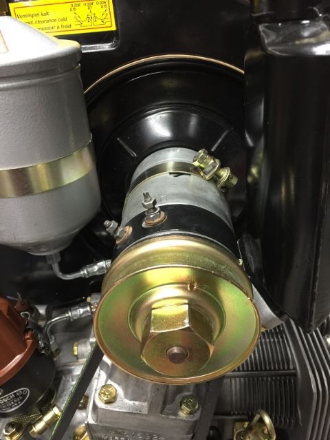
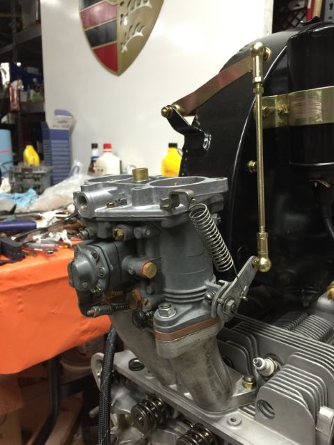
This came in today and I just had to install it before going to bed... silly, I know... a belt is a belt, is a belt...
I have to decide on the color of the valve covers...
This task will have to wait a little bit...
I have to decide on the color of the valve covers...
This task will have to wait a little bit...
02-20-2015, 04:24 PM
#409
Professor of Pending Projects
Rennlist Member
Rennlist Member
Thread Starter

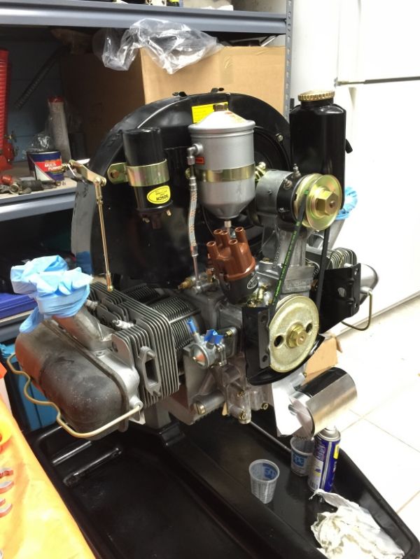
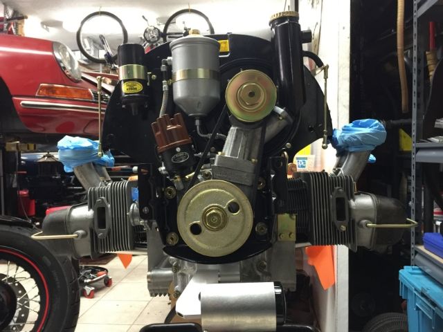
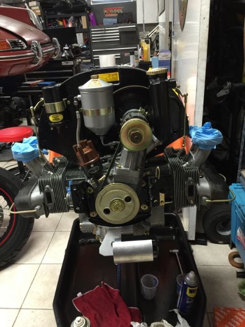
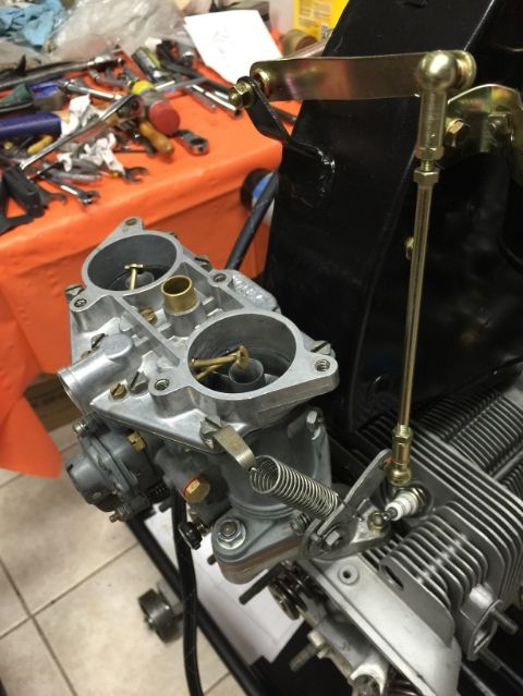
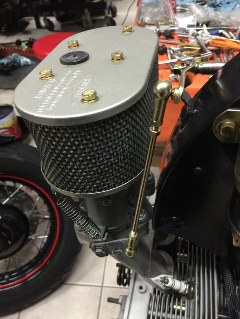
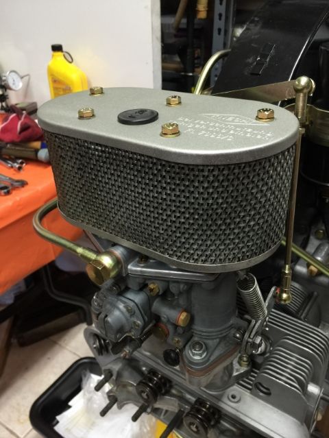
And let's add a few more photos just for the fun of it... still need to decide on the color of the valve covers...
 02-23-2015, 08:02 AM
#410
Professor of Pending Projects
Rennlist Member
Rennlist Member
Thread Starter
Here we go...
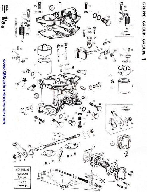
http://www.356carburetorrescue.com/partsdiagrams.html
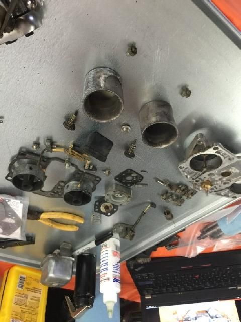
Well... photo overload!
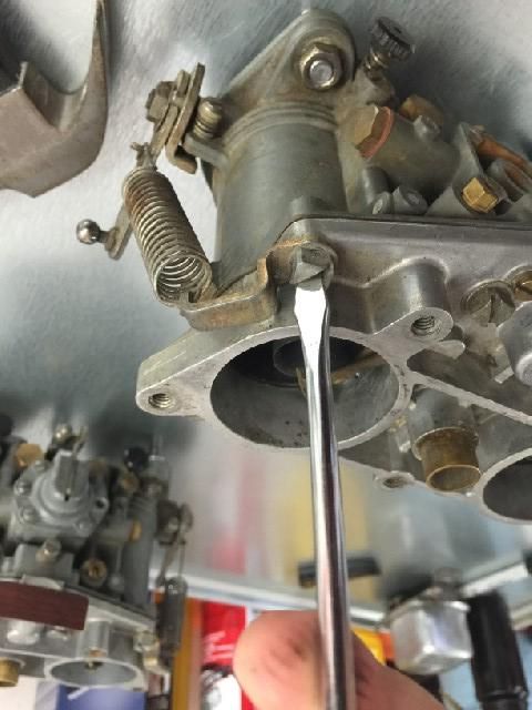
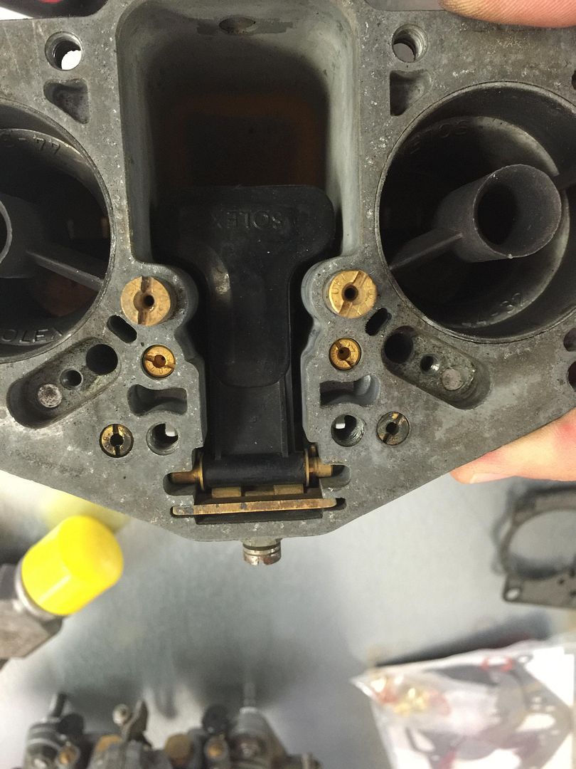
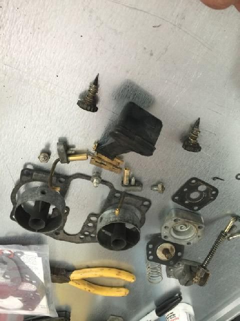
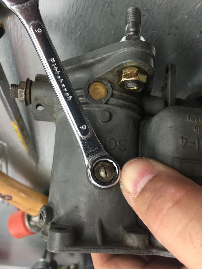
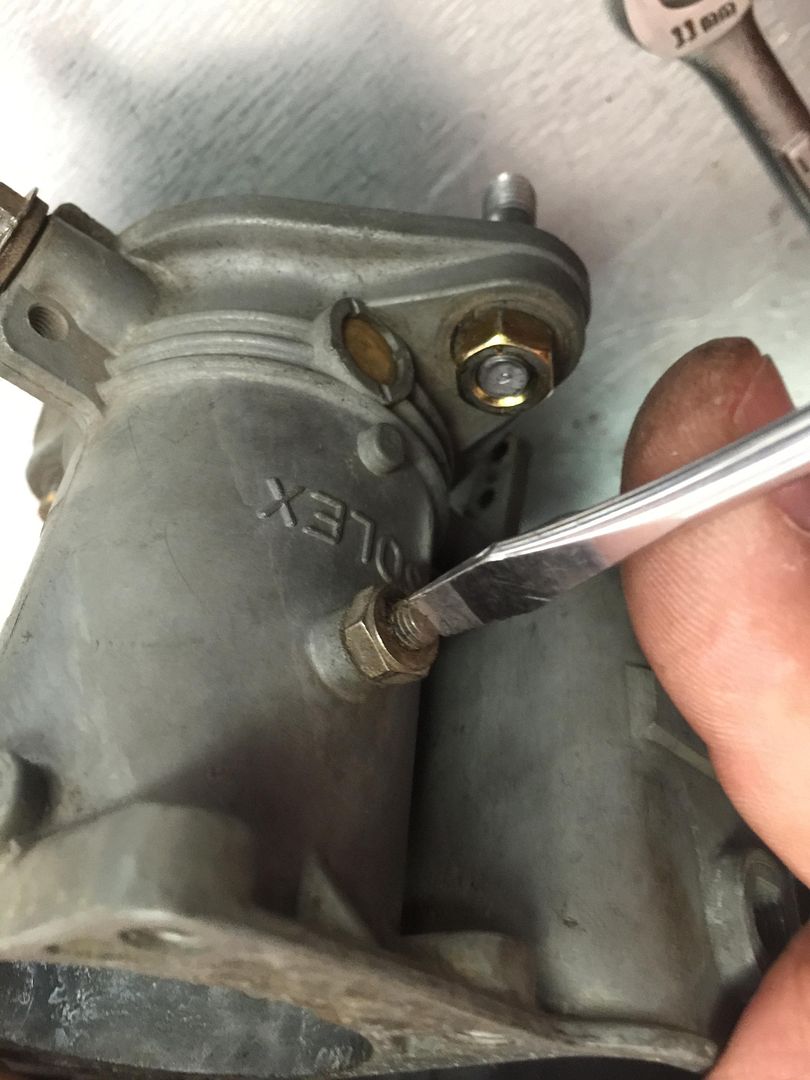
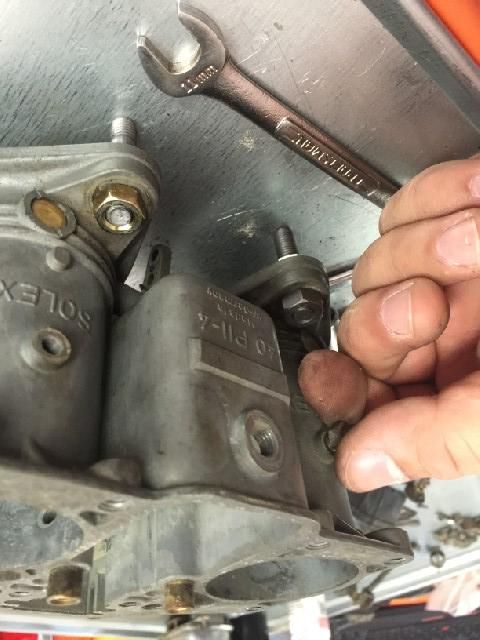
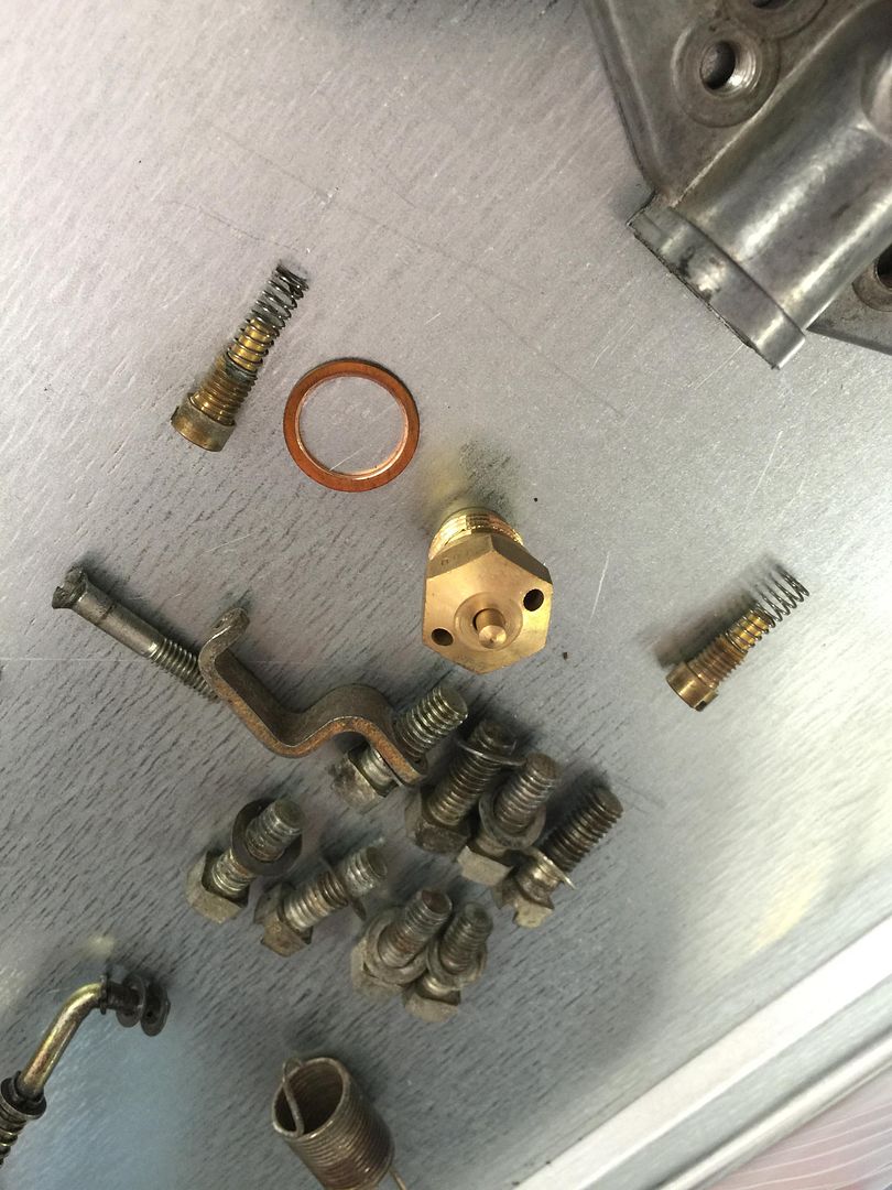
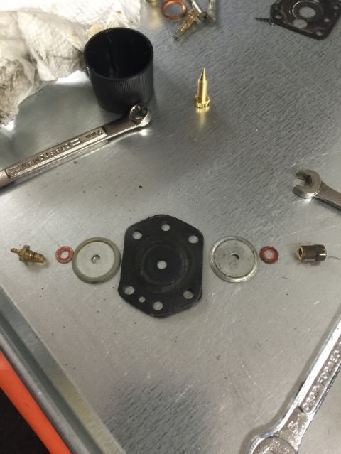
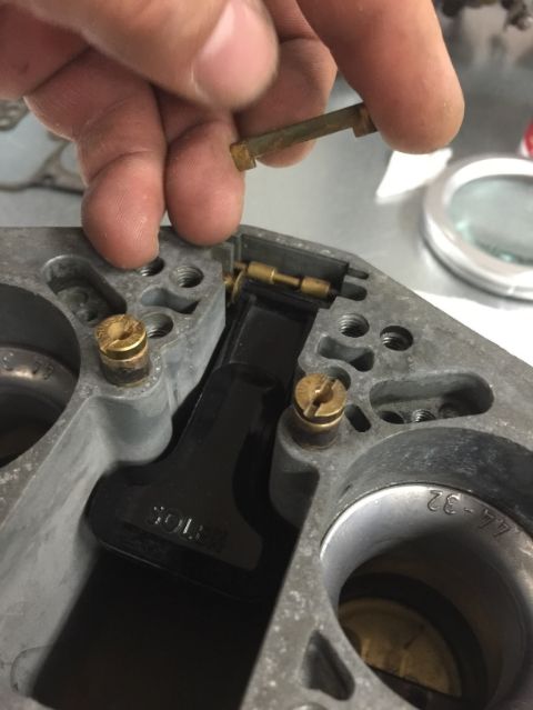
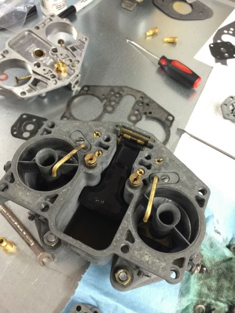
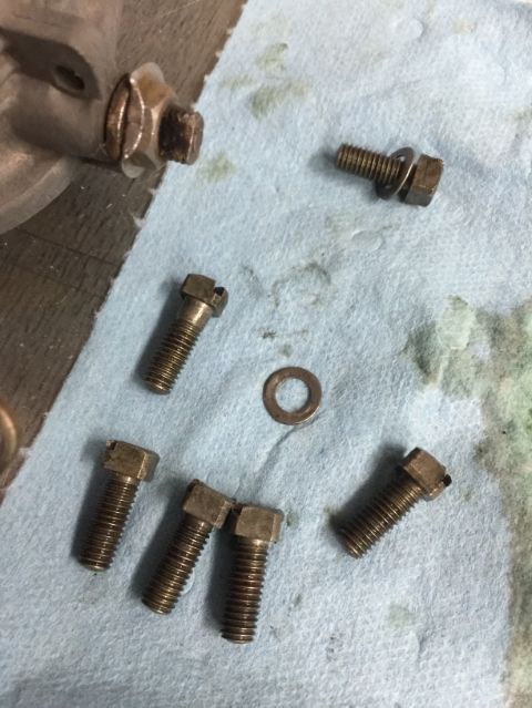
Remove the two small and four longer bolts
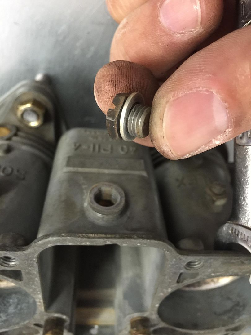
Remove the small split pin (I will replace as I doubt it will sustain being bent again... ). There are two very small washers in it... just be aware and remember to take them out...not like some people that need to put on 3.00 glasses for this task instead of the normal 1.50 and did not see them until you flip the carburetor around... and then you only find one and try to figure out where the heck it came from... and it is then that you see the other one still stuck to the carburetor, held in place by the old grease it had... not that it happened to me, just something I read somewhere
And we are moving people...keep moving...
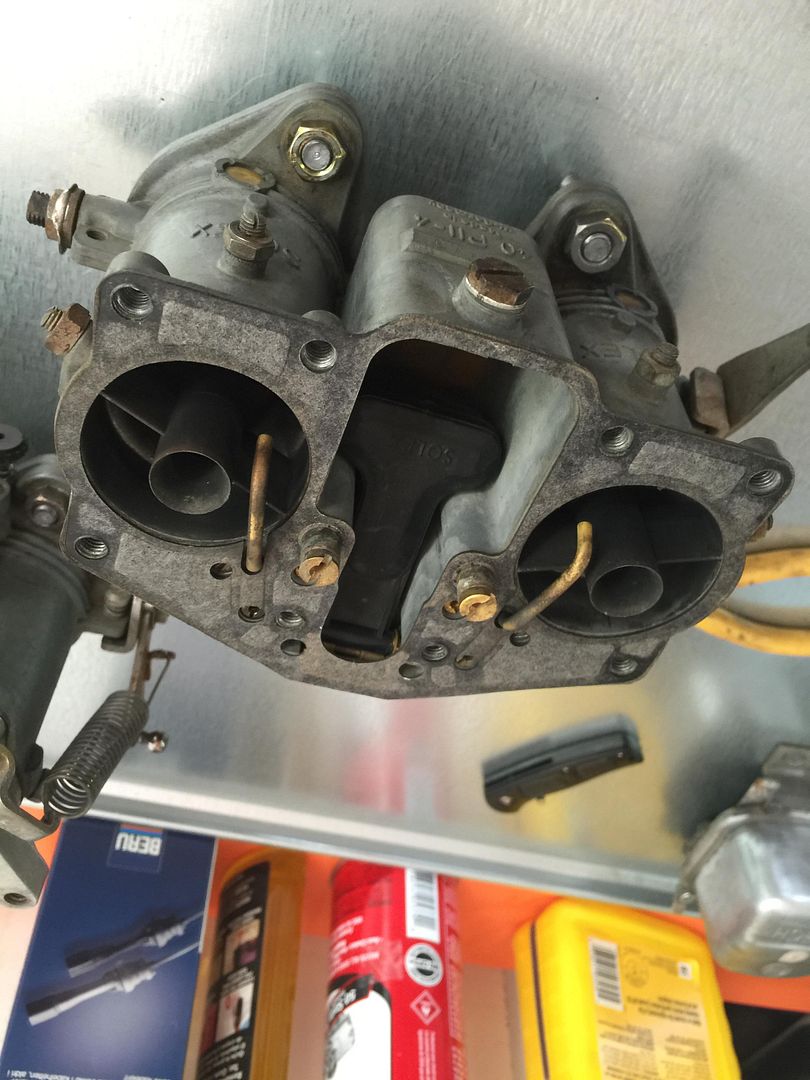
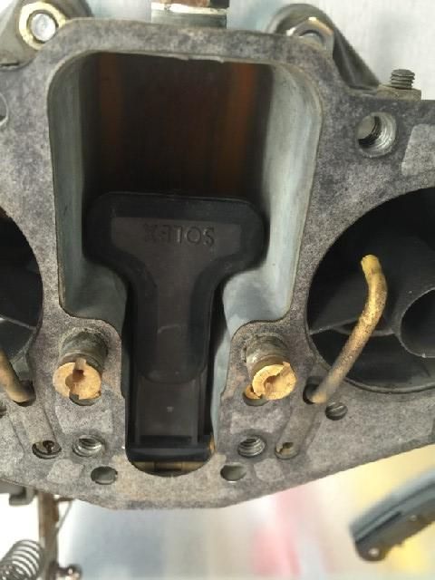
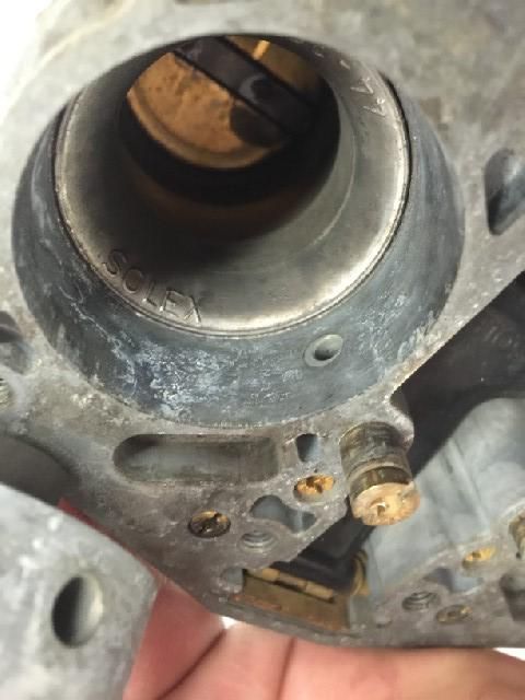
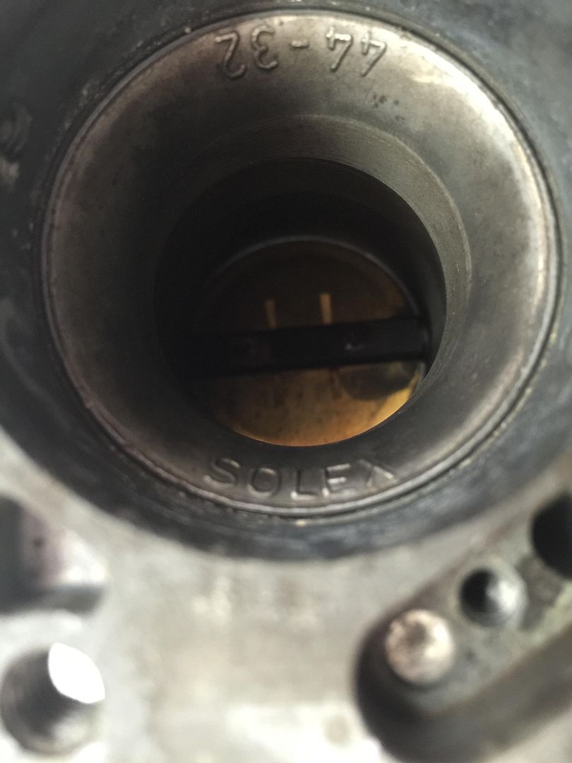
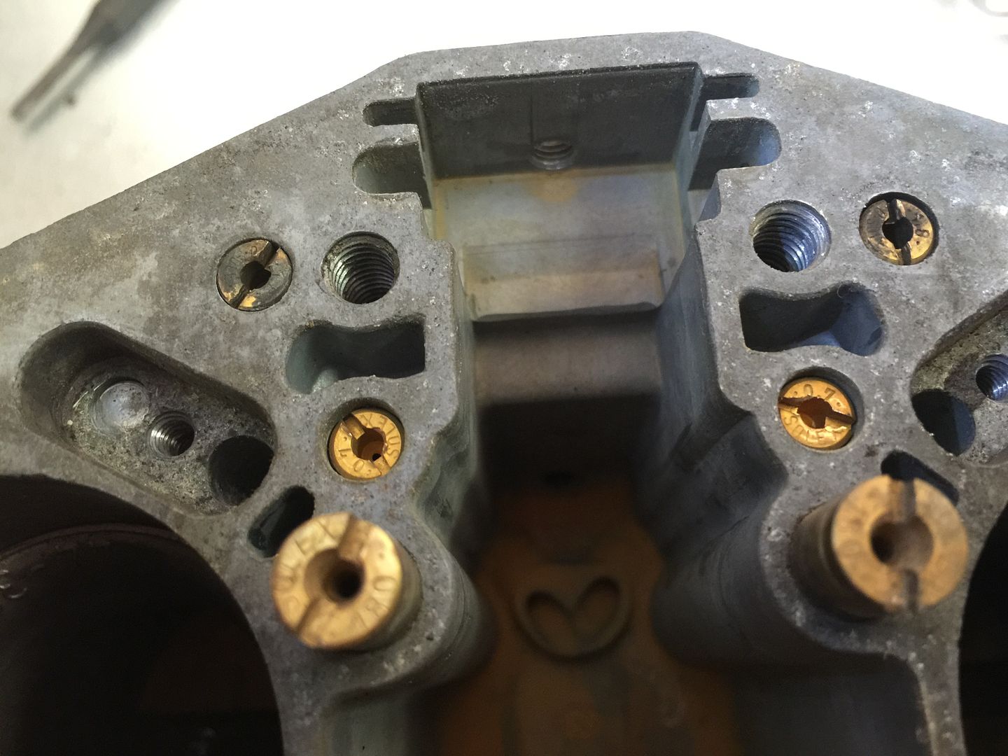
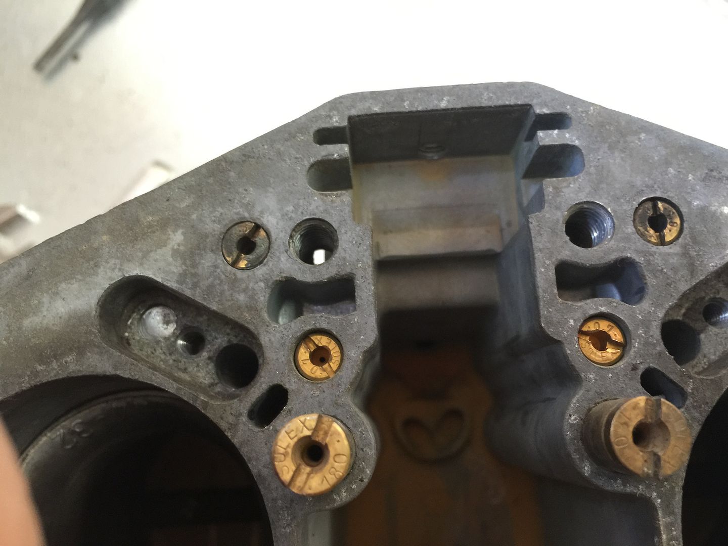
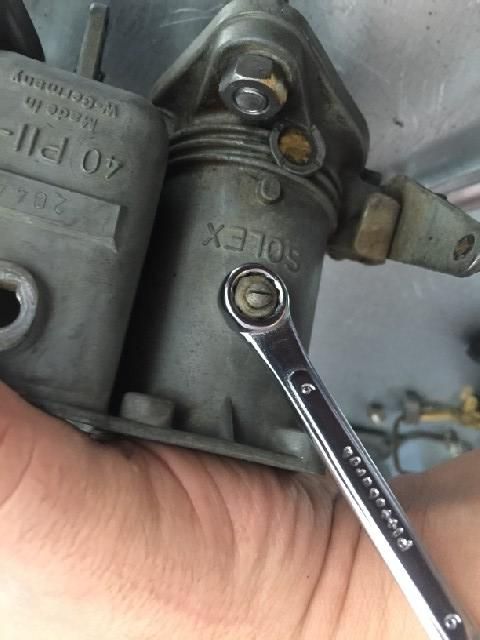
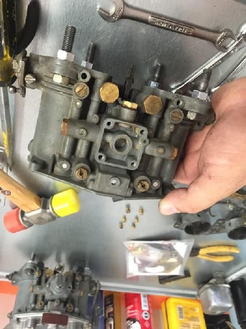
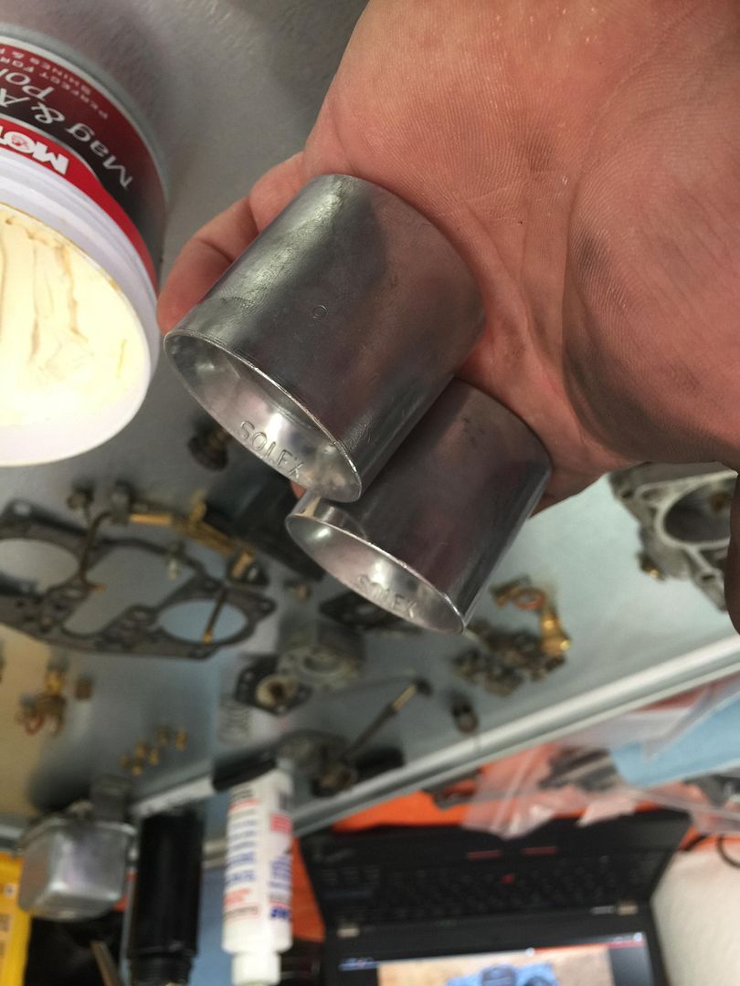
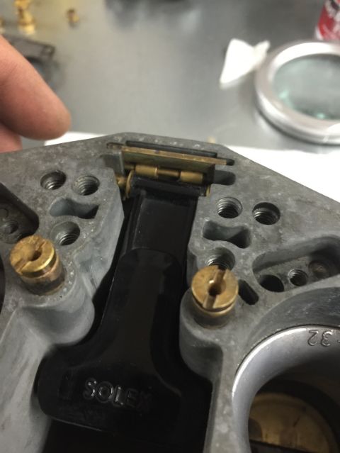
Some of these are so that I can zoom in on the original photo and read the numbers... sorry for what it seems a lot of photos of the same stuff...
Real mean do not use hand lotion, so shut up!
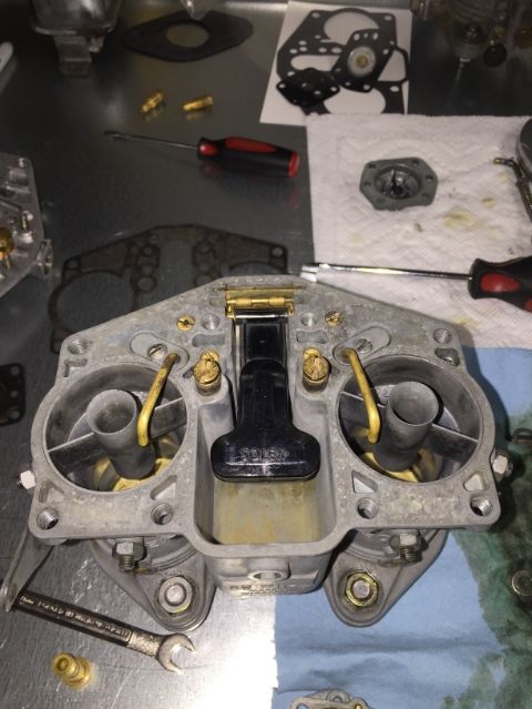
Other side
http://www.356carburetorrescue.com/partsdiagrams.html
Well... photo overload!
Remove the two small and four longer bolts
Remove the small split pin (I will replace as I doubt it will sustain being bent again... ). There are two very small washers in it... just be aware and remember to take them out...not like some people that need to put on 3.00 glasses for this task instead of the normal 1.50 and did not see them until you flip the carburetor around... and then you only find one and try to figure out where the heck it came from... and it is then that you see the other one still stuck to the carburetor, held in place by the old grease it had... not that it happened to me, just something I read somewhere
And we are moving people...keep moving...
Some of these are so that I can zoom in on the original photo and read the numbers... sorry for what it seems a lot of photos of the same stuff...
Real mean do not use hand lotion, so shut up!
Other side
Last edited by Wachuko; 02-23-2015 at 08:31 AM.
 02-23-2015, 08:05 AM
#412
Professor of Pending Projects
Rennlist Member
Rennlist Member
Thread Starter
And more...
Parts are starting to pile up...
Keep your eye on the ball...
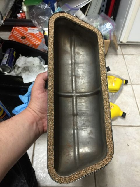
That is a lot of dirt...
Forgot to take this out when I took out the cover
Parts are starting to pile up...
Keep your eye on the ball...
That is a lot of dirt...
Forgot to take this out when I took out the cover
02-23-2015, 08:06 AM
#413
Professor of Pending Projects
Rennlist Member
Rennlist Member
Thread Starter
the easy stuff first...carb cleaner first, then some mothers...
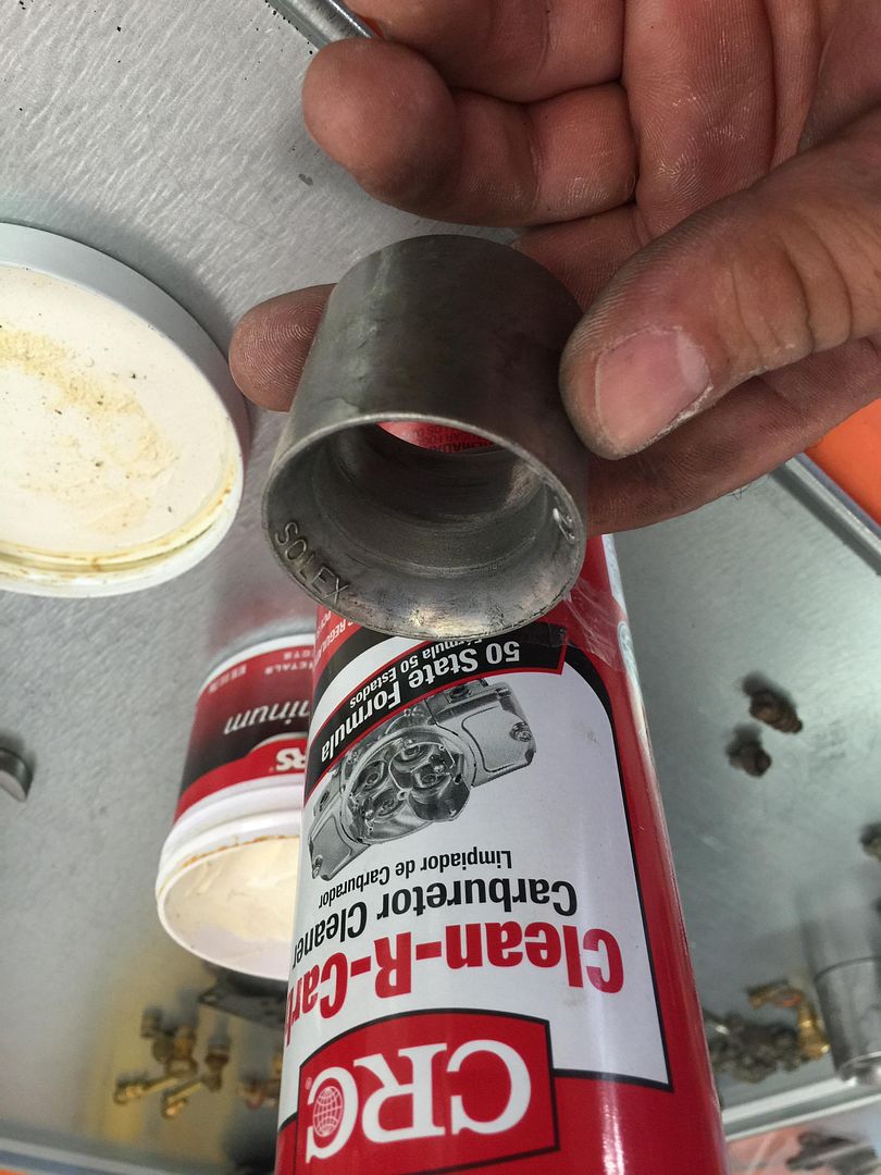
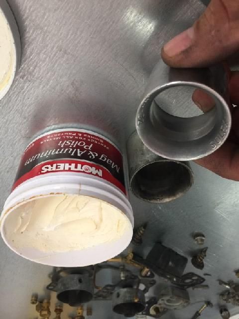
Then carb cleaner again... done...
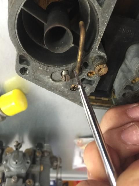
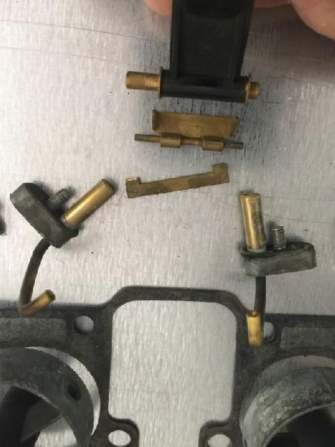
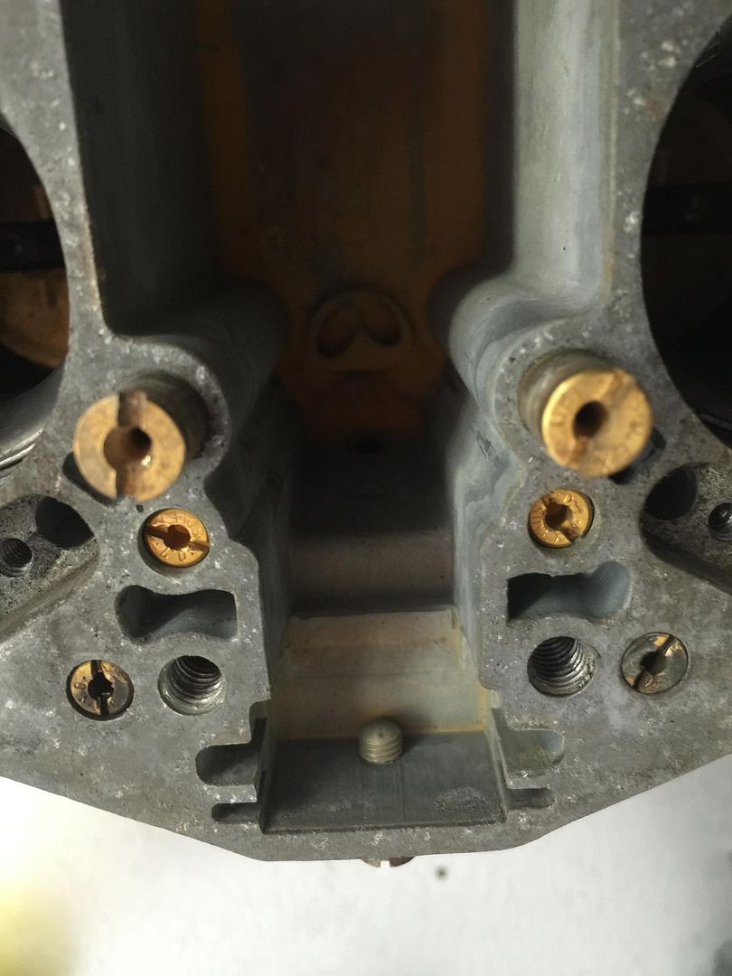
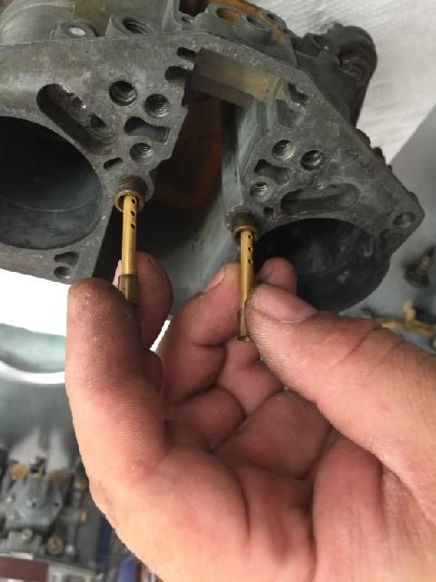
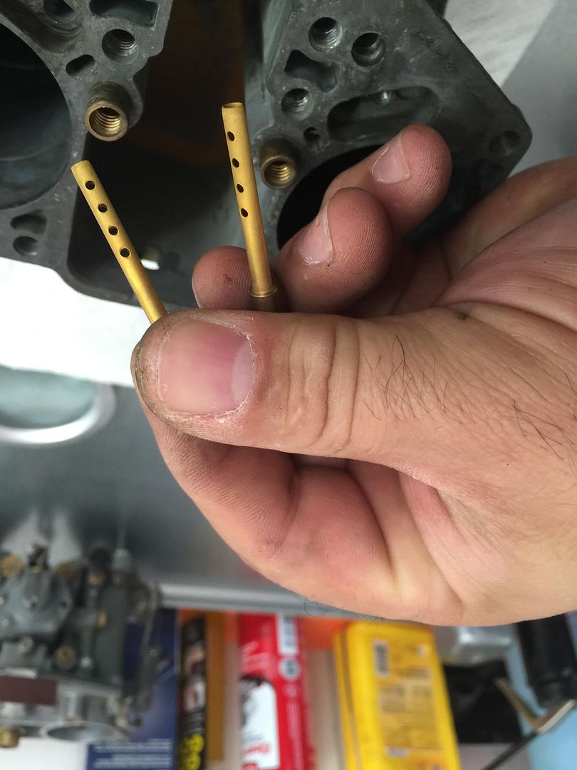
Mental note... documented here on this reply... photo to use as example of where they go...
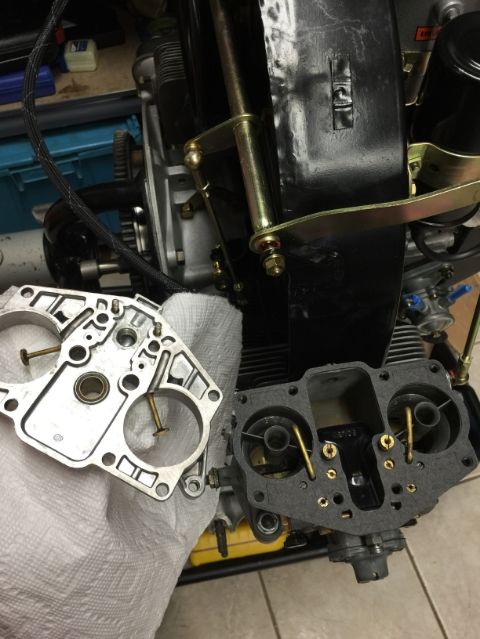
More disassembly
Then carb cleaner again... done...
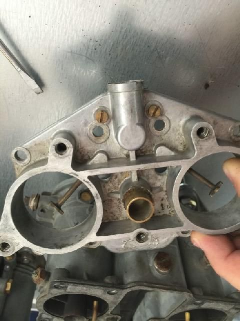
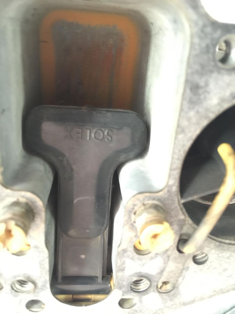
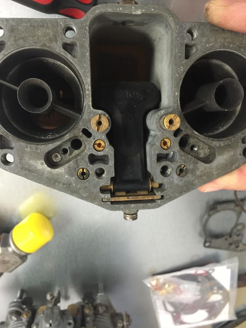
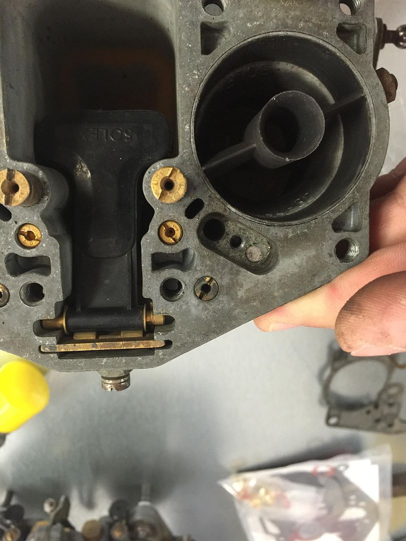
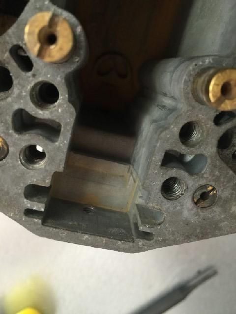
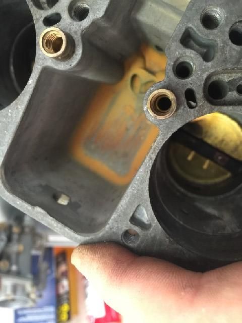
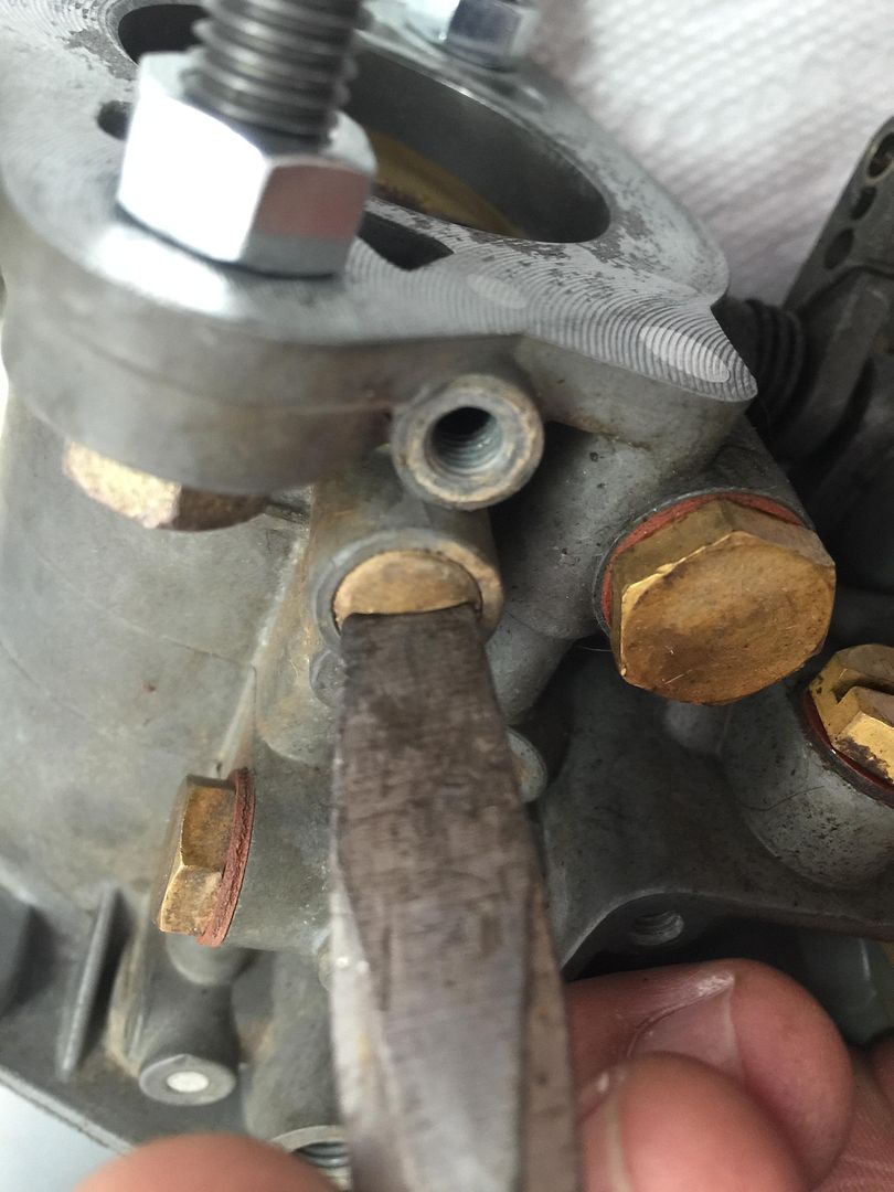
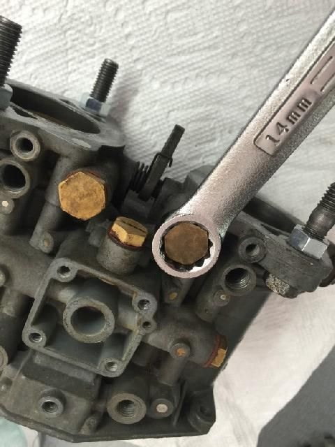
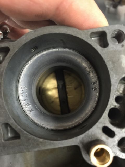
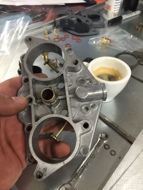
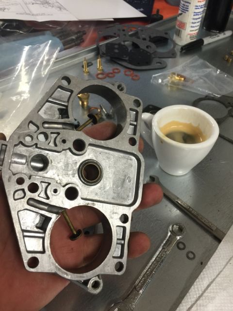
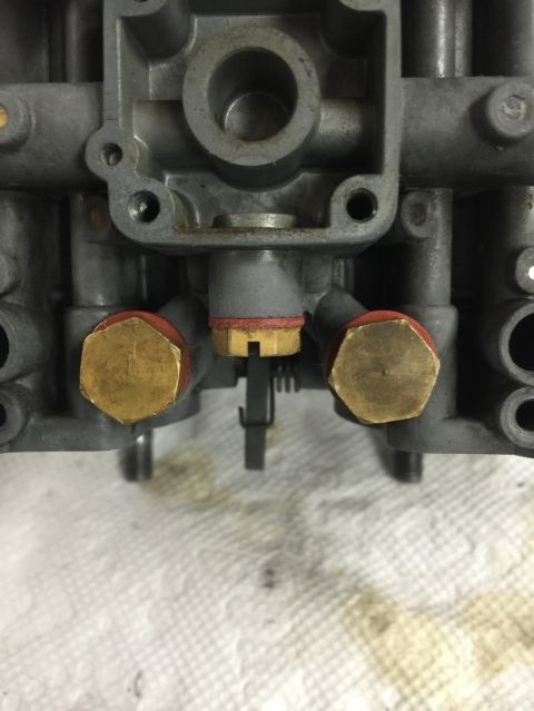
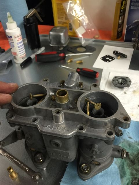
Jaime, those two small jets, which appear to be the same size, on either side of the float chamber, at the gasket parting line, the bright two, below the gasket surface, and the other two, corroded, and flush, farther outboard, can be reversed, and that is not good, make some notes here, and, note the threaded holes for two of the top plate screws, more in line with the two bright ones, with the same threads... oh well, if jets are installed here in error, the top plate screws, will not thread in, due to the blockage.
In Kurt's video, note the alignment of the 022 distributor data plate, and the point plate screw centered above it, and compare to yours. I still suspect, that when yours is static timed, prior to running. the condenser will clear better...
Mike
In Kurt's video, note the alignment of the 022 distributor data plate, and the point plate screw centered above it, and compare to yours. I still suspect, that when yours is static timed, prior to running. the condenser will clear better...
Mike
More disassembly
02-23-2015, 08:07 AM
#414
Professor of Pending Projects
Rennlist Member
Rennlist Member
Thread Starter
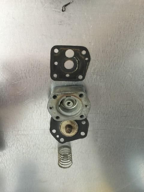
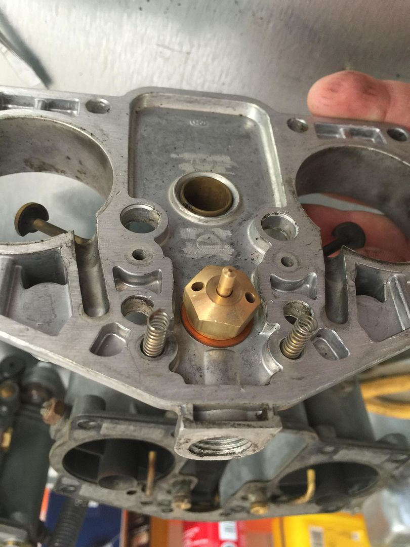
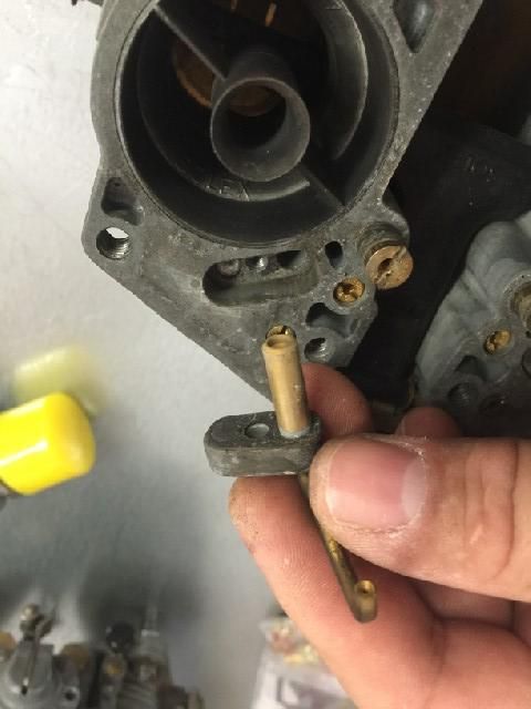
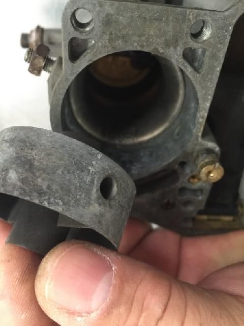
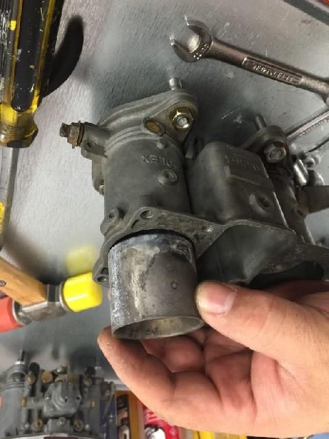
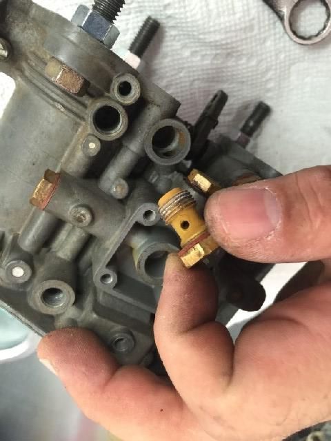
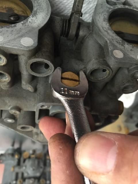
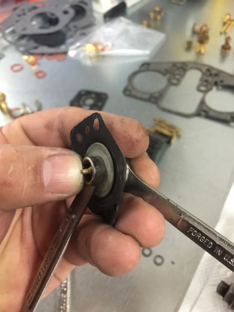
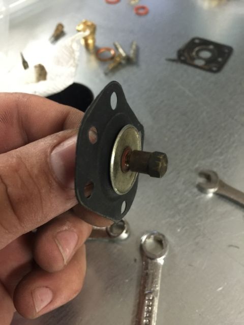
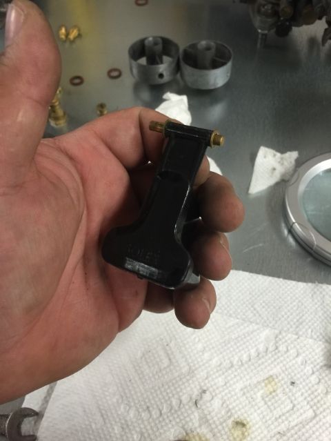
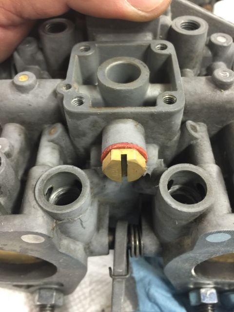
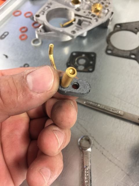
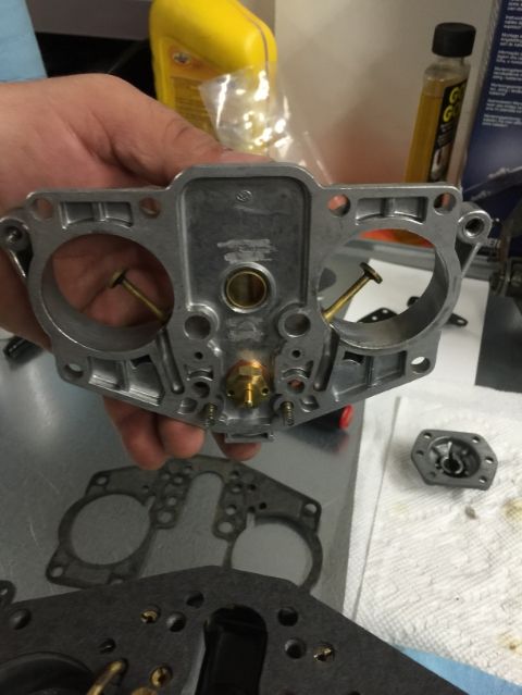
Last part to take apart before starting assembly...
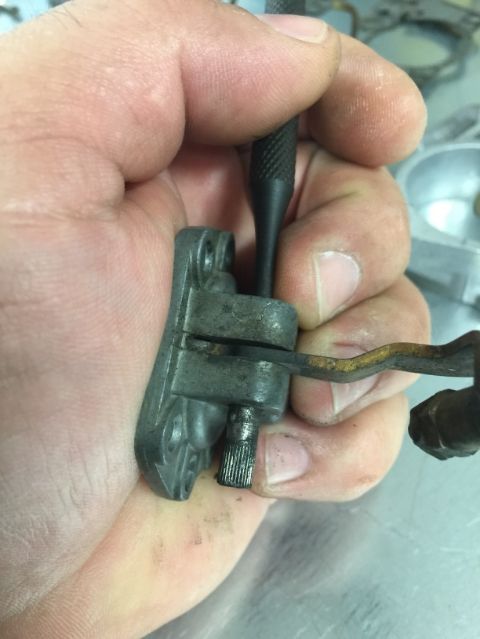
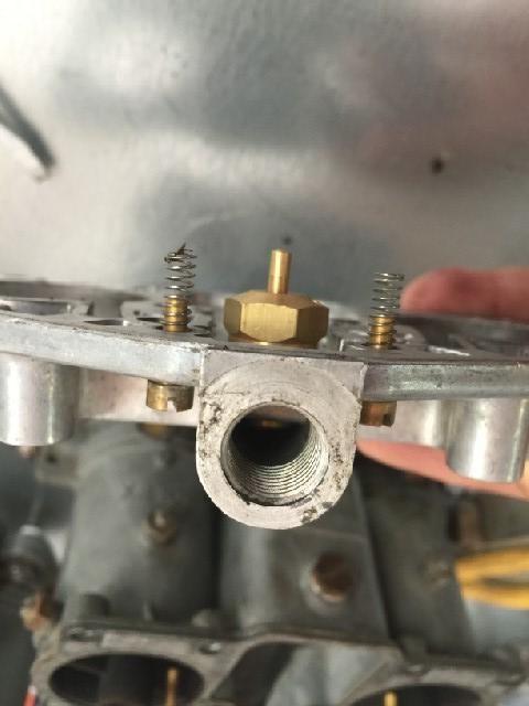
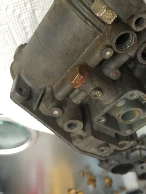
These just slide in back in place. There is an edge that serve as a stop for them...
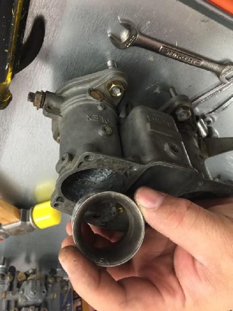
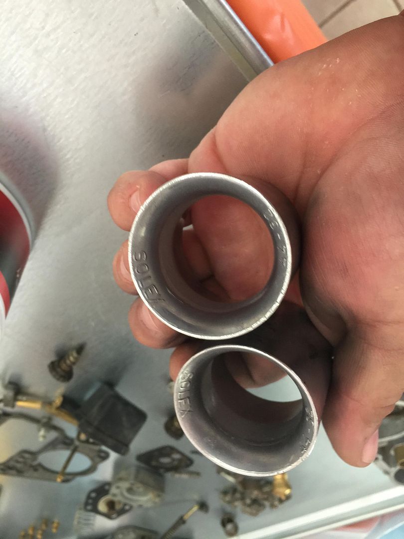
Nice and clean...
Clean as well...
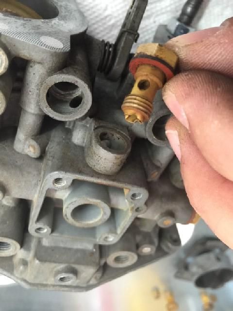
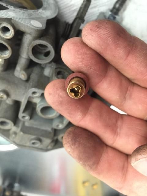
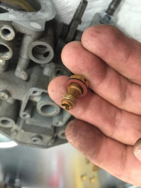
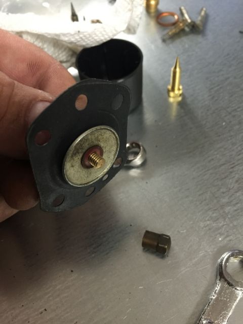
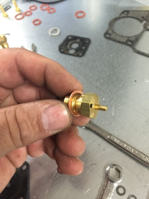
Rebuild kit brings a new valve...
Installing everything back with new gaskets...using the photos of the disassembly as reference for installing everything back...
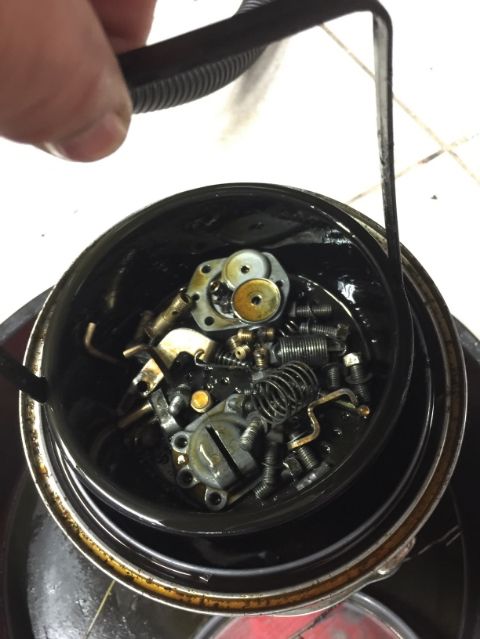
Forgot the photo of the bath of the parts for cleaning... after being the bath for a few hours I then used carb cleaner to blast all the parts and injecting it in all holes to make sure that all the passages were clean and free from any debris...
These just slide in back in place. There is an edge that serve as a stop for them...
Nice and clean...
Clean as well...
Rebuild kit brings a new valve...
Installing everything back with new gaskets...using the photos of the disassembly as reference for installing everything back...
Forgot the photo of the bath of the parts for cleaning... after being the bath for a few hours I then used carb cleaner to blast all the parts and injecting it in all holes to make sure that all the passages were clean and free from any debris...
02-23-2015, 08:09 AM
#415
Professor of Pending Projects
Rennlist Member
Rennlist Member
Thread Starter
more...
Hummm... forgot a photo of the gasket in place... trust me, it is there
Look...
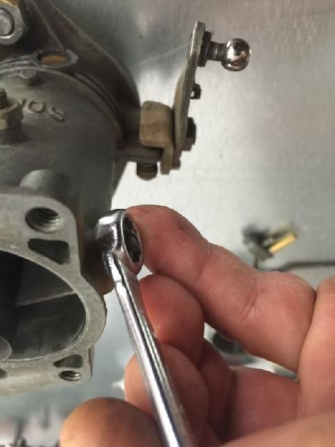
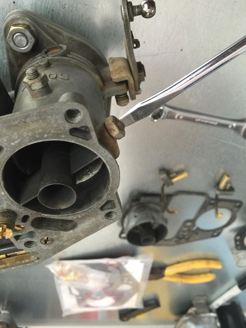
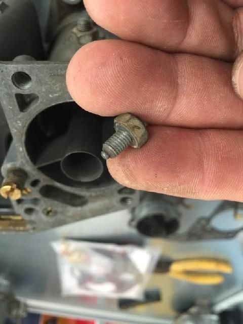
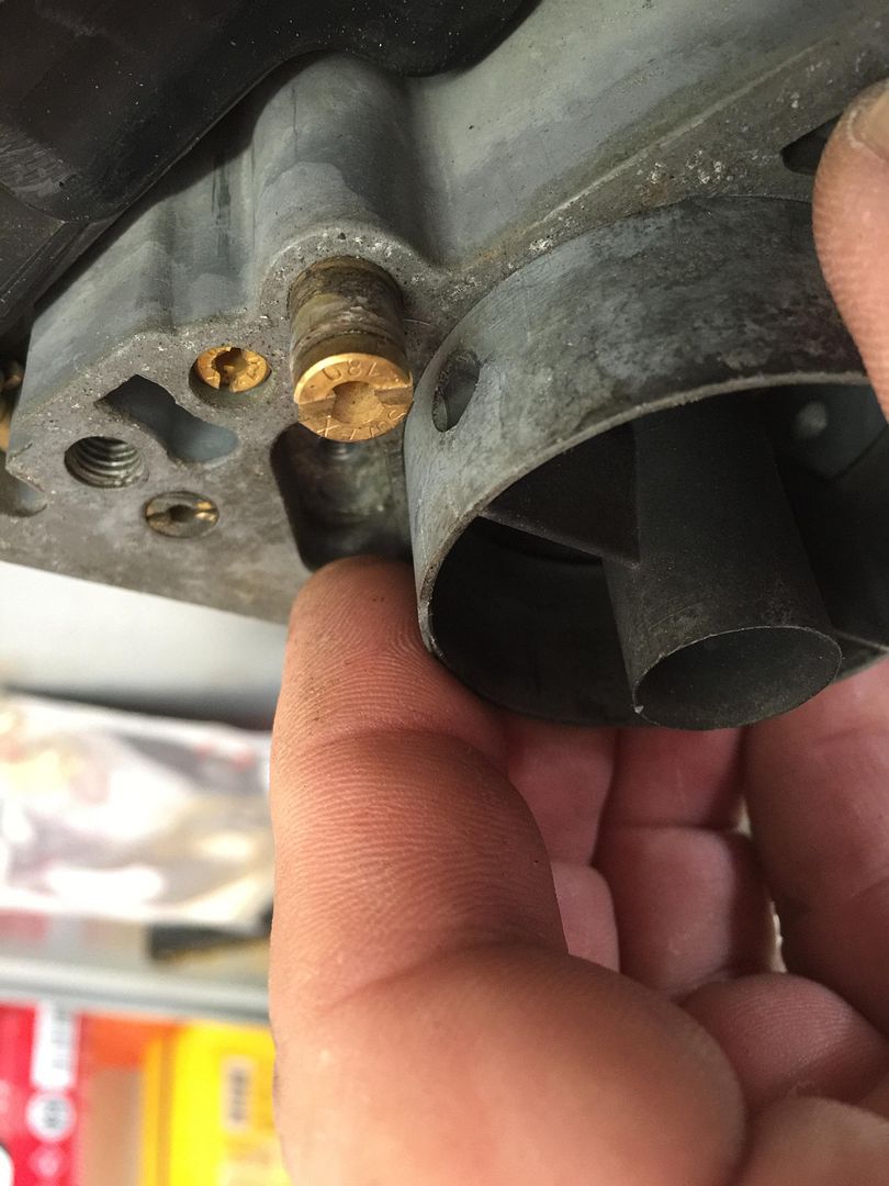
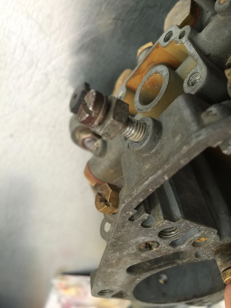
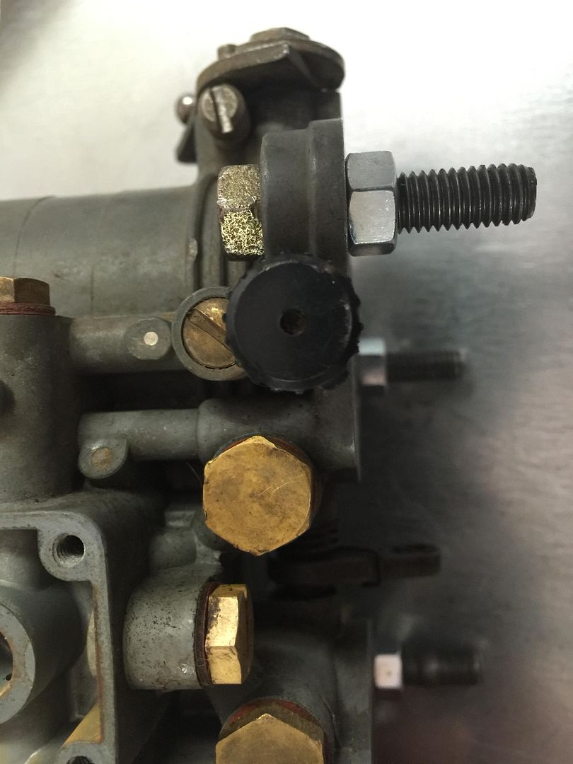
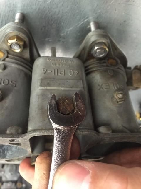
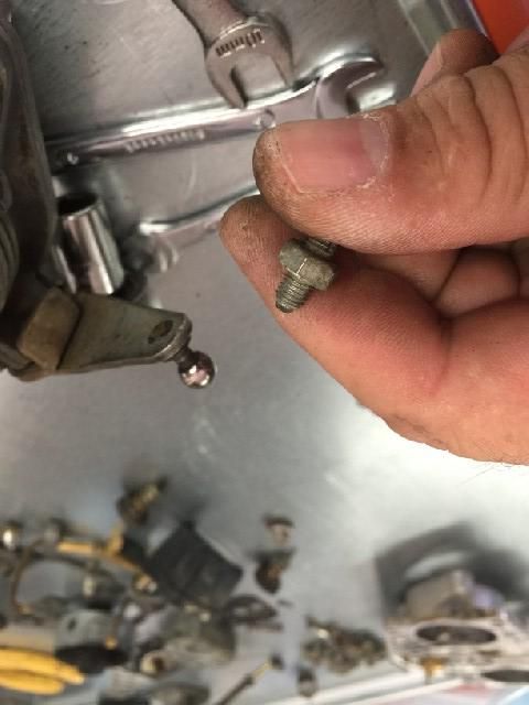
One of the bolts is longer... that is the one used on the spring bracket. Someone forgot to tell the person that worked on this carburetor last time...
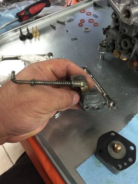
Look at old versus new... still go with the old one Mike?
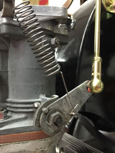
I know that there are probably tests to be done on the bench before installing... but I had to put it on and take photos...
I will start on the next one tomorrow night...
Hummm... forgot a photo of the gasket in place... trust me, it is there
Look...
One of the bolts is longer... that is the one used on the spring bracket. Someone forgot to tell the person that worked on this carburetor last time...
Look at old versus new... still go with the old one Mike?
I know that there are probably tests to be done on the bench before installing... but I had to put it on and take photos...
I will start on the next one tomorrow night...
Last edited by Wachuko; 02-24-2015 at 12:56 AM.
02-23-2015, 08:23 AM
#416
Professor of Pending Projects
Rennlist Member
Rennlist Member
Thread Starter
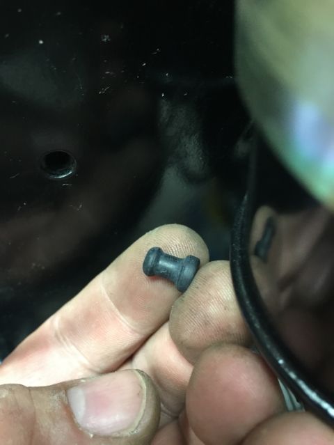
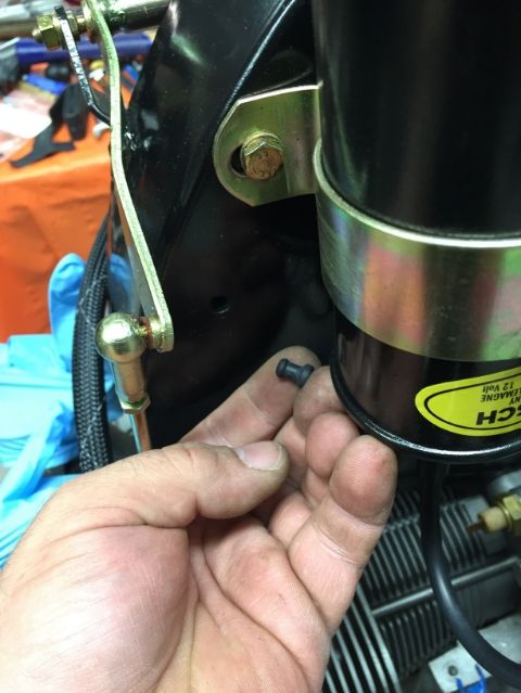
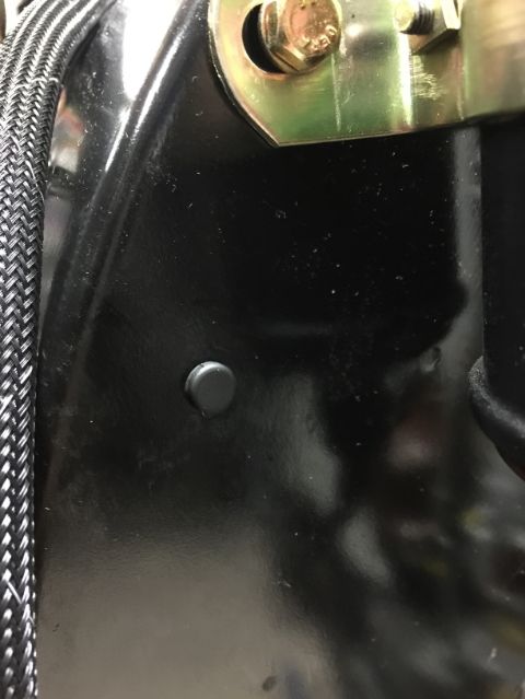
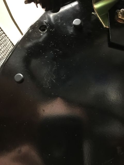
While taking a break from the carburetor, took the time to install these two rubber plugs in the fan housing. One goes behind the coil, so you have to move the coil out of the way... other one is easy to access. Both are located closed to each other. I guess you could just bolt two of the tin metal cover bolts... but since the diagram called for rubber plugs that is what went in...
And glued the gasket to the valve cover. Suggestion made to make it easier to install without the gasket moving around and causing leaks.
And glued the gasket to the valve cover. Suggestion made to make it easier to install without the gasket moving around and causing leaks.
02-23-2015, 06:06 PM
#417
Professor of Pending Projects
Rennlist Member
Rennlist Member
Thread Starter
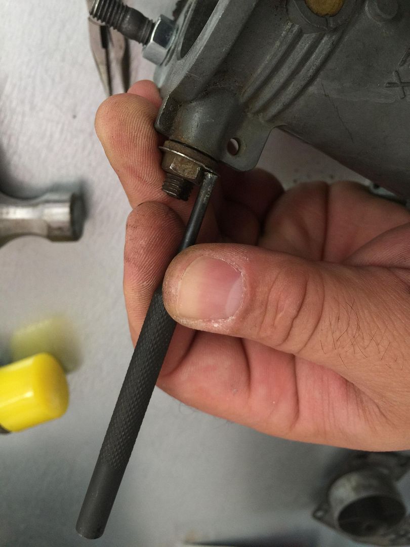
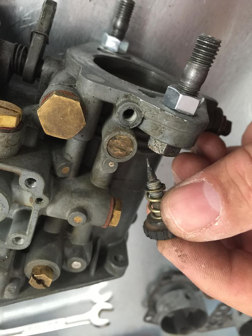
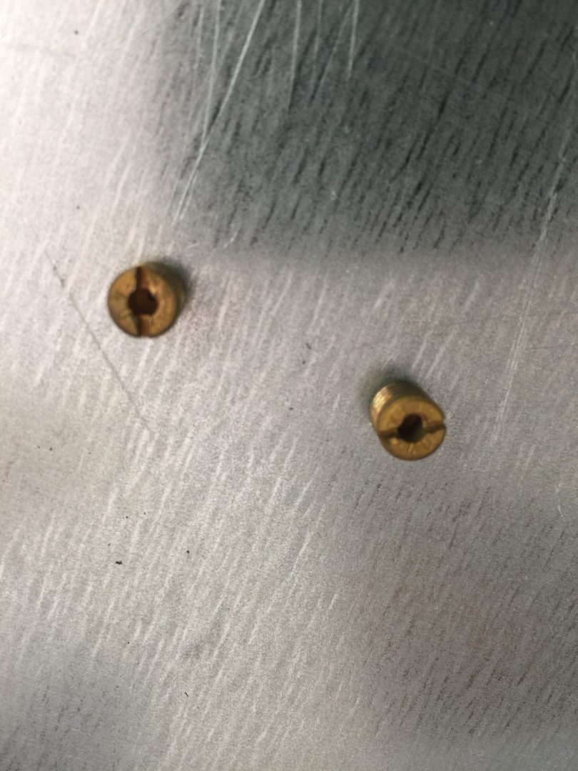
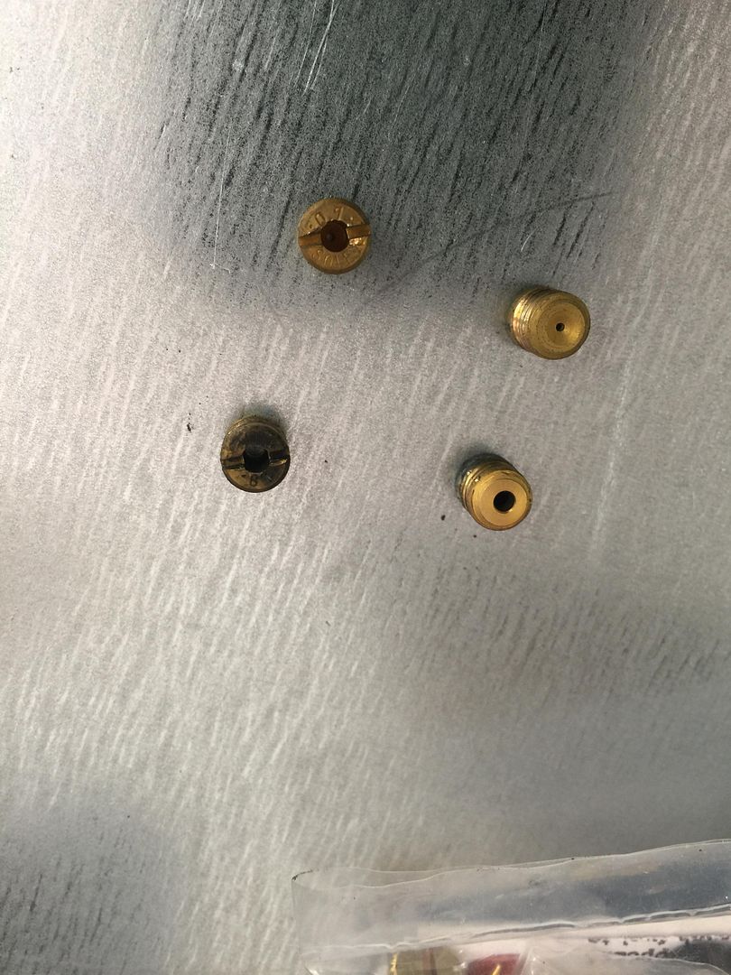
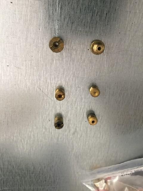
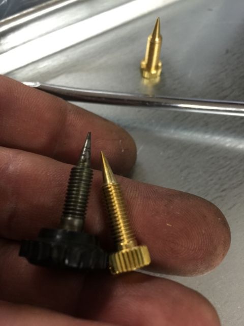
It is recommended by 356 carb rescue to get the 1.75 needle valves with the ball tip. They can supply you with them. Most consider the ones that come with the rebuild kit to be of much lesser quality. The last thing you want is a stuck needle valve on your fresh rebuilt engine. The #1,2 side of the car seems to have more problem than the #3,4 side with a sticking needle valve. I attribute this to the flow in the fuel lines going faster around the outside of the curve in the lines and slower on the inside of the curve of the fuel lines thus carrying more junk to the #1,2 side and causing its' needle valve to stick more often. I have had this happen to me at least 5 times in the past few years. It can cause an engine bay fire since fuel will overflow from the carb down onto the exhaust. It is easy enough to simply install the good ones. I forget how much they cost but it is negligible compared with your investment so far. Bieker rebuilt my carbs and installed the needle valves seen in the far right of my photo. I'd have to look to be sure but they were like 2.25 or 2.00 size which 356 carb rescue told me were incorrect.

Jamie
Jamie
Ordered. I will take that one apart when it gets here... Thank you Jamie!!
So looks like everything is on hold while parts arrive.
Removed and bagged everything until the part arrives...
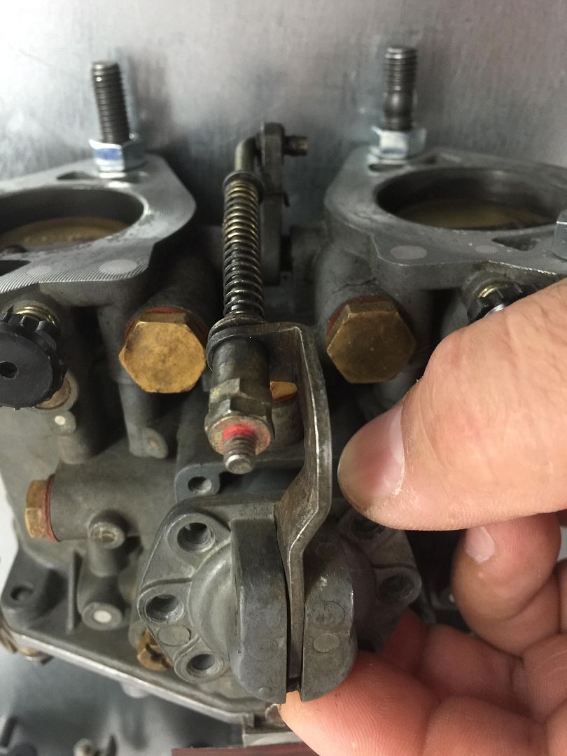
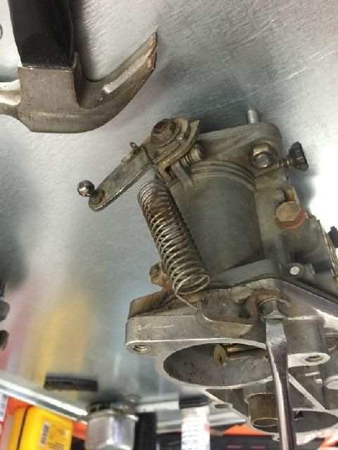
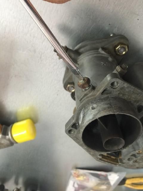
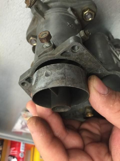
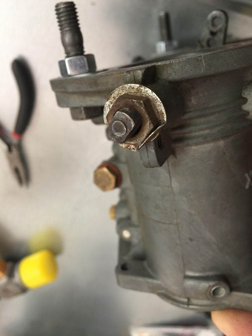
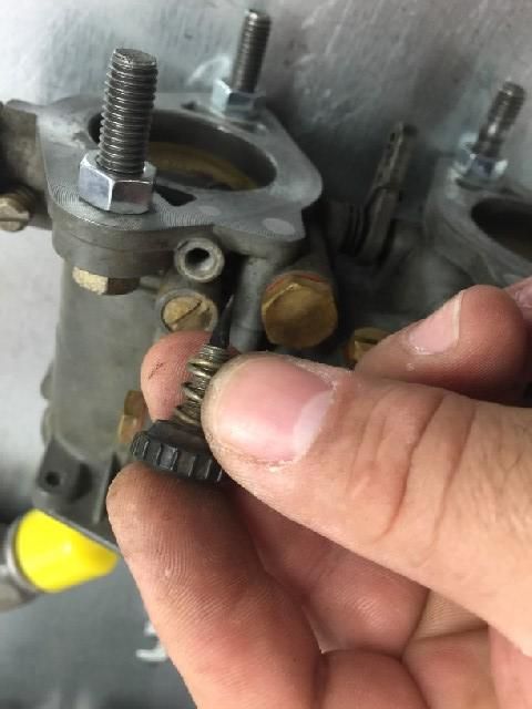
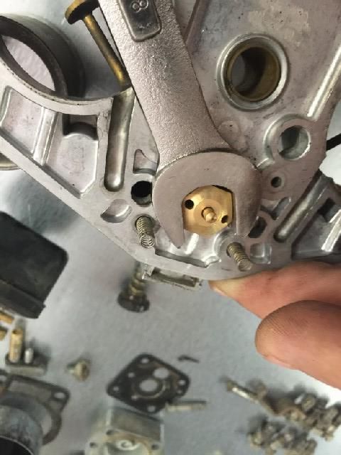
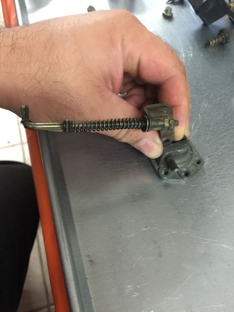
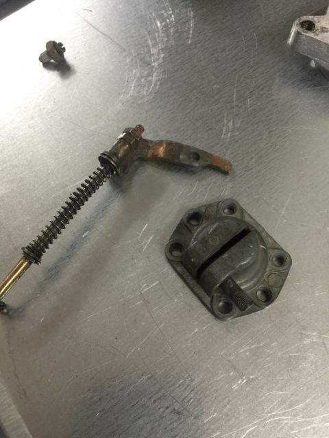
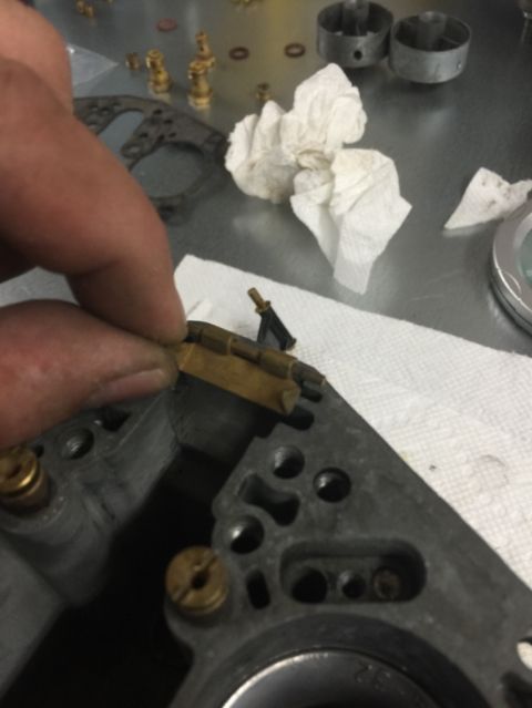
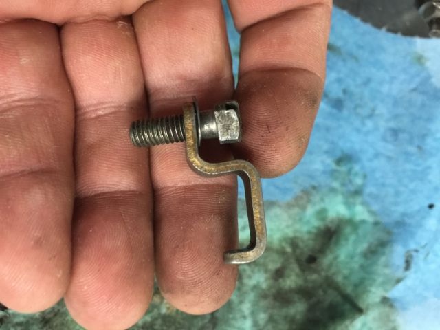
I did noticed this on the tab that holds the spring... with the years of use the spring is eating into the bracket that holds it in place:
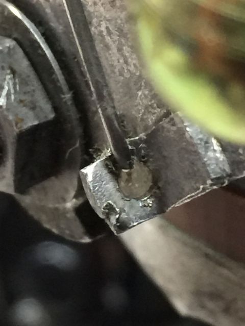
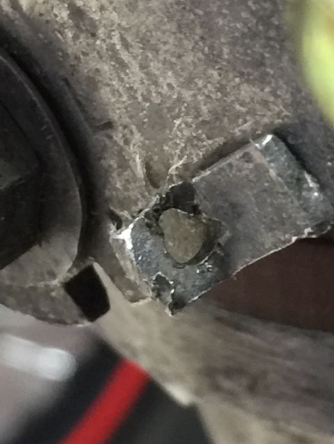
I will figure something out to try to restore that bracket in place... of course, suggestions are welcome
02-23-2015, 09:31 PM
#418
Instructor
I know nothing about rebuilding engines, but how about a galvanized washer or two sandwiched on either side? Could weld or epoxy them on, who knows, it's an idea?
02-24-2015, 12:54 AM
#419
Professor of Pending Projects
Rennlist Member
Rennlist Member
Thread Starter

Then someone suggested a washer... very small one and do what you suggest...
and then someone else suggested the following, which I think is even better and never crossed my mind...
Jammie
Glad you figured out the check valve screen. Also, here is the diagram I was referring to that shows the return flow port for the solid shaft carbs:

The split shaft carbs do not have the same check valve as it has no return flow port, because they moved it to the back of the accel pump chamber.
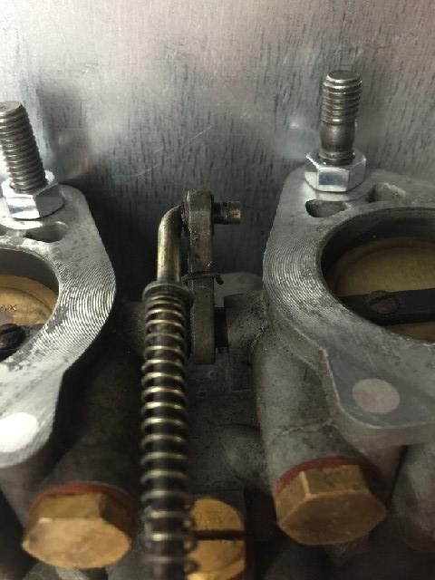
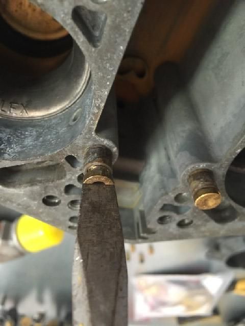
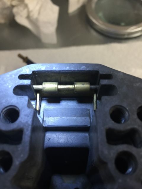
Here is how I fixed my throttle spring tab:

Stick in a piece of copper wire:

Weld around the wire, pull wire out and file down the weld.

Glad you figured out the check valve screen. Also, here is the diagram I was referring to that shows the return flow port for the solid shaft carbs:
The split shaft carbs do not have the same check valve as it has no return flow port, because they moved it to the back of the accel pump chamber.
Here is how I fixed my throttle spring tab:
Stick in a piece of copper wire:
Weld around the wire, pull wire out and file down the weld.
02-24-2015, 12:54 AM
#420
Professor of Pending Projects
Rennlist Member
Rennlist Member
Thread Starter
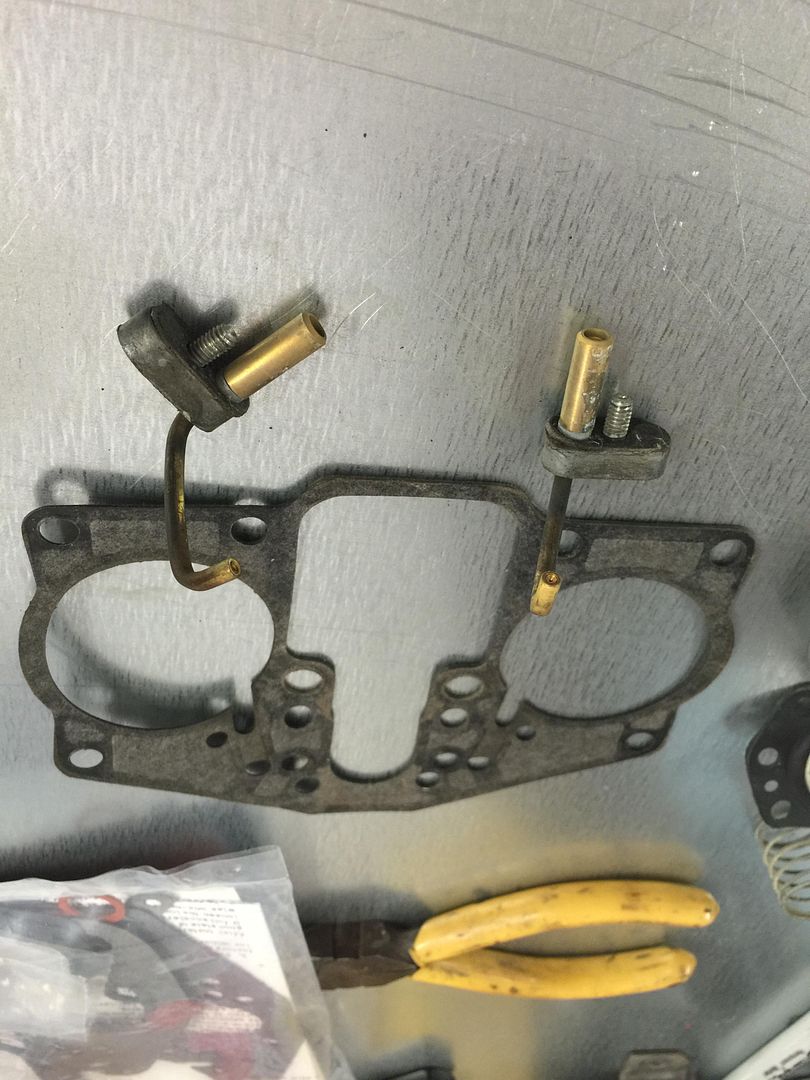
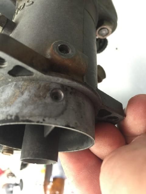
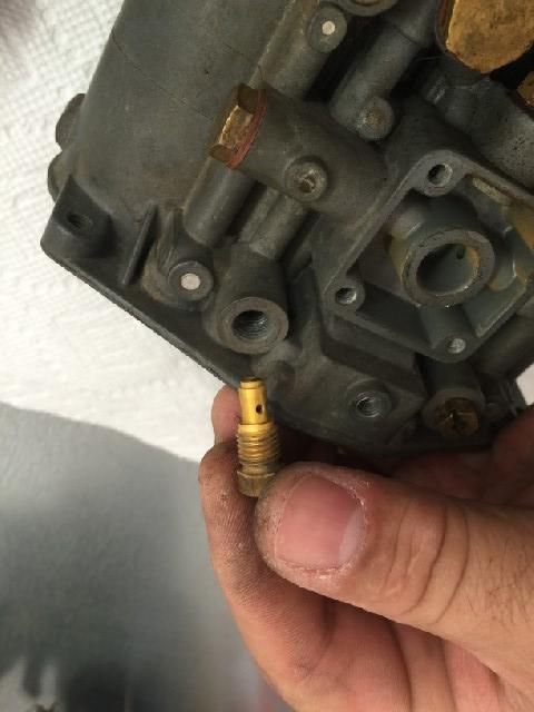
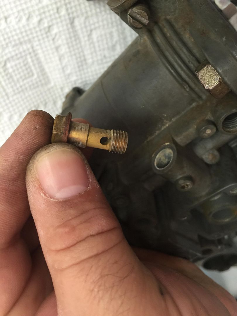
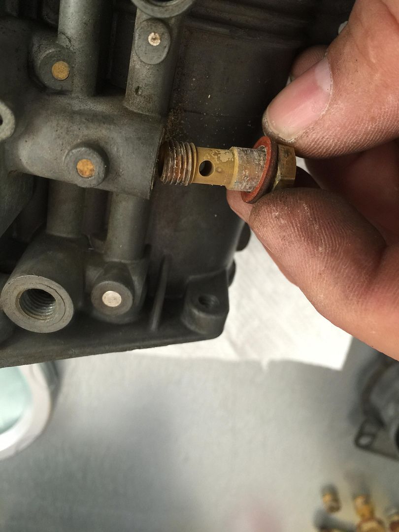
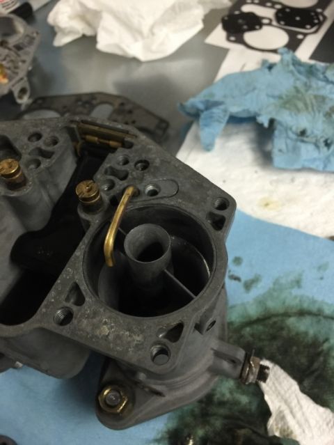
When I took the second carburetor apart... there it was...
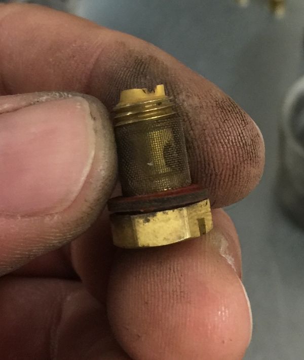
I hope the folks at 356carburetorrescue have them... let me order those...
Jammie
Glad you figured out the check valve screen. Also, here is the diagram I was referring to that shows the return flow port for the solid shaft carbs:
The split shaft carbs do not have the same check valve as it has no return flow port, because they moved it to the back of the accel pump chamber....
Glad you figured out the check valve screen. Also, here is the diagram I was referring to that shows the return flow port for the solid shaft carbs:
The split shaft carbs do not have the same check valve as it has no return flow port, because they moved it to the back of the accel pump chamber....
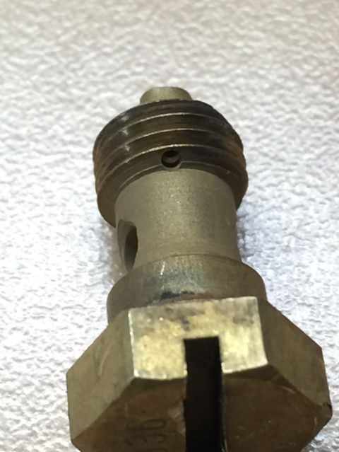
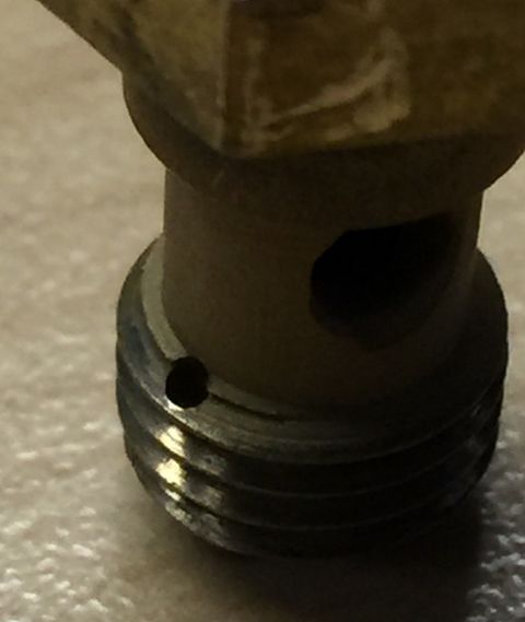
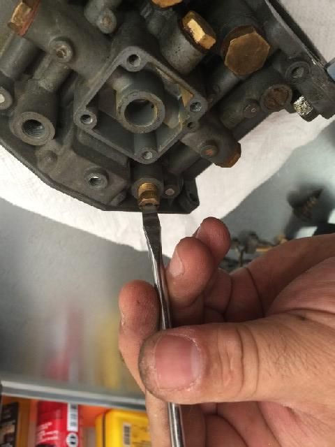
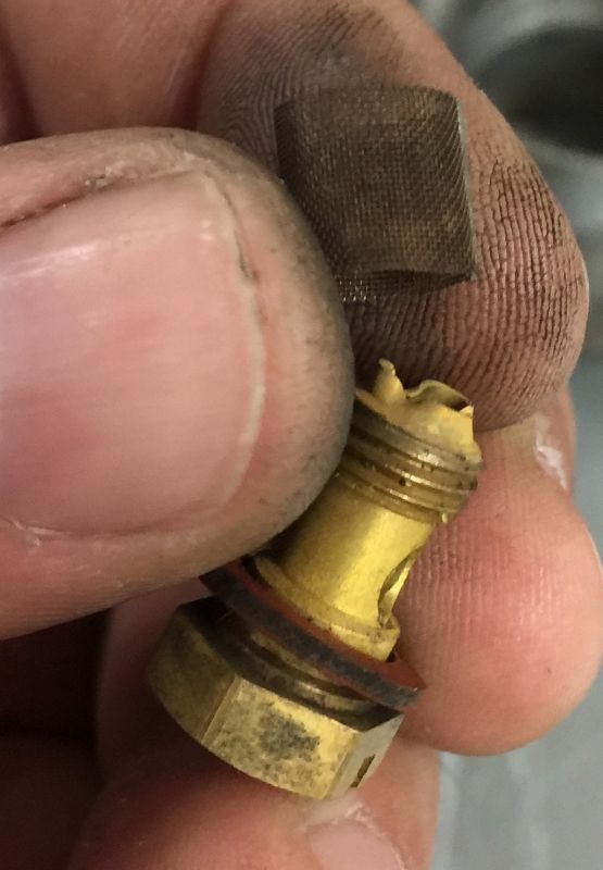
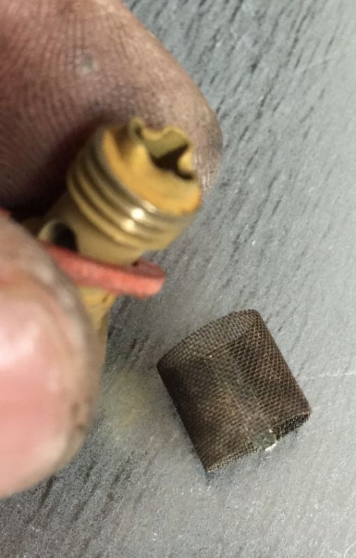
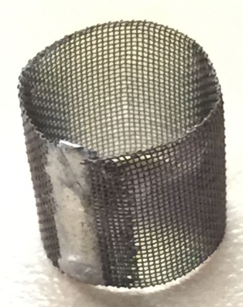
and close up on the screen... Update: the replacement is available, but some assembly required. It is a copper flat sheet that I have to shape and solder to size... I will need to make it look like the one I have in one of the carburetors.
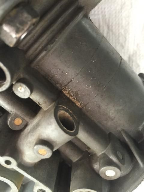
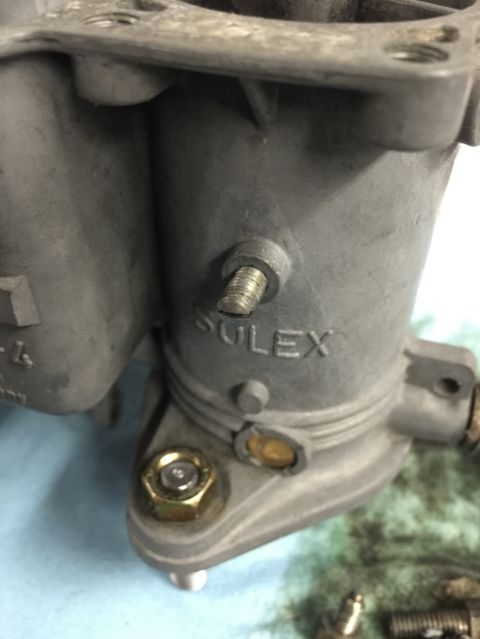
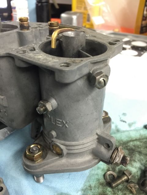
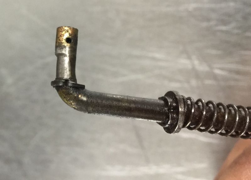
And this part, under closer inspection of the second carburetor, is in need of replacement as well...the one in the other carburetor had some wear... but goodness, not like this one, reason I did not pay too much attention to it... I will order both and replace.
Last edited by Wachuko; 02-24-2015 at 12:32 PM.