When you click on links to various merchants on this site and make a purchase, this can result in this site earning a commission. Affiliate programs and affiliations include, but are not limited to, the eBay Partner Network.
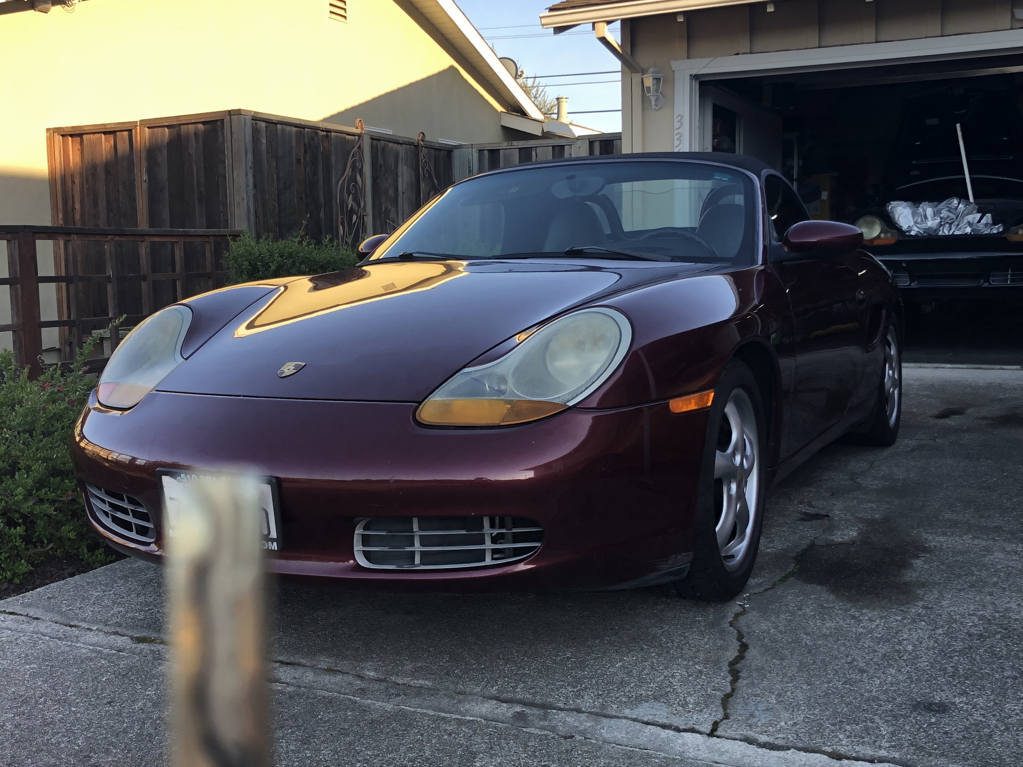
Hey all, been guest-lurking around Rennlist for a while as part of my 986 search. Recently took the plunge on a '99 with 179K miles on the clock. It happened to be the cheapest Boxster I found after looking closely at 2 others, so I definitely violated that golden rule lol.
But the real story is the black 986S shell in the background, currently in the very early stages of an electric swap with a Nissan Leaf motor.
The plan is to prototype the conversion on the cheap (read: very ratty) black shell before swapping it over to the nicer red body with refinements for repeatability. This is a nights-and-weekends project (with three young kids in tow) so I'm giving myself two years to get to that point, which is when the current CA smog on the red will expire Posting here as a record of progress. Comments / suggestions / flaming welcome...
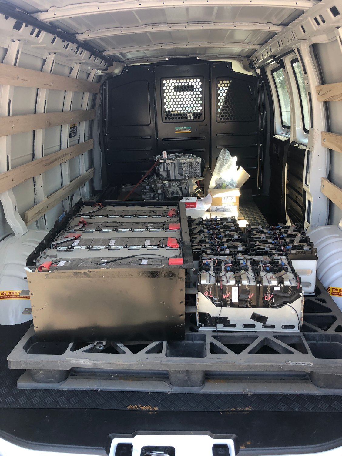
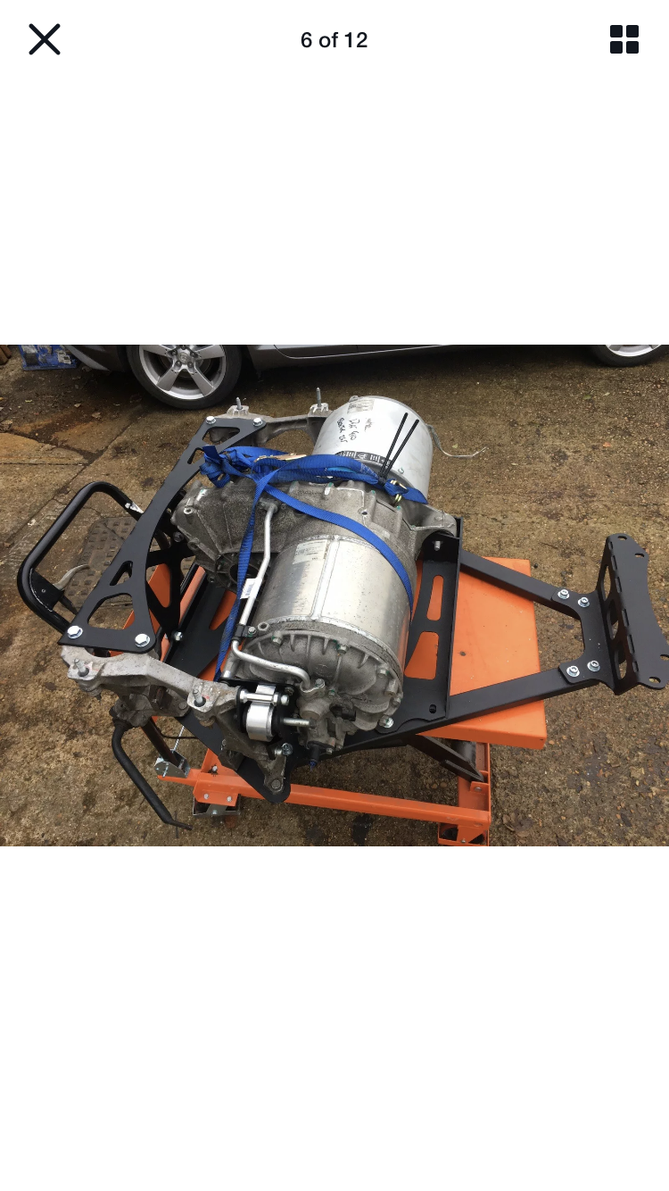
Retroactively posting earlier progress for completeness. This is back in August 2020 when the Leaf motor and BMW batteries (labeled 2009, unknown vehicle of origin, but possibly a Mini E) made it home from Thunderstruck Motors in Santa Rosa:
And my initial bench test of the motor with the Dilithium controller and a scary 300+V of batteries strung together in my garage:
[I should have clarified earlier why my posts are showing up in the Taycan / Mission-E section. I originally posted under "other marques" since this project is going to be essentially a Leaf in Boxster clothing, but the moderators saw fit to move it here. Maybe someday there will be a "DIY Electric" subforum =) ]
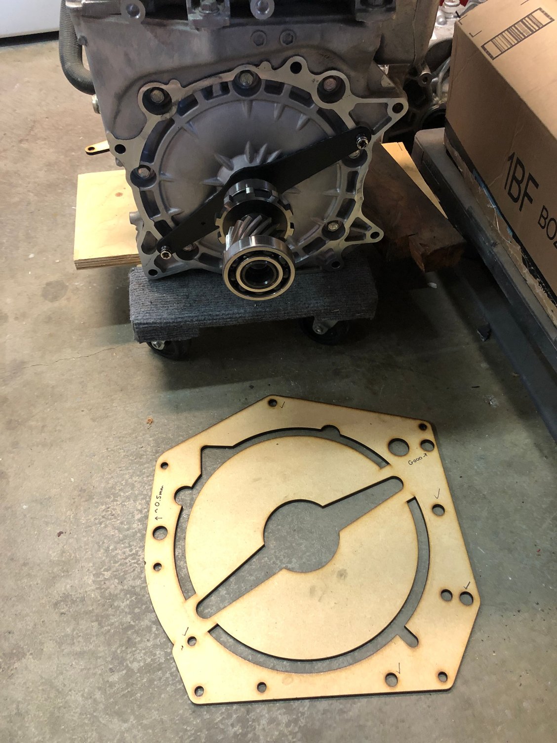
My original plan of attack was to mate the Leaf motor to the Getrag 6-speed, including clutch and flywheel, thinking it would potentially be a more versatile setup - burnouts in 1st gear, freeway driving in 3rd gear.
So I did a lot of work trying to reverse engineer the Leaf motor bolt pattern and the Getrag bolt pattern in order to create an adapter plate. The lasercut MDF template here was one of several test cuts to see if I'd got the bolt pattern right.
I was planning to cut down the Leaf trans input shaft (shown here extracted from the Leaf trans and hanging off the motor) and fashion an adapter to mate with the Boxster flywheel.
Eventually I gave up on this path due to a number of reasons, including:
- The size, depth and weight of the flywheel, and difference in mounting face footprint between motor and trans, would have meant an extremely long cantilever distance from the motor face to the flywheel, which would have been difficult to support in a robust manner
- The adapter plate would have ended up being 2.5" thick
- Even a little bit of shaft runout could have been disastrous for clutch longevity
- I could have done a clutchless setup like many conversions do, but I felt like the compromise in useability (having to wait for rev-matching before shifting) would end up not being worth the complexity of making all the required adapters.
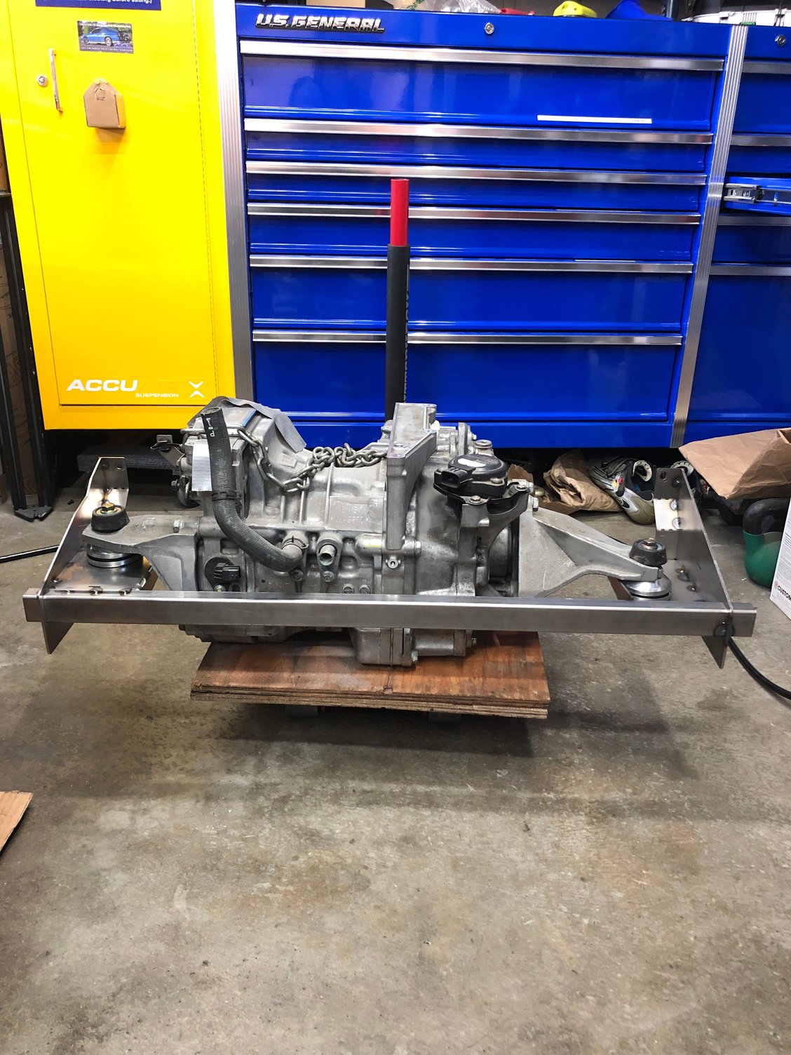
So back to the drawing board, and I revisited mounting the entire Leaf motor and trans and splicing the driveshafts instead - as one would have naturally done for a FWD conversion.
I originally wrote this setup off because the inverter wouldn't have fit, and the OEM bolt-on structural crossbeam would pass right through the motor position.
This time I took off the inverter from the top of the motor, and assumed that I would have to create a substitute for the original structural crossbeam.
With those new assumptions, it looked like this new setup would work. Time to figure out how (and where exactly) to mount the motor.
I am assuming that you have studied the Tesla Roadster for configuration ideas.
TBH I didn't, since I'm using a platform that was never designed to accept an electric motor, and a motor that's physically quite different from the Roadster's. Could you elaborate how that might help?
I did take inspiration from driftmotouk's design for an alternate underbody brace for the Boxster that also serves as a Tesla Model S / 3 motor and battery mount, shown below.
But since the Leaf motor mounts are arranged in a way that's more suitable for FWD applications, my design still ends up being quite different from driftmotouk's.
To be clear, I am referring to the first generation that was based on the Lotus Elise.
I recently met someone who did a 914 conversion. He's been working on it for over 10 years. It is quite driveable, but I'm not sure he'll ever consider it 'finished'.
One thing that was kind of amusing was his heating/defrosting system. He wired a couple of hair dryers in series (matches DC voltage and they apparently run on DC) and mounted them to blow hot air through the windshield vents. No air conditioning/cooling. But in a 914, you just take off the roof panel in the summer time.
Another nice touch was the steering wheel from an old Douglas airliner.
IIRC, his original conversion was with lead-acid batteries. But somewhere along the line converted to LiFePO.
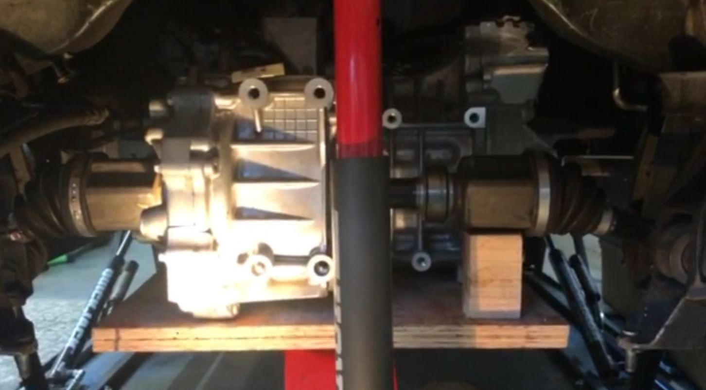
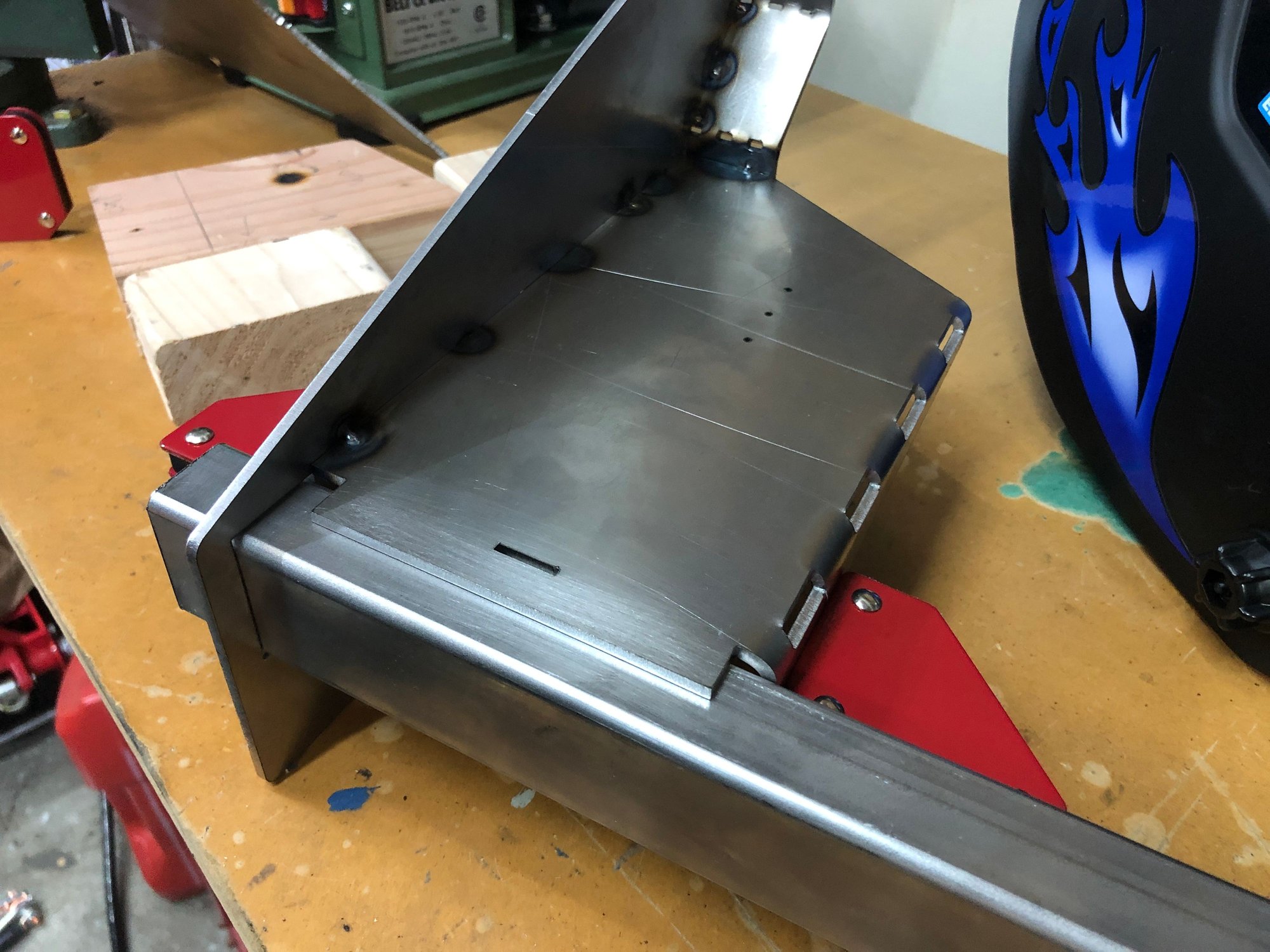
In this post I'll recount how I made the front motor mount(s). The end result (tack welded only, and not yet primed) is shown here as viewed from the front of the vehicle. It's basically two brackets joined by a crossbeam, bolted to the front of the rear subframe, into the same holes that the crossbrace would be bolted to on a regular Boxster.
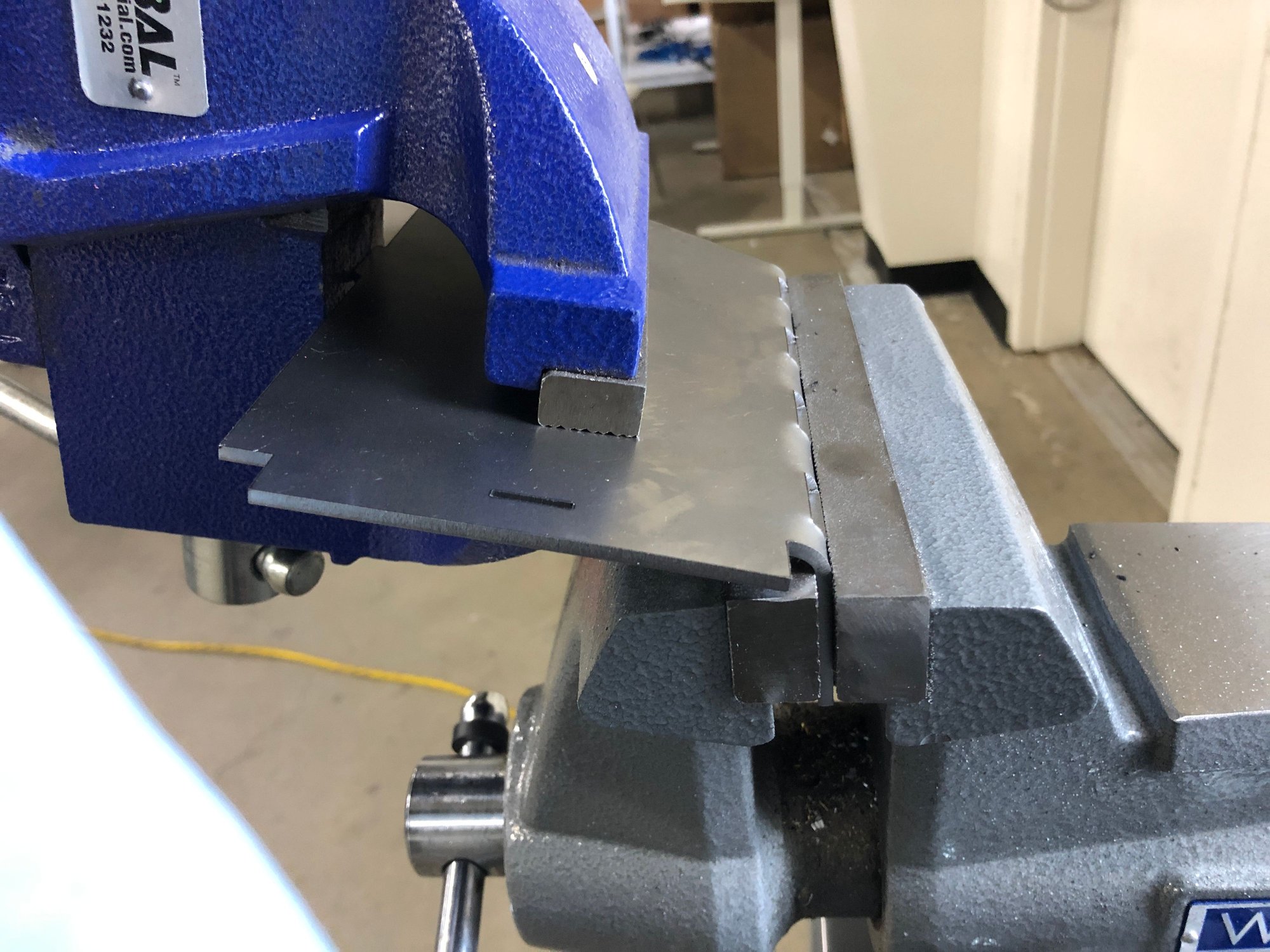
In order to save costs, I designed a welded sheetmetal frame in CAD and broke the design down into flat patterns that I could have sendcutsend.com cut for me. The flat patterns shown below represent the parts going into each of the two (LH/RH) brackets. I had perforated lines where I wanted to fold each piece, and tabs / slots for easy alignment of the pieces.
I don't have a press brake either at home or at work (yet), so I went with the thickest gauge mild steel I could bend by hand using double vises, which was 1/8". This is probably a little too thin for the final final product, for which I'll likely go to 3/16". Easy to mirror image the left and right brackets simply by bending the flat patterns in the opposite direction.
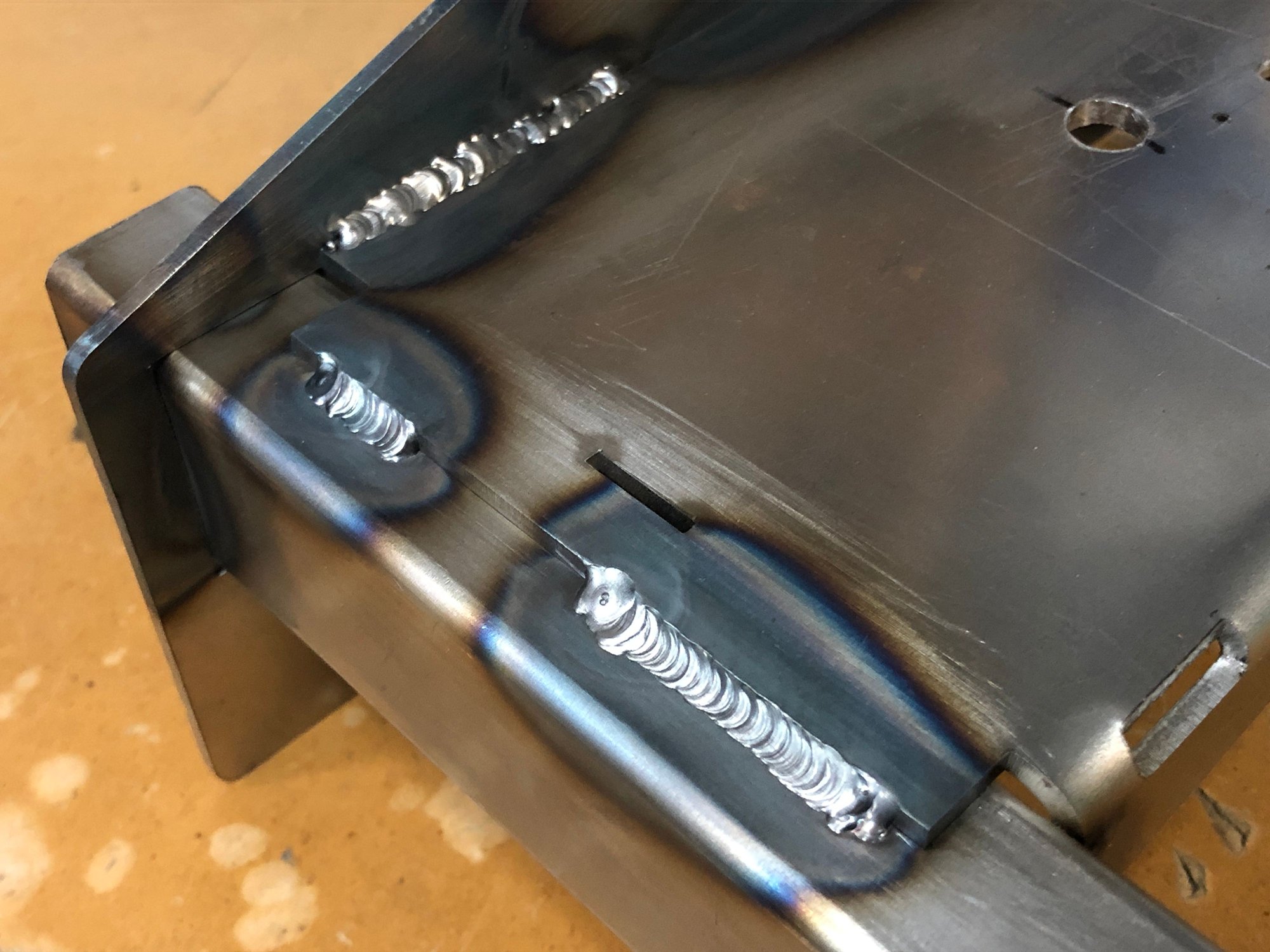
Once the flat patterns were bent and assembled, I could tack weld up each bracket. Picture shows the tack welded RH side bracket with the crossbeam inserted through it for a fit check. The three small holes are trial positions for the front motor mount holes.
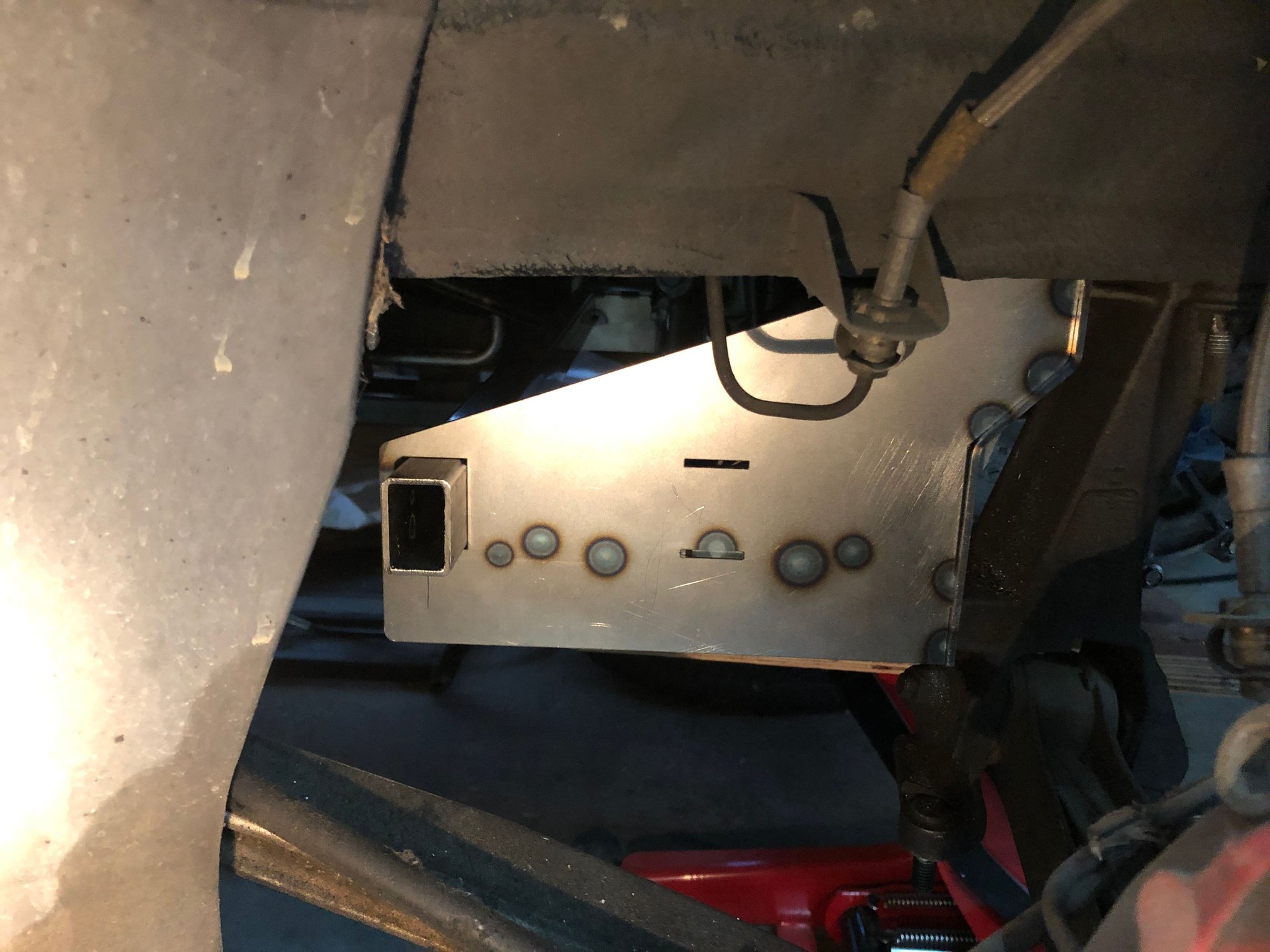
After both brackets were completed, and with the crossbeam loosely inserted through both of them, I installed them onto the subframe in order to essentially use the car itself as a fixture to set the correct distance, before tack welding the crossbeam to the brackets. Picture below shows the LH bracket on the car with the end of the crossbeam sticking through it, just before tack welding.
The last step in constructing the front motor mount was to fully weld up all the joints. In reality the final welding was done after some iteration and confirmation of the motor mount holes, but that process will be covered in the next post.
In all, the lasercut flat patterns and off the shelf tube came up to just $120 in material costs.
In the first pic you see the two vibration isolating mounts with M10 10.9 screws through them at the front of the motor. I'll cover the rear mounts in another post, basically reusing the original Boxster transmission mounts.
In the first pic you see the two vibration isolating mounts with M10 10.9 screws through them at the front of the motor. I'll cover the rear mounts in another post, basically reusing the original Boxster transmission mounts.
Ok so the output shaft is perpendicular to the image?
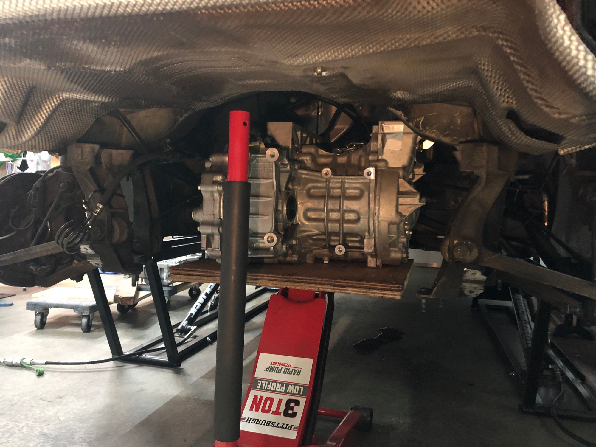
After priming and installing the front motor mounts, the motor was jacked up into place and bolted down at the front. Right hand side mount shown:
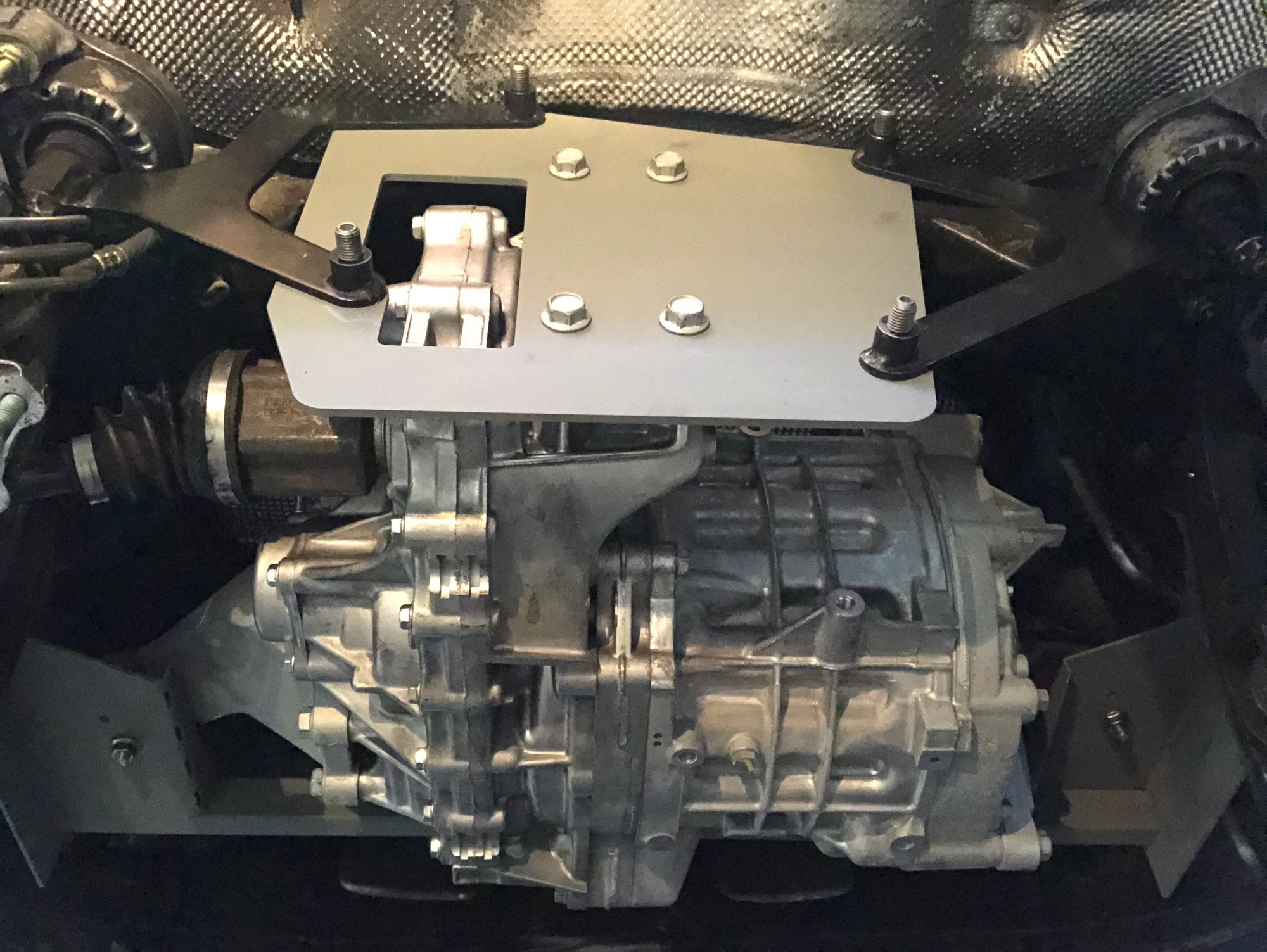
Next, creating the rear mount plate. I decided to reuse the Boxster transmission mounts since they are already damped and end up at just about the right fore-aft position, but I swapped them left-to-right for better clearance with the Leaf motor:
With the mounts in place, I made a multitude of point-to-point measurements and designed an adapter plate:
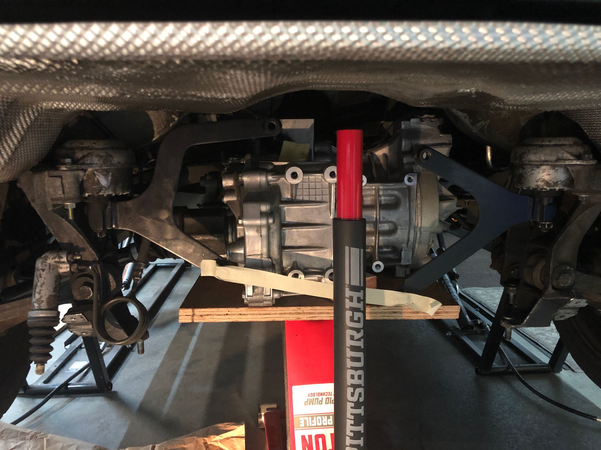
View of all the motor mount points from below, with the motor fully suspended by the mounts.
With the motor mounts finalized, the next step is to look at splicing the half shafts and figuring out how exactly to install them into the motor and the hubs.

 03-10-2021, 04:11 AM