When you click on links to various merchants on this site and make a purchase, this can result in this site earning a commission. Affiliate programs and affiliations include, but are not limited to, the eBay Partner Network.
My ignition switch and/or tumblers are toast (key often doesn't turn or come out etc.). Rather than go through the hassle of replacing the switch with a new one, I figured while everything is apart I could install push button start switch and eliminate the need to use the key. I understand that there is some RFID magic between the key head and the immobilizer, but haven't been able to find much information on how they talk and what would be required to keep that portion working. Does the pill get energized by the induction ring? or vice versa. And in theory, if I key the key secured in some fashion in the vicinity of the induction ring, can I take the main ignition wires and starter wires and connect them to a separate panel. Longacre makes a nice one that I've been pleased with on past cars.
I've been digging for several days but no one seems to have posted anything on this on the interweb. Has anyone tried?
You have correctly described what needs to take place. Disassemble the key to get the pill, attach the pill to the induction ring and tuck up behind dash. Connect switch wires to starting switch. I use a Longacre start switch myself with this setup. Works exceptionally well
Awesome. Do you know what color wires you ran from switch to starter button? Also did you use the long acre on/off switch to turn the cars power on/off? Or did you leave that on the key?
Awesome. Do you know what color wires you ran from switch to starter button? Also did you use the long acre on/off switch to turn the cars power on/off? Or did you leave that on the key?
as to which wires, I will have to go back and look if I have some notes. I remember using the multi meter to finlut where the was a circuit and that lead me to the which ones.
So if I just leave the key in the ignition switch in the off position and intercept the ignition and start wires I can use a flip switch for the ignition and a button for the starter?
I *think* the induction ring still needs to have 12v connected to it, but I was thinking along the same lines of just leaving the key in the ignition so I can take it with me to keep a would be thief from just hopping in and driving away. Still working on how the wiring should run but I am fairly sire
I am pretty sure that at least the following needs to happen (note - NOT wiring genius) Just thinking out loud and probably wrong as I found this on the internet... :-)
- Cut yellow wire (Starter) and splice to one pole of the start button. Then other pole connects to wire going to the starter
- Orange wire Ignition 3 wire to one pole of the power on/off switch. Other pole to battery. Ignition 3 is the ""run" position for the key.
- Red/White is 12v constant - assuming that this would go to the induction ring at a minimum
Not sure how else the rest of the system gets powered
- assume need a 12v source to the headlight switch that would probably be spliced off the Red/White,
- Wipers/DME/Immobilizer. For the DME I am also assuming that these are energized anytime the ignition is on (i.e. when the power switch is)
- need to figure out how the other systems are powered such radio, windows, locks etc. I think they would be powered anytime the switch is on as well? On my 944 when we did this we just ran all of the auxiliary systems directly switched off the power on/off switch. Though the only load on it was the cool suit.
Still thinking through this and am getting some guidance from my wrench. Any thoughts out there?
The whole push button thing seems like a lot of hassle given that a new switch is $10 and takes about a minute to install if you have the assembly already out of the car. Search for 4A0 905 849B on Amazon.
The whole push button thing seems like a lot of hassle given that a new switch is $10 and takes about a minute to install if you have the assembly already out of the car. Search for 4A0 905 849B on Amazon.
Until you have a switch let you down on the dummy grid and don't have the 10 minutes to replace it because they are rolling out on track.Then you realize you drove 1500 miles to that race and now its cost you way more than $10. This was the reason I got rid of the switch for about the same cost as a new $10 switch.
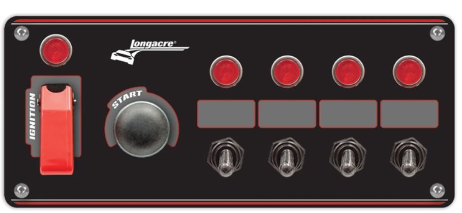
For a race car - it takes a lot of failure points out of the loop and it let's you kill the power with a quick slap of the switch when you are really in a hurry. Also - if you use a panel like this (there's one in carbon fiber - it's faster!) it fits roughly a DIN size area on the center console/radio area and it's prewired/mounted with the switches and lights. Saves a bunch of fab time for various other switched components (cool suit, video camera, data logger etc.)
Ditto mmuller (as we crossed in transit) - was going to also add that the $10 switch failure just cost you a half of your weekend's $2k in race fees, gas hotel.....because you're car wouldn't start.
So I am currently trying to do the same thing by using the switch panel from above. Couldn’t you wire power to the panel and then hook Up the accessory wires, orange wires and the black wire to the ignition switch? Leave the induction ring wires as is. Would Everything work once the ignition wire is flipped on?
OK - got this working today - sorry no pictures as there is zero room and I'd hit my frustration level.
Started the project by removing the "pistol" some weeks ago. I used a grinder to cut off all of the steering lock mechanism - basically the last inch and a half - but left the lug or whatever it's called so I could still use the standard mounting point. the goal was to leave the induction coil powered up so I could put the key in the ignition and allow the DME to start. Basically the tumbler portion is just the "holder" for the key/pill. This way I can remove the key if desired so I have a modicum of anti-theft should I choose to.
I chose the Longacre panel Link to OG Racing with ignition, starter, and two accessory switches. The 4 switch version is shown above, as are the wires in the back.
As a caveat, I highly recommend verifying that you have this wired correctly by using crimp on spade connectors wired to the panel into the electrical switch to be sure this works BEFORE cutting anything permanently.
Next Steps
Disconnected the electrical portion of the ignition switch - shown in #13 above
Igntion: Red/White are 12v. Some are switched, some are constant. You need to find a constant to power the panel. Run the constant 12v to the Brown wire on the panel. This is a 12 or 14 guage wire so if you are using crimp-on it's a blue. No opinion on best method, but gauge is important on some of the others
Starter - Yellow wire. Gets run to the Green wire on the panel. This a 10 gauge or so so will need larger connectors or perhaps a different approach - not an electricion so defer to others on the board
Ignition - this is where it gets interesting. There are 4 ignition wires that need to be connected for this to work. Connecting individually does not seem to work
Black
Black/Yellow
Orange (heavy gauge)
Orange (light Gauge) - this is a 18 gauge or smaller that provides power to the induction ring for the immobilizer. There may be better ways to power this but I just twisted it into the larger orange wire when I spliced
All of these need to get connected to the Yellow wire on the panel
Place key or pill near ring, press starter button and voila!
A couple of other items.
In this configuration, the accessory switches are powered regardless of the position of the ignition. In order the to work, they must be grounded. In the picture above, there are three black wires that come out of the white bulb holders that go up out of the picture. On mine these were pre-spliced with a ring terminal, and just need to be connected to a ground to enable the switches and lights to work.
If you want to run the switches such that the switches will only work if the ignition is on, I THINK that you need to take the Black wire that goes over the top of the started button to the ignition switch, and move it to where the yellow/red attach to the ignition switch. I will try that tomorrow.
Next steps are to pull the radio and HVAC unit and fab up a dash :-)
Theon Goes Full Carbon Fiber With Stunning New Build
Slideshow: Built around a carbon-bodied 964 and a naturally aspirated 4.0-liter flat-six, this bespoke commission highlights how far the restomod formula has evolved.
Tuner Is Converting Porsche 911s Into Shooting Brakes
Slideshow: A Polish Porsche specialist is moving ahead with one of the most unusual 911 conversions in recent memory: a shooting brake version of the 991-generation sports car.
This Coachbuilt Creation Is A Modern Take on the Legendary Porsche 917
Slideshow: A Porsche Carrera GT has been transformed into a one-off coachbuilt machine that blends analog supercar engineering with styling inspired by the legendary 917 race cars.
Is This Convertible Cayenne A Steal, Or A Returnless Investment?
Slideshow: A heavily modified Porsche Cayenne convertible with faux wood trim and a long list of flaws recently sold at auction for surprisingly little money.
Porsche's Top 5 Most Questionable Naming Decisions
Slideshow: For a company obsessed with engineering precision, Porsche has occasionally named its cars in ways that left even loyal enthusiasts scratching their heads.
Pogea Racing's 964 Porsche 911 Reimagination Stands Out in a Crowded Field
Slideshow: Pogea Racing's latest Porsche 964 project blends carbon-fiber construction, modern chassis upgrades, and up to 500 horsepower while keeping the air-cooled 911 experience firmly analog.