PO electrical mods.
#1
Addict
Rennlist Member
Rennlist Member
Thread Starter
Join Date: Jul 2002
Location: Edmonton, Ab
Posts: 2,286
Likes: 0
Received 0 Likes
on
0 Posts
PO electrical mods.
Gotta hate undocumented modifications, especially electrical ones.
In the photo below:
1. What is the plug at the red arrow supposed to connect to? (the AC button it seems)
2. What is the black box at the white arrow? (central locking brain?)
3. What do you suppose the red jumper is accomplishing?
4. What is the big black box at the bottom right of the picture? (HVAC controller -doh)
Last edited by BrianG; 08-13-2017 at 02:20 PM.
#4
Addict
Rennlist Member
Rennlist Member
Thread Starter
Join Date: Jul 2002
Location: Edmonton, Ab
Posts: 2,286
Likes: 0
Received 0 Likes
on
0 Posts
Well, here I thought you guys were good.....
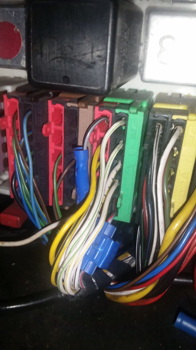
Mostly I am wondering about the fused, red jumper wire. It seems to create a jumper from the AC switch harness to the other (HVAC??) harness and I can't track that within the harness to its destination.
Last edited by BrianG; 08-13-2017 at 02:45 AM.
#5
Rennlist Member
Looks like it's connected to the yellow wire which goes to the internal/external temperature sensors which are connected in series. Not sure why a fuse is required if that is the wire, unless someone has put a resistor in there rather than fix one of the sensors.
#6
Burning Brakes
I share your pain. Just removed an aftermarket alarm and immobilizer. Saw many additional spliced wires to chase.
Why was this done? What did the PO try and achieve?
#7
Nordschleife Master
Since it's all under the console, I'll wager it was all for after-market radio.
Download the wiring diagrams. Once you get the knack for them you'll be able to see what's stock, what's new and what they were trying to do.
Any symptoms?
Download the wiring diagrams. Once you get the knack for them you'll be able to see what's stock, what's new and what they were trying to do.
Any symptoms?
Trending Topics
#8
Electron Wrangler
Lifetime Rennlist
Member
Lifetime Rennlist
Member
1. AC switch (and lamp)
2. Central locking module: 928.618.125.00
3. Not clear *
4. Looks like HVAC (but not in the normally installed location)
* The red wire with fuse - what things work differently with the fuse removed?
Looks like it connects to the Red/white wire on the AC switch loom (correct?) - that would be the Fresh Air Blower relay output. Could be this now feeds the blower separately, or just fuses that line? anyway can you identify the wire colors it connects to at each end, and are they spliced into the circuit or cut and joined?
Alan
#9
Addict
Rennlist Member
Rennlist Member
Thread Starter
Join Date: Jul 2002
Location: Edmonton, Ab
Posts: 2,286
Likes: 0
Received 0 Likes
on
0 Posts
1. AC switch (and lamp)
2. Central locking module: 928.618.125.00
3. Not clear *
4. Looks like HVAC (but not in the normally installed location)
* The red wire with fuse - what things work differently with the fuse removed?
Looks like it connects to the Red/white wire on the AC switch loom (correct?) - that would be the Fresh Air Blower relay output. Could be this now feeds the blower separately, or just fuses that line? anyway can you identify the wire colors it connects to at each end, and are they spliced into the circuit or cut and joined?
Alan
2. Central locking module: 928.618.125.00
3. Not clear *
4. Looks like HVAC (but not in the normally installed location)
* The red wire with fuse - what things work differently with the fuse removed?
Looks like it connects to the Red/white wire on the AC switch loom (correct?) - that would be the Fresh Air Blower relay output. Could be this now feeds the blower separately, or just fuses that line? anyway can you identify the wire colors it connects to at each end, and are they spliced into the circuit or cut and joined?
Alan
The jumper is spliced into one of the green/blue wires from pin 8 in the AC button plug, and into the purple/yellow wire that runs into the HVAC plug. (seen above with the console tipped on its side)
I haven't tested HVAC functions with the jumper removed.
#10
Electron Wrangler
Lifetime Rennlist
Member
Lifetime Rennlist
Member
The Violet/Yellow wire (Purple/Yellow) is the relay output from the HVAC head unit that feeds the Compressor Clutch via the freeze switch and refrigerent pressure switch. Active whenever AC is on
The Green/Blue wire is the output of the manual AC switch and is active whenever the AC switch is on. In the HVAC head unit it causes the AC relay to turn on - however it is not the only reason the AC relay turns on (e.g. DEF mode/Recirc mode/Max AC mode).
It also feeds the Cooling Fan Controller and causes the fans to run when the AC is on (the fan controller also has a freon pressure switch to control the fan rate).
Seems this will ensure the fan controller comes on under more conditions (before the refrig pressure switch requires it). It's really a quite small change - not sure why anyone would have done it. GTS cars behave more like this anyway...?
So generally its likely to modulate the cooling fan speed.
Alan
#11
Addict
Rennlist Member
Rennlist Member
Thread Starter
Join Date: Jul 2002
Location: Edmonton, Ab
Posts: 2,286
Likes: 0
Received 0 Likes
on
0 Posts
Thanks a ton for the information Allan.
I'll be more comfortable removing that jumper now. I am not using the OEM rad fan system at all.
I have replaced the OEM fan setup with one similar to the one Hans built, in consideration of the Andy Keel blower I am running. I have built a stand-alone fan control circuit utilizing a temp switch in the rad with one relay from that switch, and one relay from the A/C clutch feed.
#12
Addict
Rennlist Member
Rennlist Member
Thread Starter
Join Date: Jul 2002
Location: Edmonton, Ab
Posts: 2,286
Likes: 0
Received 0 Likes
on
0 Posts
Other wires
While I have your attention....
There is this other wire...
I suspect it is from the oem cigarette lighter.
The brown pair appear to be (-).gnd.
The black with yellow trace, switched 12+
The thin, solid black - No idea. Might it be dimmer + side? I'd sure like to find one of those for my boost gauge backlighting.
#13
Electron Wrangler
Lifetime Rennlist
Member
Lifetime Rennlist
Member
While I have your attention....
There is this other wire...
I suspect it is from the oem cigarette lighter.
The brown pair appear to be (-).gnd.
The black with yellow trace, switched 12+
The thin, solid black - No idea. Might it be dimmer + side? I'd sure like to find one of those for my boost gauge backlighting.
Alan
#14
Addict
Rennlist Member
Rennlist Member
Thread Starter
Join Date: Jul 2002
Location: Edmonton, Ab
Posts: 2,286
Likes: 0
Received 0 Likes
on
0 Posts
It IS for the cigar lighter. The "Black" wire should actually be Black/Blue (check). The Black/Blue is non-variable illumination (on with marker lights (always) - goes to the supply to the dimmer). You can certainly use it for gauge illumination. Black/yellow is X-Bus (Accessory) for the cigar lighter.
Alan
Alan
Last edited by BrianG; 08-13-2017 at 09:03 PM.
#15
Addict
Rennlist Member
Rennlist Member
Thread Starter
Join Date: Jul 2002
Location: Edmonton, Ab
Posts: 2,286
Likes: 0
Received 0 Likes
on
0 Posts
I should have known better than to poke this hornet's nest!
One more conundrum.
This splicer appears to connect the grey/black wire from the top of the red plug, to the grey/red wire at the bottom of the adjacent green plug.
The grey/black wire also provides a tap that isn't being used.
I note that the tap used to provide power when the lights were on.(before I removed the splice)
Now, with the splice removed, there is:
1. No power (at that tap) at any headlight position.
2. No running lights (tail lights or side markers)
3. No brake lights
All front light functions are normal.
License plate lights are functional
Signal lights are functional
Ideas about:
1. What that splice was for?
2. How to properly fix the running lights?
NOTE: This is a ROW car.
Last edited by BrianG; 08-13-2017 at 08:59 PM.