When you click on links to various merchants on this site and make a purchase, this can result in this site earning a commission. Affiliate programs and affiliations include, but are not limited to, the eBay Partner Network.
Alan, where can I pick up a variable lighting tap in this area of the harness? I'd sure like it for the guage backlighting as these guages I have are very bright in the black interior, at night.
The clock has a variable illumination supply on the Black/Blue wire.
I believe the the plug you are referring to in both cases is the green plug "O". It is best known as Plug O since there are multiple green plugs. It has 2 halves left & right. The terminals on the left side are O11 (bottom) -> O15 (top). The terminals on the rights side are O21 (bottom) to-> O25 (top). So your connections of interest are O15 & O21.
These are the outputs of the fuses for the marker lights (#40) left & (#41) right. I don't know why they connected them together there is no good reason - so evidently they didn't know what they were doing - just take these apart and leave them apart.
You need to reconnect the wires that were there before - same colors.
Alan
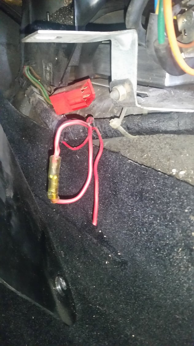
These 2 wires were just joined by the splicer, not parted/cut. I removed the splicer, leaving those two wires now separated but intact.
Now no running lights or brake lights. They were functional before I removed the splicer.
One more identification if you would. I am sure hoping it's the last!
They took the splice to a nearby grounding point. I wonder where it was going to? There is no continuity to ground on the cut wire.
This is the timing belt tensioner switch. They bypassed the tension sensor - you now have no indication of a loose timing belt. Do you have a porkensioner fitted in place of the stock tensioner? if not this is a very bad idea... if your timing belt breaks or slips you will destroy at least the valves - possibly much worse $$$$.
You really do need to get the wiring diagrams and learn how to read them. Without them you cannot realistically maintain the car.
Get the diagrams:- best to get the Jim Moorehouse set from Roger @ 928srus
The connector looks to be oem. The trace on one of the spliced wires is black. The other two have no trace.
What's going on here?
What of the cut wire?
This is the connector for a window switch or sunroof switch. If you tell me the all the colors I can tell you which it is. But you probably already know based on what doesn't work (or if you have no sunroof).
I don't know for sure what the red black wire (etc) is, my best guess is that is is for the suppressor (inductor) for the Audio head unit. It has therefore been bypassed (maybe removed). This was a bad idea - it is actually an excellent high value inductor - it looks like a small transformer - but with only 3 connections. Should be on drivers side in the console near the ashtray area - look. There may be a ground (brown) wire attached to it or floating about there - that is the 3rd connection.
Seems you had a PO with some rather poor ideas (or no idea at all) - a cause for some general concern I think.
Thanks for all the wiring assistance. With your help I think that all of the current electron issues have been resolved.
The HVAC jumper is removed. The new fans run on a separate new circuit, complete with a separate a/c trigger.
The running light jumper is removed and the lights work properly.
The lighter circuit's Black/Blue non-variable illumination lead now triggers the auto-dim feature in the new radio head unit.
The dimmed clock backlight circuit now also provides dimming backlight to the boost gauge.
The persistent "Belt Tension" warning light is extinguished as desired with the PorKen tensioner.
I have a full set of 928 manuals but find circuit reading a challenge to match with chassis harness location. I have contacted Allen, with much hope, about his "928 electrics" project.


 08-13-2017, 08:56 PM