When you click on links to various merchants on this site and make a purchase, this can result in this site earning a commission. Affiliate programs and affiliations include, but are not limited to, the eBay Partner Network.
My only thought is, if the harness is this bad, even if you rig it up to verify that it runs, the chance of it flaking out on you and causing all manner of weird behavior down the road is pretty high. By all means, do this to verify that it's the problem, but for peace of mind, a replacement harness is not a terrible idea.
Hi, thanks for the note. I agree, just trying to make sure I have a decent running to work with before diving into everything as part of a rolling restoration.
My intention is to use her for fast road touring events, as a GT in other words, so making sure she is reliable is pretty important. I am recently back from a Canadian boarder back to SoCal run on secondary roads and believe me I don't want her getting flaky on that sort of trip.
Makes sense, I just want to clarify some 928 terms in case you order a new harness. People usually call the harness that runs through the 14-pin connector the engine harness. You're having trouble with your injection harness.
Of course they're NLA from Porsche either way, but some of our vendors make replacements (but not as certain about '84)
Thanks, "ignition harness" is how I will refer to it going forward. I'm expecting to find other issues once I get past this one. Hopefully this will do it but I'll probably see if 928 Intl has a good no-excuses one for me soon.
Have you done a continuity check with a multimeter on the 4 ground wires in post #83? The ones that you have disconnected and fount that 2 were broken?
If these go to pins 5, 16, 17 and 35 of the L Jet connector, that may be your problem. You will be able to check the individual wires now that they are separated.
Does the 84 wiring diagram show 4 wires going from those pins to a common ground point?
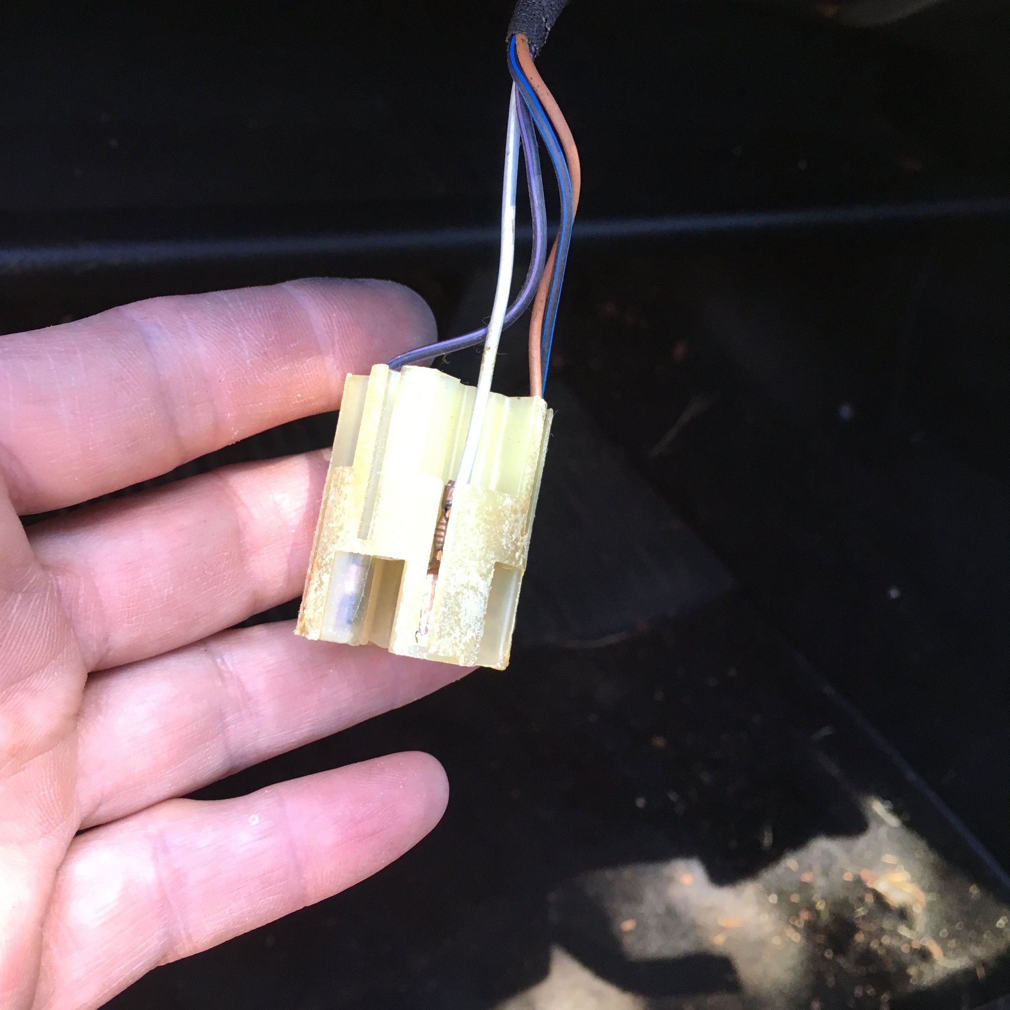
It appears from your photo that there were originally more than 2 wires at the ground point (the 'ring' connection that you have cut off)
Good morning (or early afternoon).
All four of these wires were at the same ground point via single ring connector near the O on the passenger side cam cover.
I have NOT been able to find any of the other grounds that Nate referenced in post #80, so it is possible that someone else has been in here and relocated what used to be separate grounds into a single connector.
I tested the two that I stripped back, both are dead. They were joined together pretty well so it is likely that all four are toast.
I have traced all four back into what I believe to be the Injector Harness, so these should be the ones that end up in 5, 16, 17 and 35 for the L-Jet.
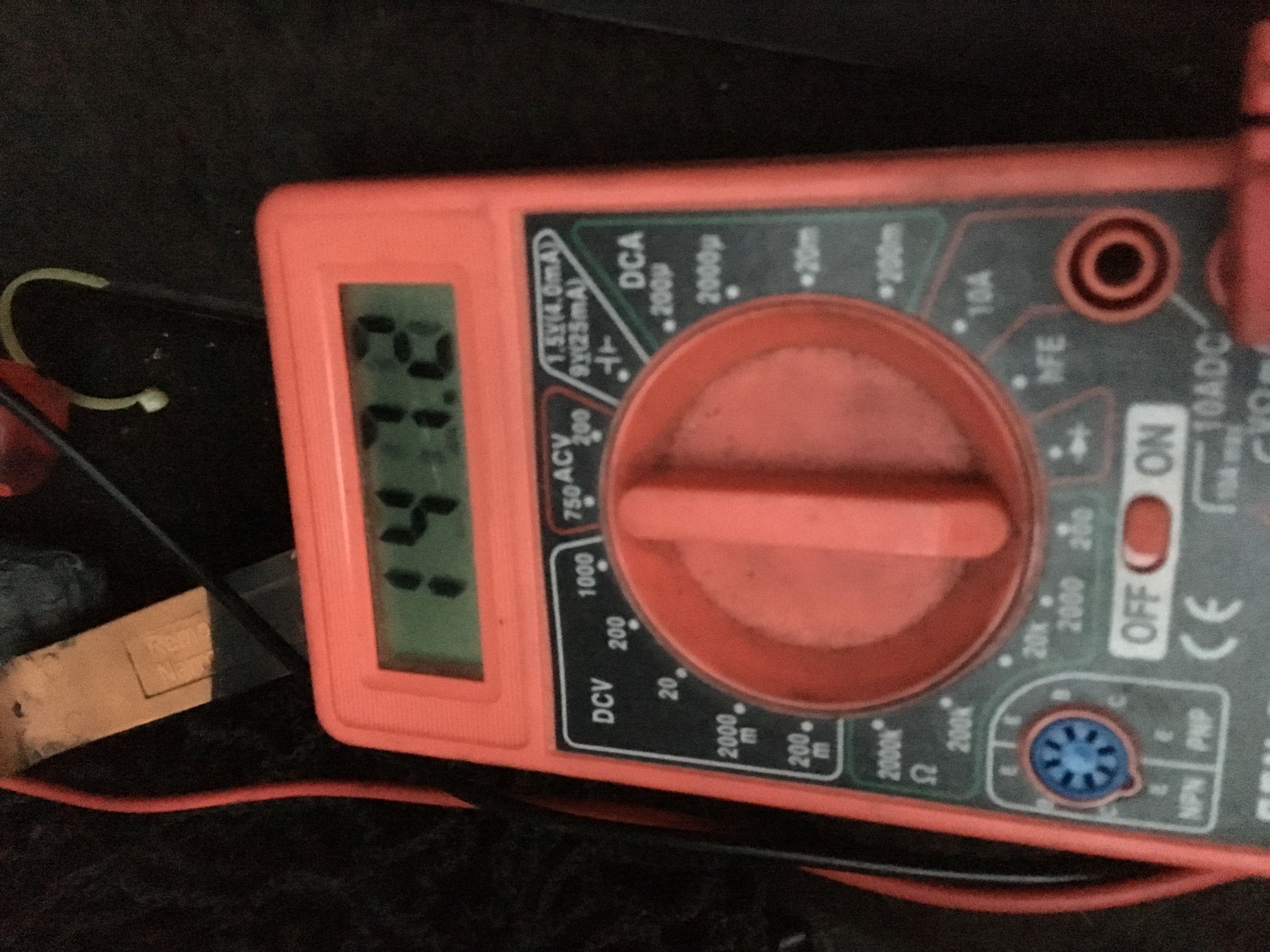
The only pin that shows any continuity at all is number five, and it jumps around and is showing fairly high resistance. Interestingly this is without grounding the wires that I cut the ring connector off.
When I grounded the two exposed wires that I cut off to the new ground points that I created I it showed values above this and they were inconsistent, so the resistance was variable.
Hi There,
Quick note about grounding electrical systems: In general, its important that you use the manufacturer intended ground connections - the primary reason for this is for a local return path for the local current.
This is hard to visualize if you don't have an electronics background, but, your car chassis ground is different from your connector signal ground - even if they have the same voltage potential. They're different in the type of currents they pass.
The chassis and signal ground points serve different purposes: The signal ground wire in the connector to the component is the reference ground for the signal, and, all return currents from this signal flow through this ground wire. If you don't have this ground wire connected properly, the return current has to find another path and will not produce the same behavior at the component. Grounding a signal return to the chassis doesn't necessarily give this local signal a return path for the current.
Hope that makes sense the way I wrote it...
Regards
Mike
P.S. In case you're wondering, I'm an electrical engineer.
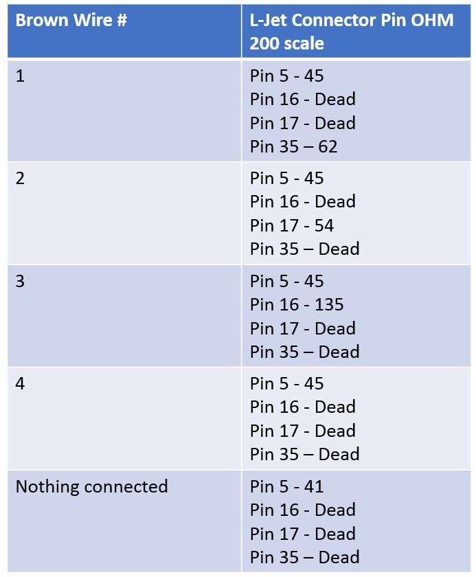
What resistance do you have when you check continuity between the pins on the L Jet connectors and the wires that were disconnected at the ground (ring) connector in the engine bay.
When doing this you would have 1 lead from your multimeter connected to ONE of the terminals 5, 16, 17 and 35, and the other lead from your multimeter connected to one of the individual ground wires at the point in the engine bay where you have cut off the (ring) connector.
This would be my first check to prove whether or not the wires go where we think they go. I would be surprised if all 4 are damaged.
I can't seem to edit my post #97 ^^^^^^
When you connect to the individual ground wires in the engine bay, connect to each one individually to find out the resistance of the individual wires.
Just to try again I cleaned the four engine bay brown ground wires on the passenger side and put terminals on them. All are dead, so don't think I have any choice left but to cut he brown wires in the Injection Harness near the L-Jet to ECU connector.
So I took a deep breath and cut and spliced the brown wires near the L jet connector. I have essentially no resistance / very low resistance now at pins 5, 16, 17 and 35 using the engine compartment cross brace as a grounding point.
I replaced the battery strap with a new one to remove that as a potential issue.
Going by the 84 wiring diagram,
From the control unit
Pin 5 - goes to ground 11 (2) valve cover.
Pins 16,17 and 35 - go to ground 1 valve cover. Note that at ground 1 valve cover has a 4th wire going to it from the tester connection point.
I suspect the four wires you have cut are at ground 1 valve cover.
Given the resistances you have posted, I would find ground 11 (2) valve cover and verify that pin 5 goes there.
I suspect there appears to be a problem within the harness (as others have suspected) and you are picking up a 'loop' of resistance through the various wires.
It may be possible to find the resistance point (probably a kink in the loom where the wires are broken) by connecting your multimeter across one of the pins and one of your 4 wires and have someone watch the resistance on the multimeter while you wiggle or move the harness to see if the resistance varies.

 06-20-2017, 11:52 PM