When you click on links to various merchants on this site and make a purchase, this can result in this site earning a commission. Affiliate programs and affiliations include, but are not limited to, the eBay Partner Network.
Turn steering wheel with steering shaft removed...
Hello All...
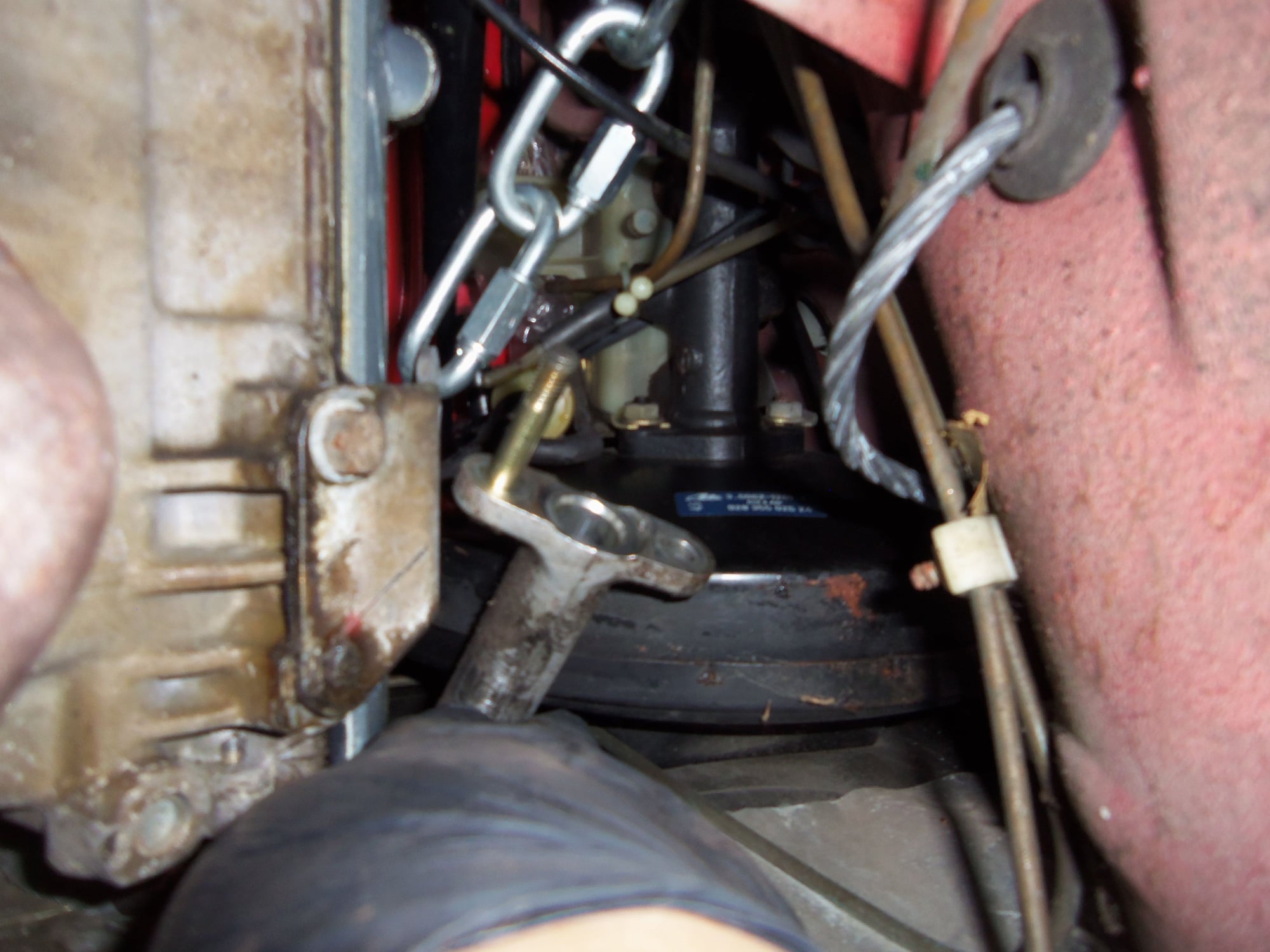
I have removed the lower steering shaft at the rag joint on the Red Witch.
When I removed the steering rack, I had centered the rack and the steering wheel. I have not moved the steering wheel since.
Tonight, removing the steering shaft required some violence and brutality due to one of the studs spinning in the end of the upper shaft. During that, I may have turned the shaft/wheel one turn. The wheel is centered again.
Sooooo...here is my question: are there stops in the steering column that stop the wheel? I am not familiar with a 928 steering column. Is there something that will be broken from turning the wheel too many times in either direction?
If I remember, lock to lock is something like 3 turns. If I AM one turn out, will the additional 1.5 turns break something?
And for the really stupid question...can/how do I properly recenter the steering wheel in respect to the column internal workings?
A few months ago, I tried to remove the lower steering shaft to replace the rubber disc for the rag joint. I was working from above, using a long offset 13mm box end wrench to try to break loose the bottom set of nuts. That is when I learned one of the studs in the upper shaft was spinning. At that point, I elected to leave it alone.
Tonight, while under the car looking at things in general, I had an AHA! moment.
I could clearly see the downward facing retaining nuts for the rag joint. I had clear access to get a battery powered impact gun up there. Removing those nuts would let the entire rag joint and lower steering shaft come off. I could deal with the spinning stud on the work bench.
Idiot. The spinning stud WAS one of the downward facing ones. Well, in for a penny, in for a pound. This thing was coming off, or else.
It took an hour or so, violence, and some good curse words, but I got it off. I ended up wedging a screwdriver between the upper shaft flange and the rubber disc. I pried down to apply downward pressure on the spinning stud. It worked!
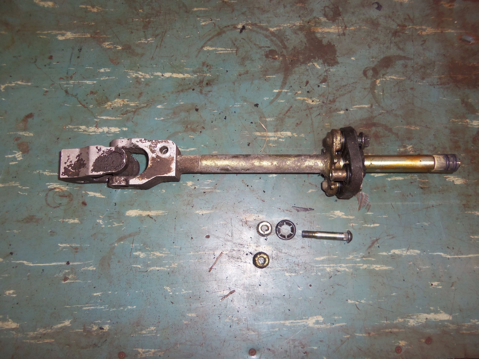
Before that, I took several photos showing the orientation of the lower U-joint, rag joint, and the entire shaft with the steering wheel centered. I want to get this back together properly.
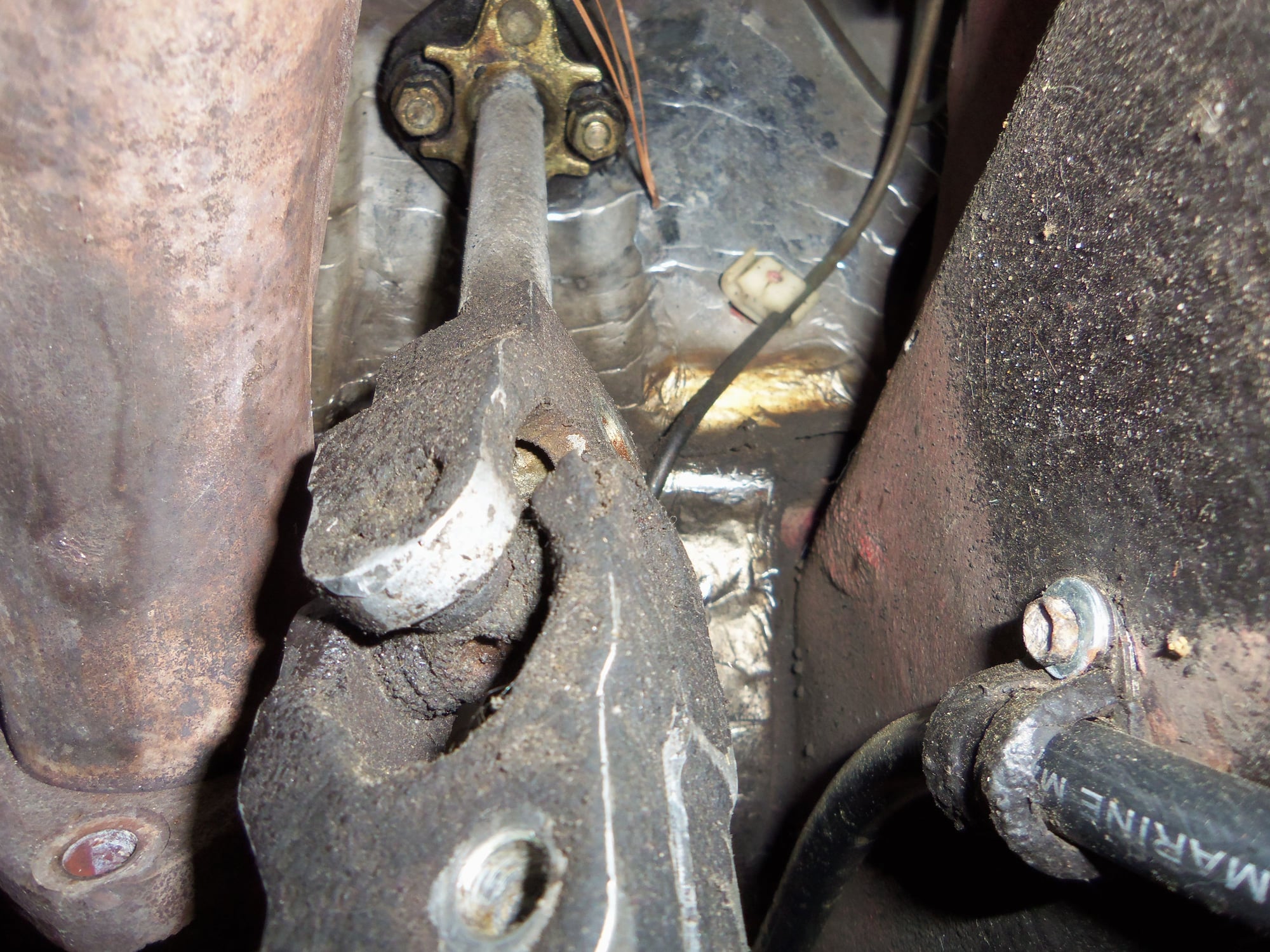
Lower U-joint.
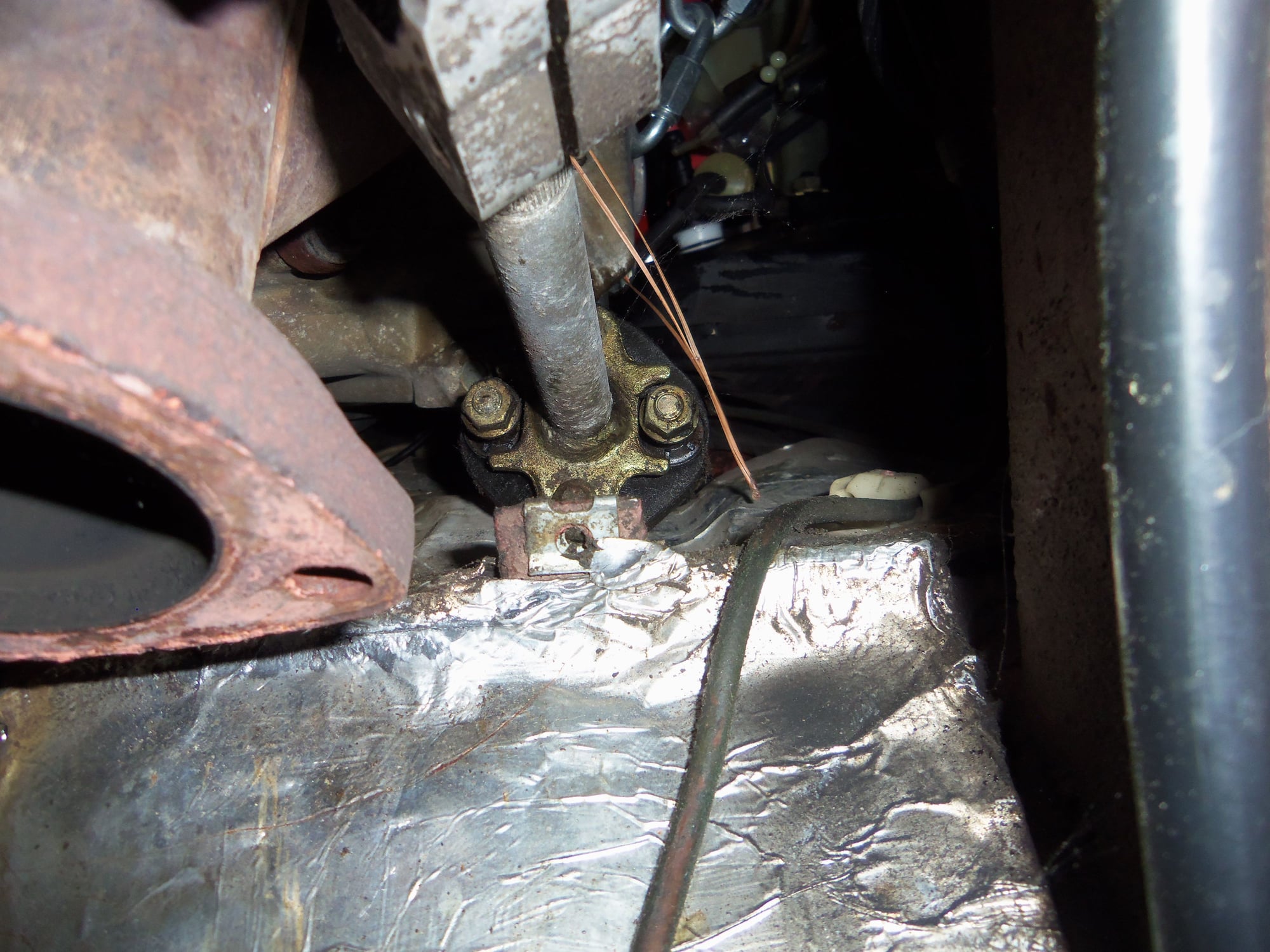
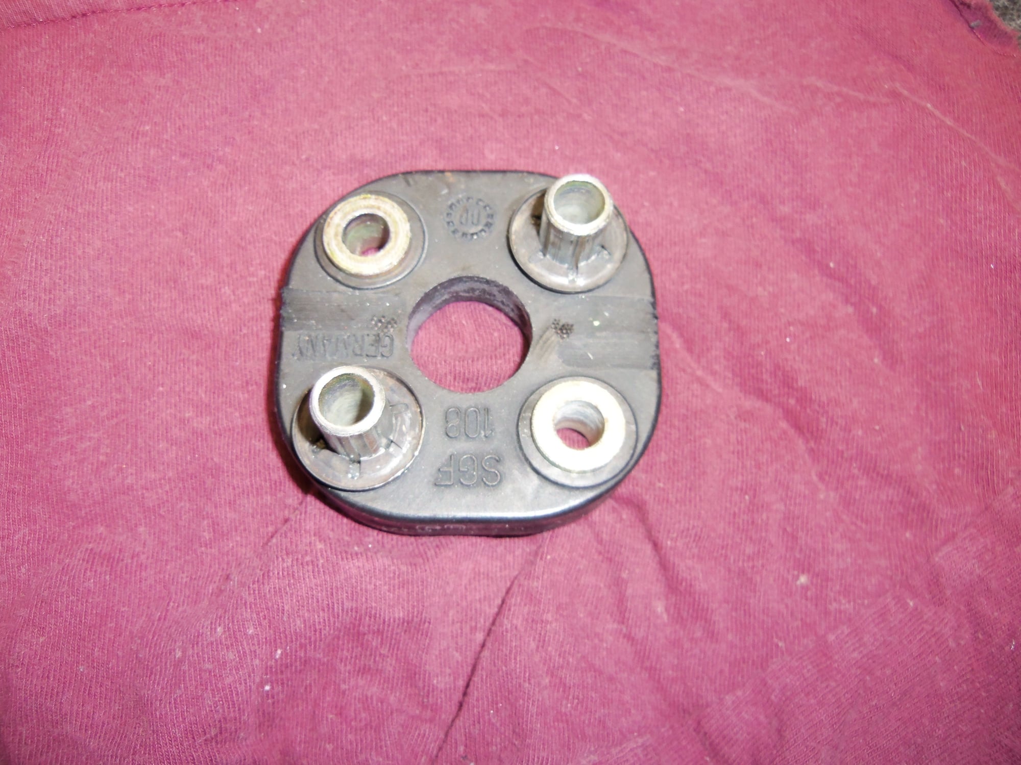
Rag joint. Notice the downward facing nuts are pretty much horizontal. Good reference.
U-joint showing alignment.
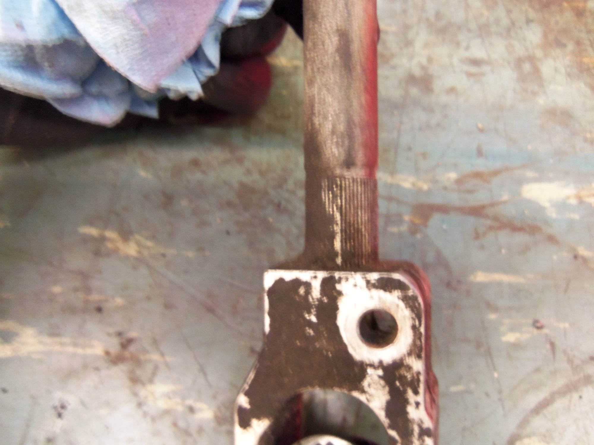
U-joint to lower shaft bolt hole.
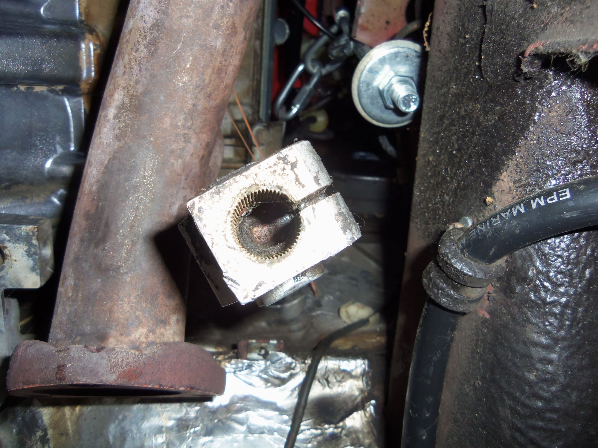
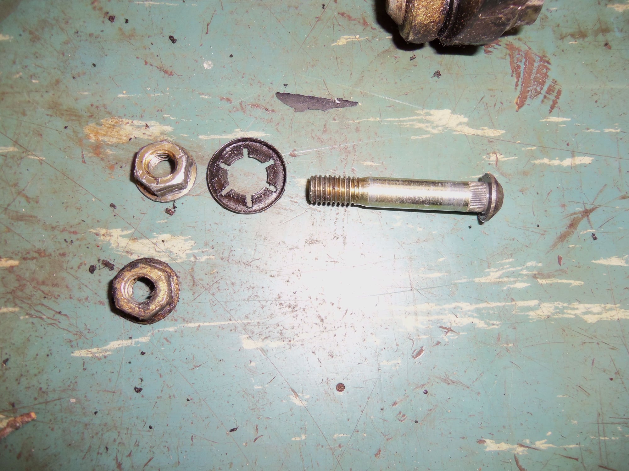
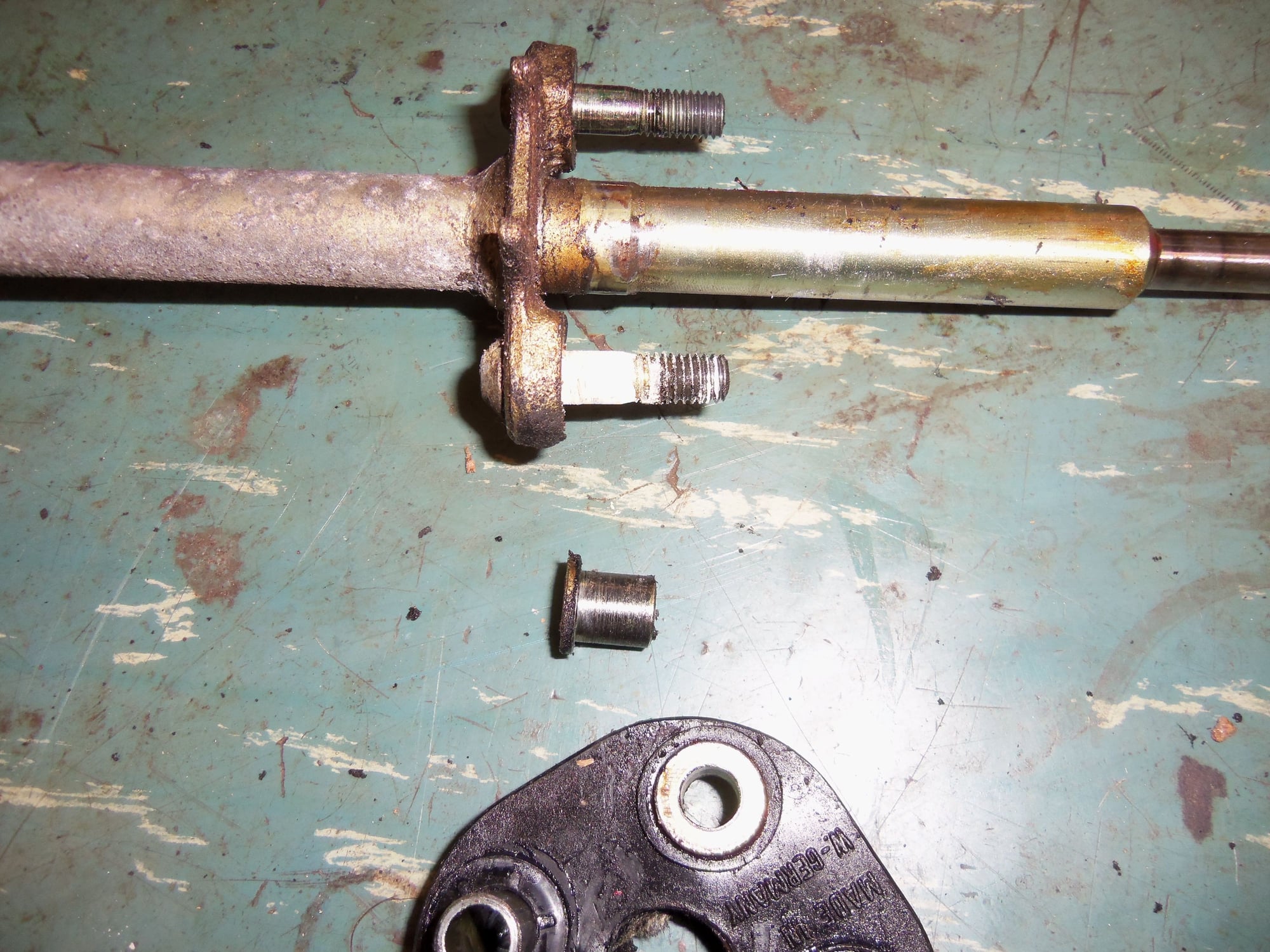
With the lower steering shaft removed, I gently tapped out the spinning stud.
Spinning stud removed.
Looks a little toothless...
Once I got the shaft and parts on a work bench, I was able to get a closer look.
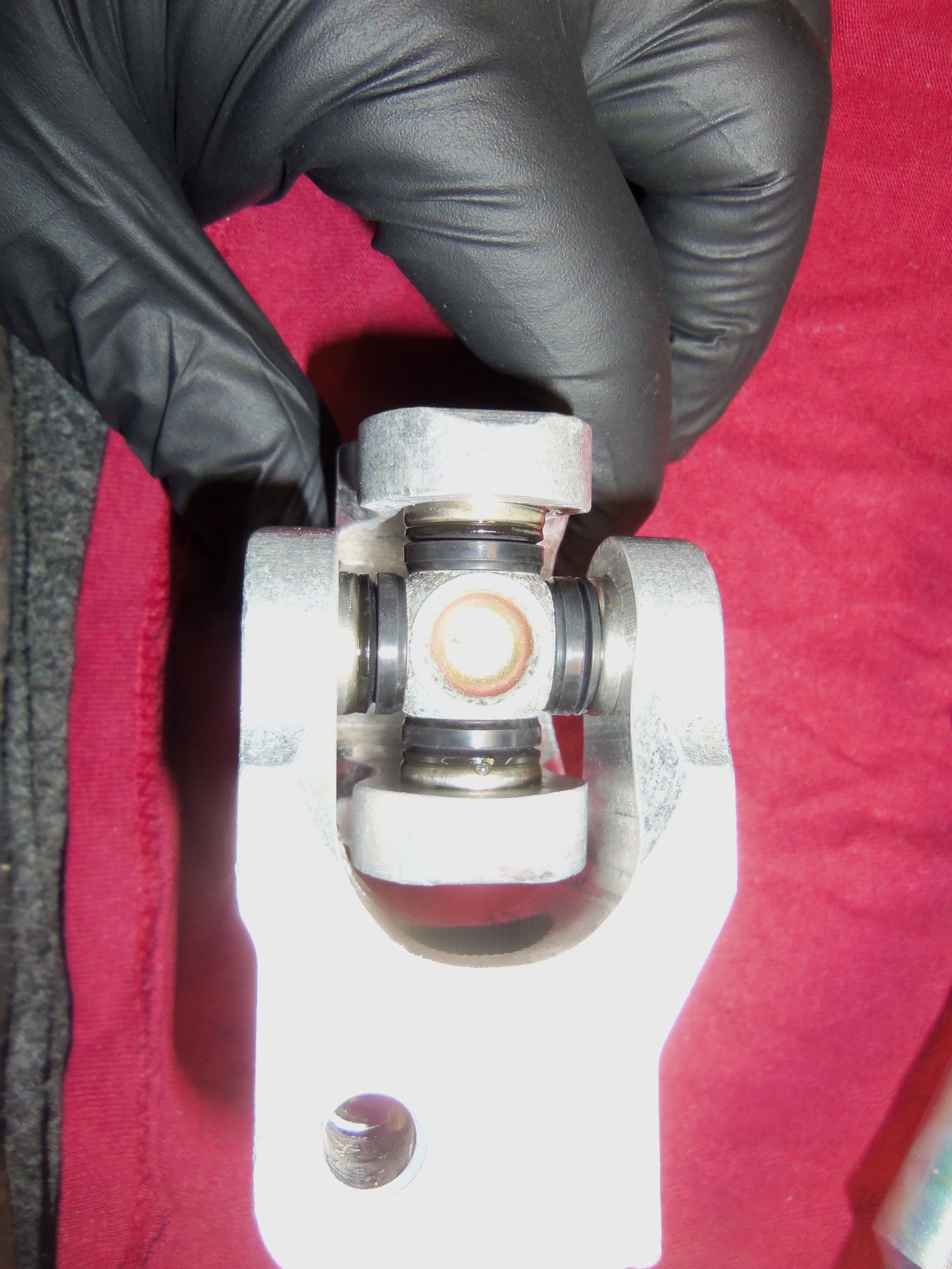
Good: lower U-joint is nice and tight, and does not show any leakage from any of the joint seals.
Bad: the splines are perfect on the spinning stud. That means the hole is wallowed out in the flange on the upper shaft.
I am of two minds on how to deal with this:
1) use a punch or chisel and dimple the h*ll out of the splined area on the stud. This SHOULD let it grab the hole in the flange better.
2) just get a matching length bolt. There is clearance to get my big paw up there to hold a backing wrench.
I will think on this at work as I clean the parts.
All the parts now have a date with the heated parts washer at work. There is a layer of under coating on the lower U-joint. Previous experience cleaning front suspension parts in the heated parts washer shows that this will loosen the under coating.
I have made match marks on two sides of the end of the U-joint and the matching splines where it meets the lower shaft. I don't want to get the upper and lower U-joints out of phase.
I plan on using the heated parts washer to help me get the U-joint off the shaft. I want to thoroughly clean everything, then put antiseize on the splines of the shaft upon reassembly.
I am thinking of using a needle grease injector to lubricate the U-joint cross. I have to look closer at it after cleaning.
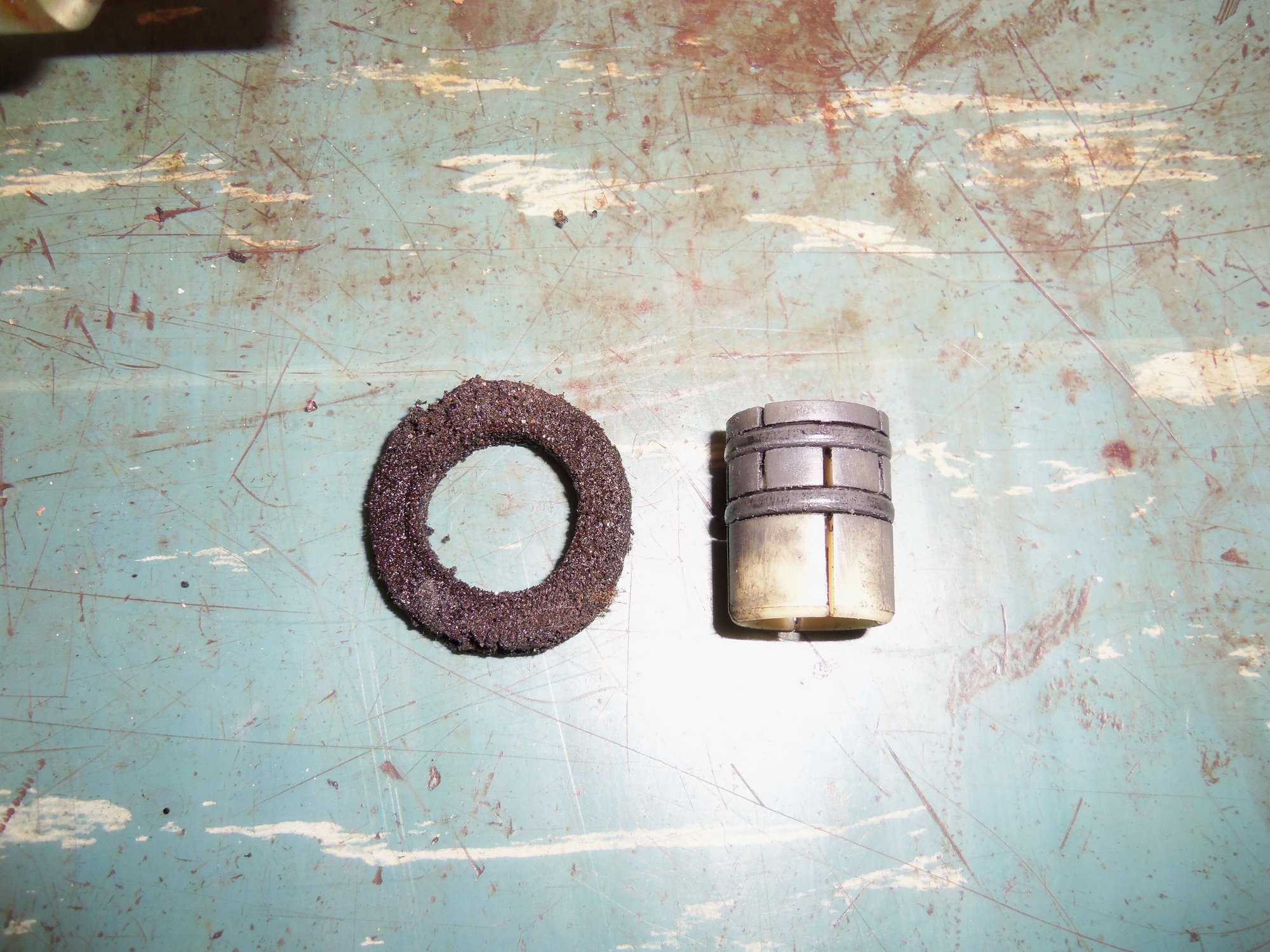
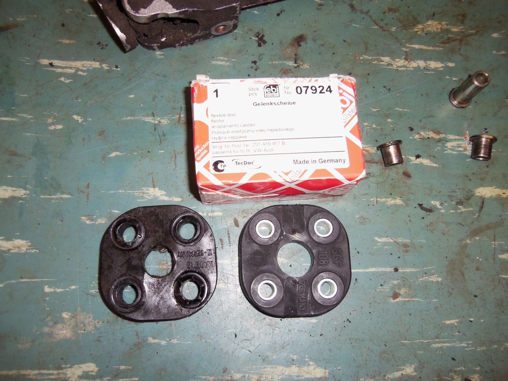
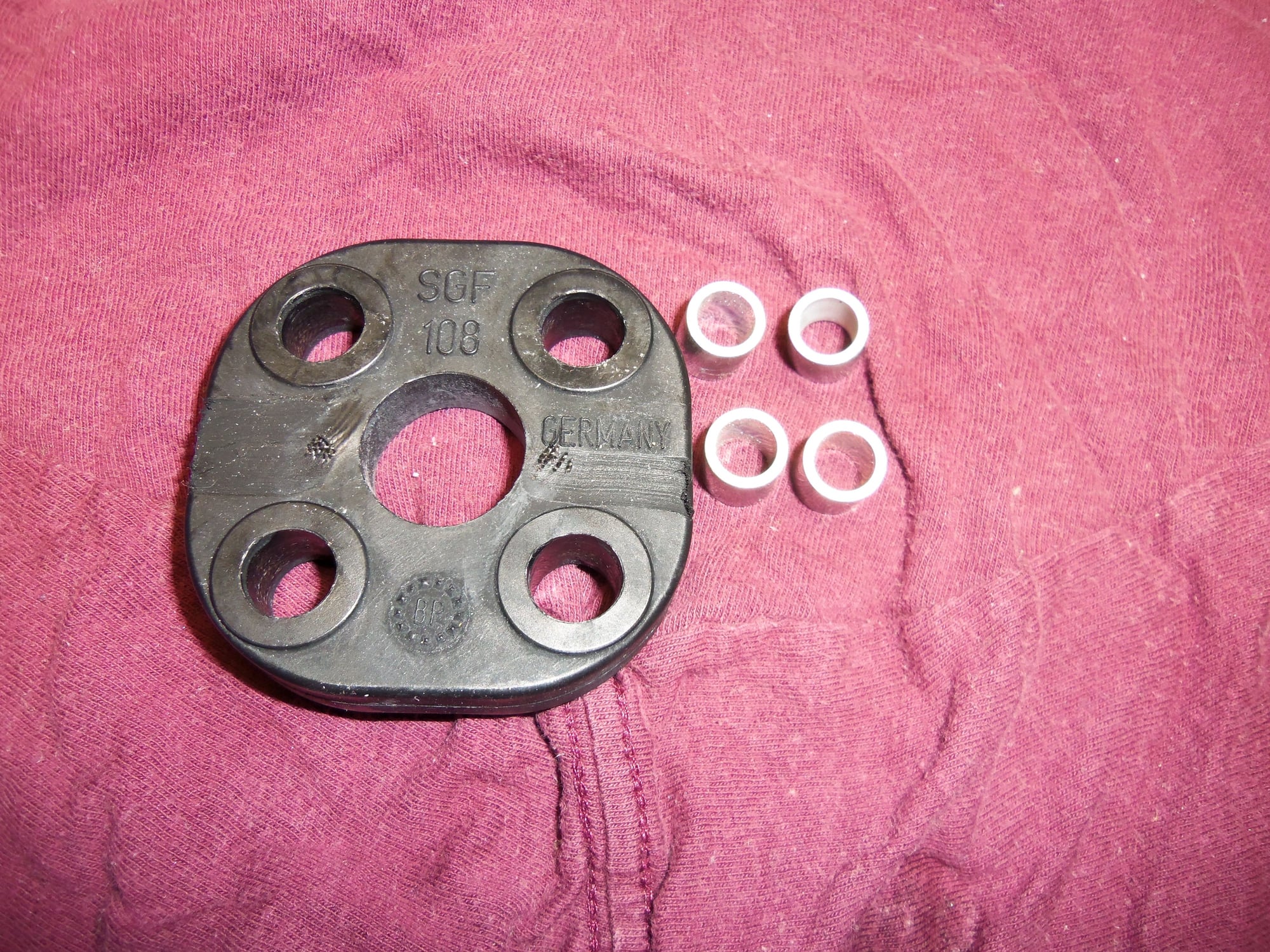
The new rubber disc supplied by Roger will work just fine once I press out the spacers, and press in the spacers from my rag joint.
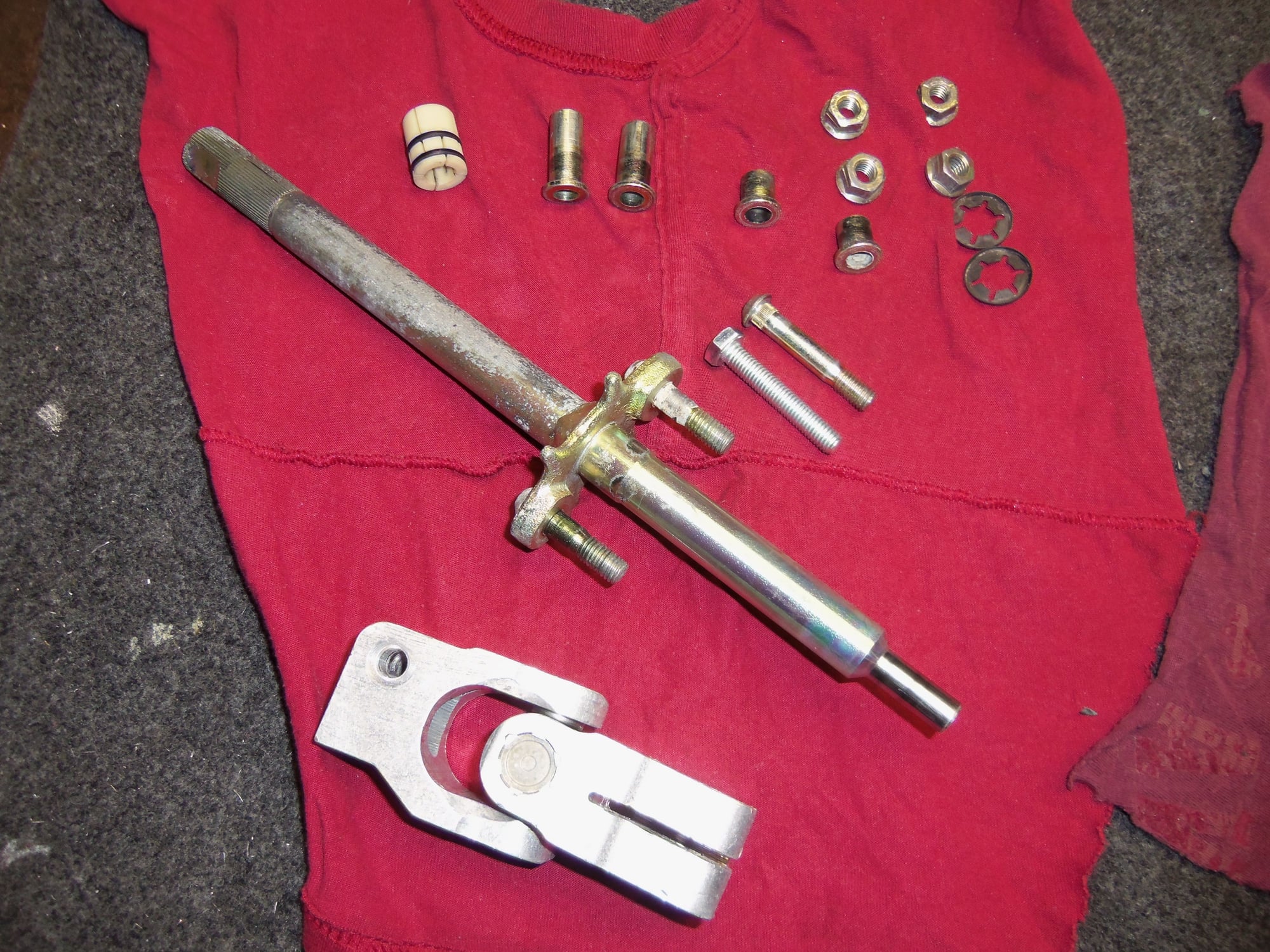
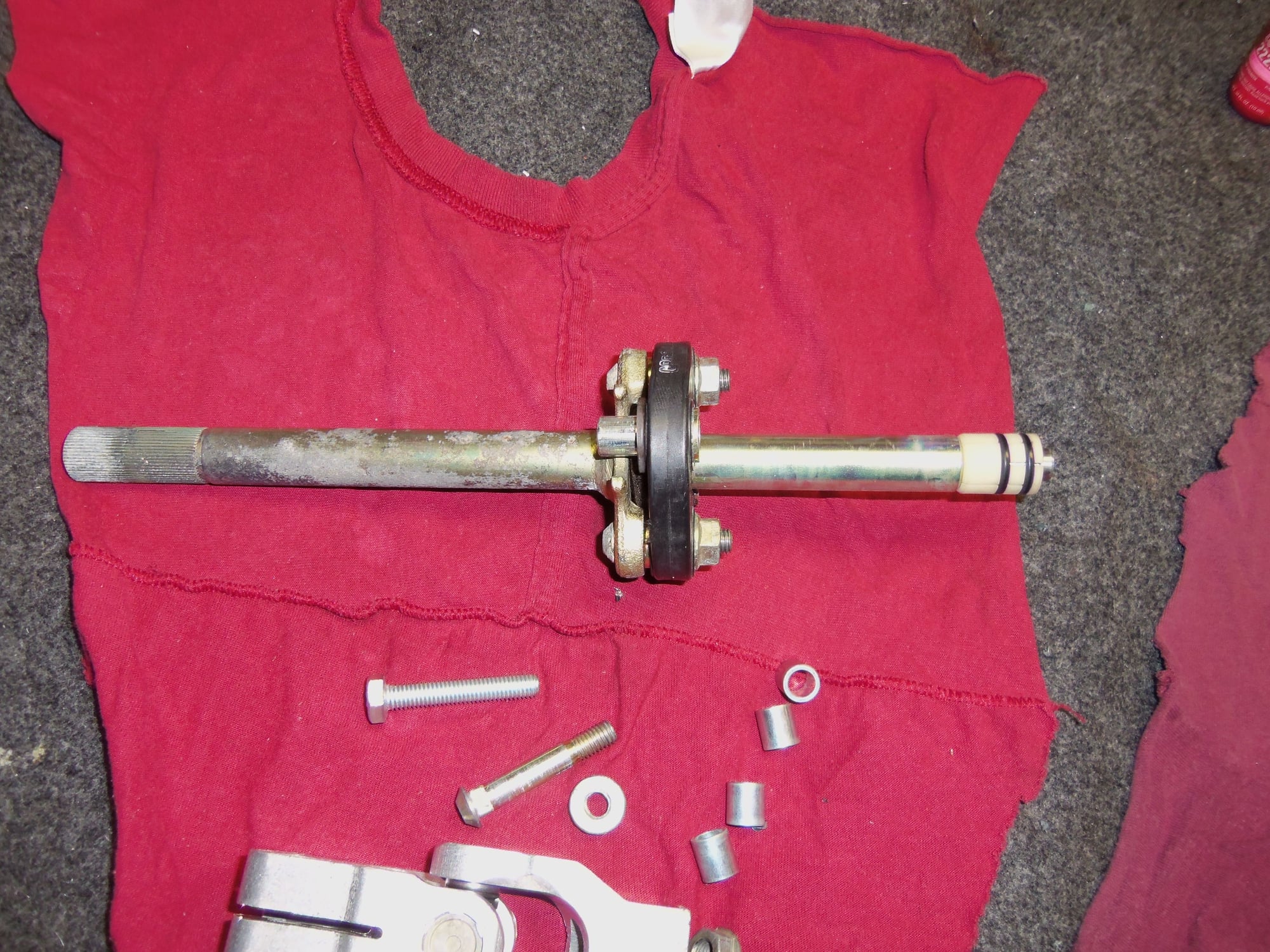
Lower steering shaft, in all its dirty, lightly corroded glory.
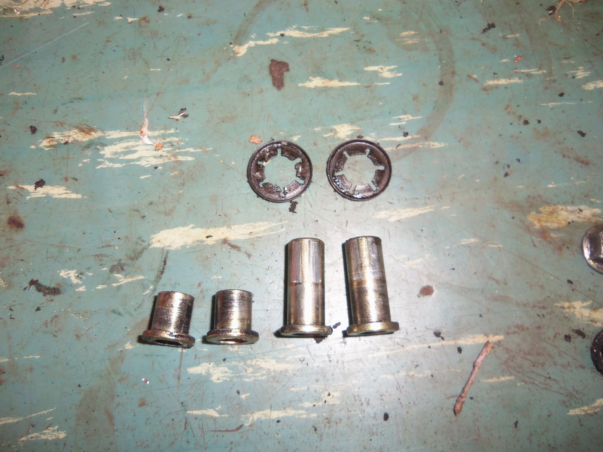
Lock nuts, push on retainer for one of the long spacers, and the d*amnable spinning stud.
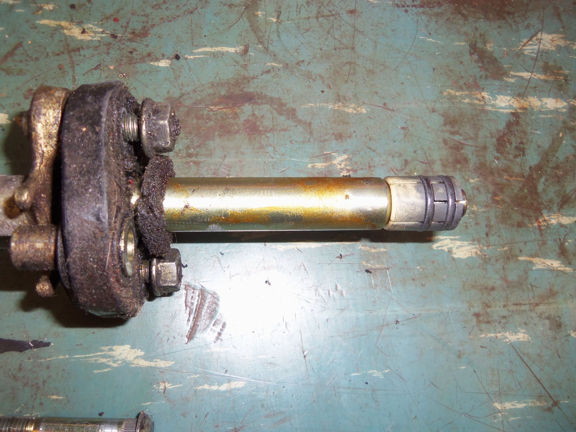
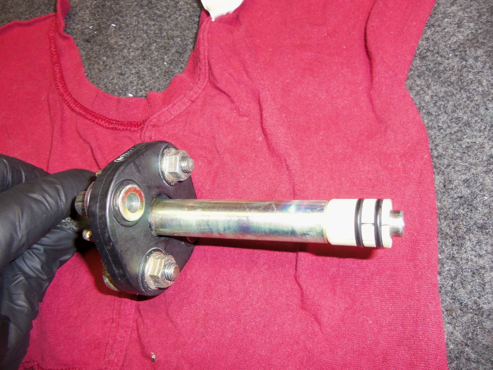
Upper end of the lower shaft, which fits up into the lower end of the upper shaft. Say that three times fast...<br/>Also can see the dust seal just above the rubber disc and the plastic bushing at the top of the shaft.
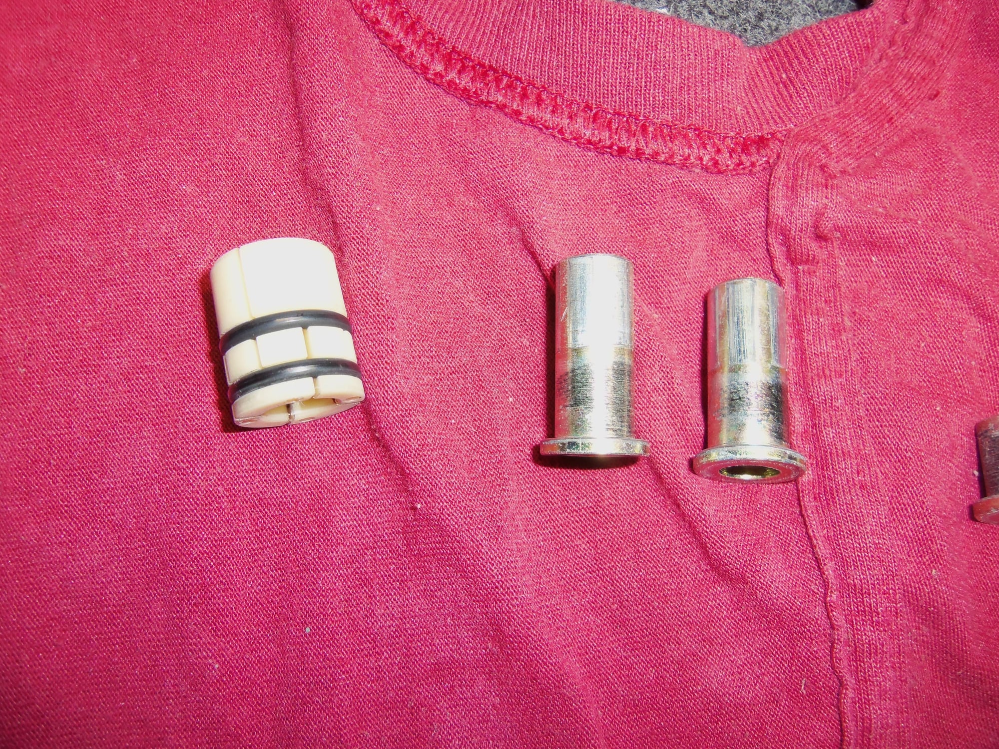
Dust seal and bushing.
Dust seal and bushing, showing O-rings.
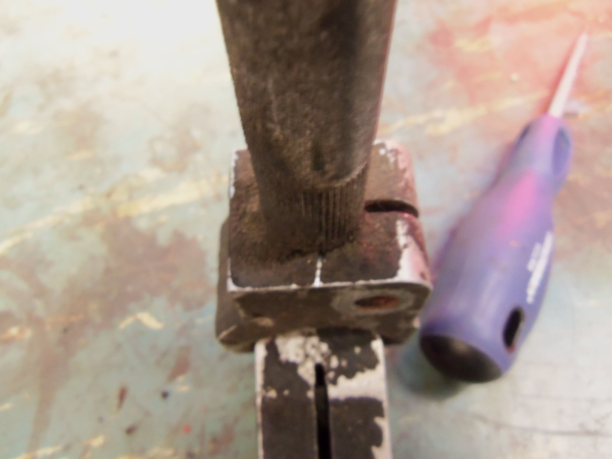
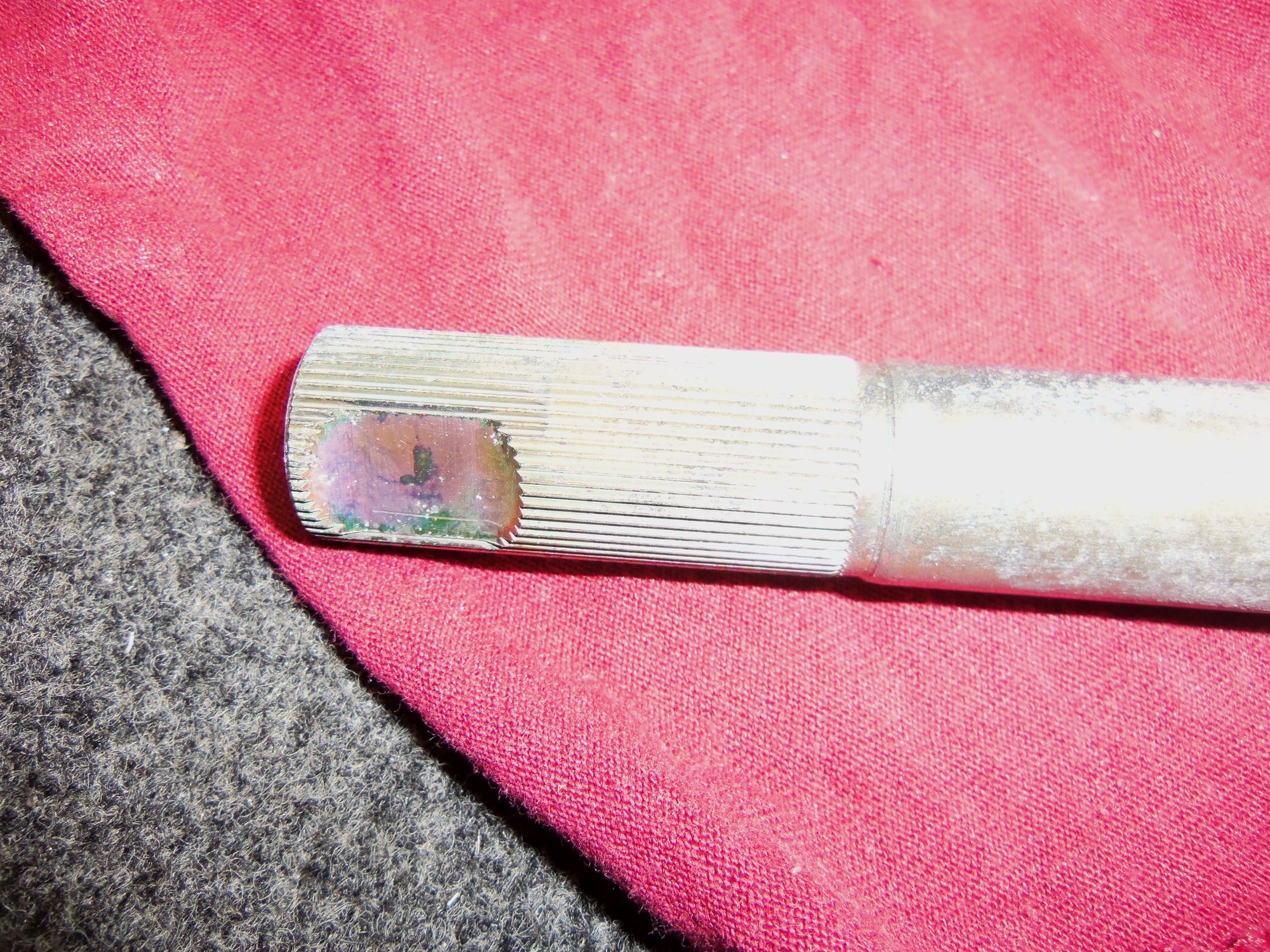
Necked down portion of the shaft.
Flange on the lower shaft. One of the short spacers was slightly corroded to its stud.
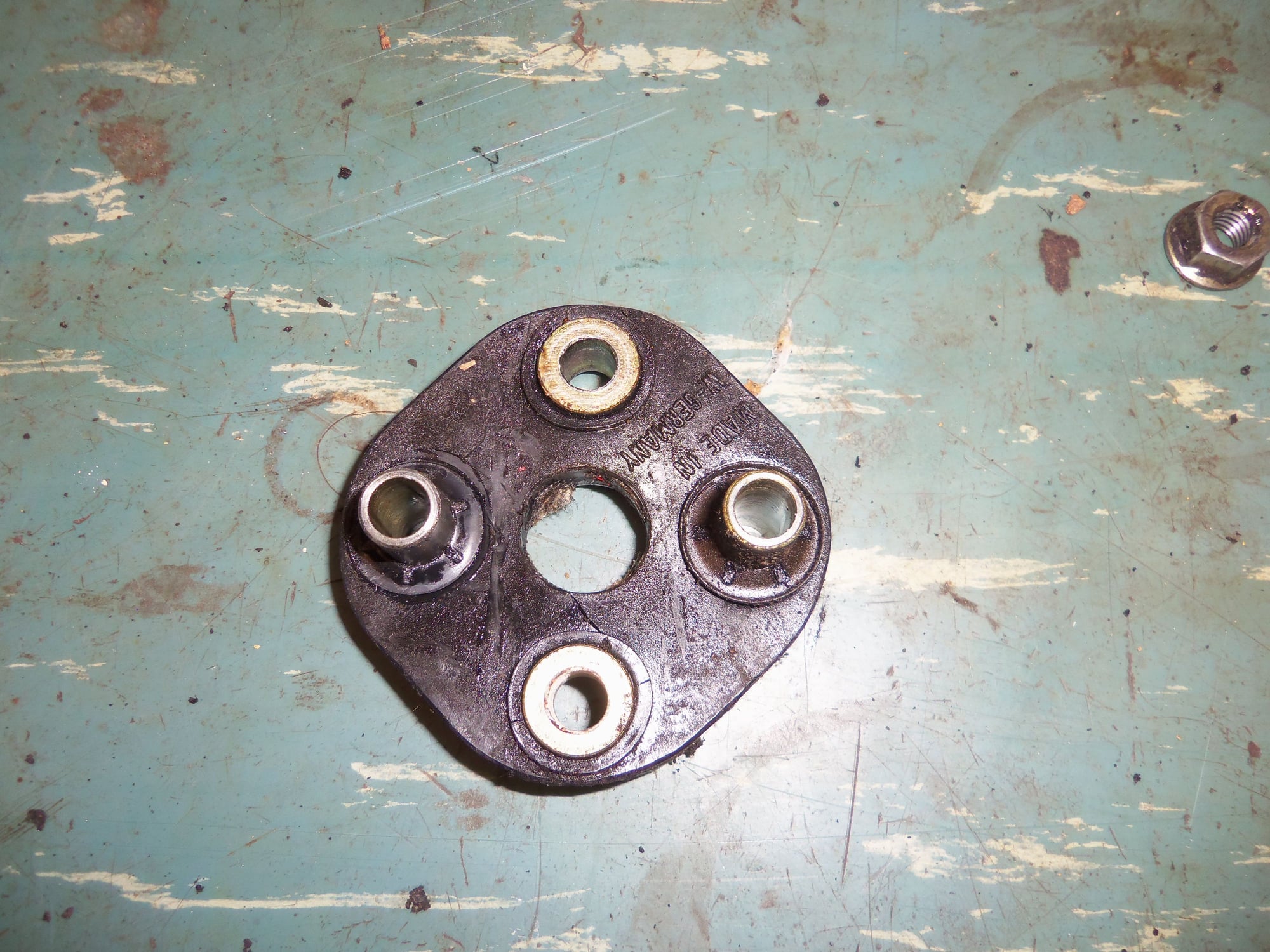
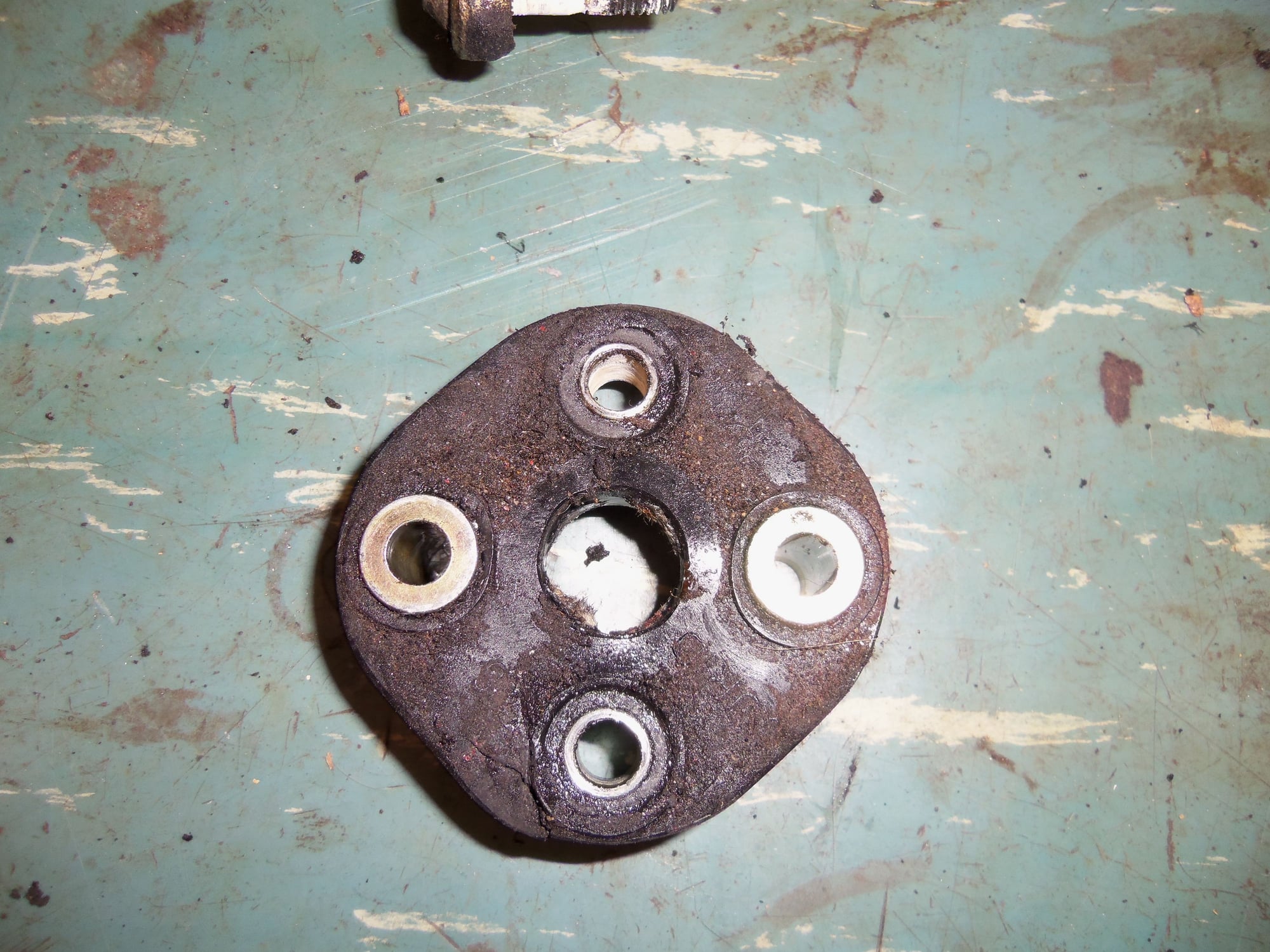
Rubber disc showing long spacers facing up. Flanges on short spacers are facing up.
Rubber disc showing short spacers facing up. Flanges on long spacers are facing up.
Other than dirty, and a little corrosion on a stud, the flange looks OK.
Old rubber disc is still semi-flexible, but it is 30 years old.
Short and long spacers, with retainers for long spacers.
Match mark on splines on one side of the U-joint.
Matching mark on the body of the U-joint.
Will try to reassemble this early next week. I have to work tomorrow night and all weekend.
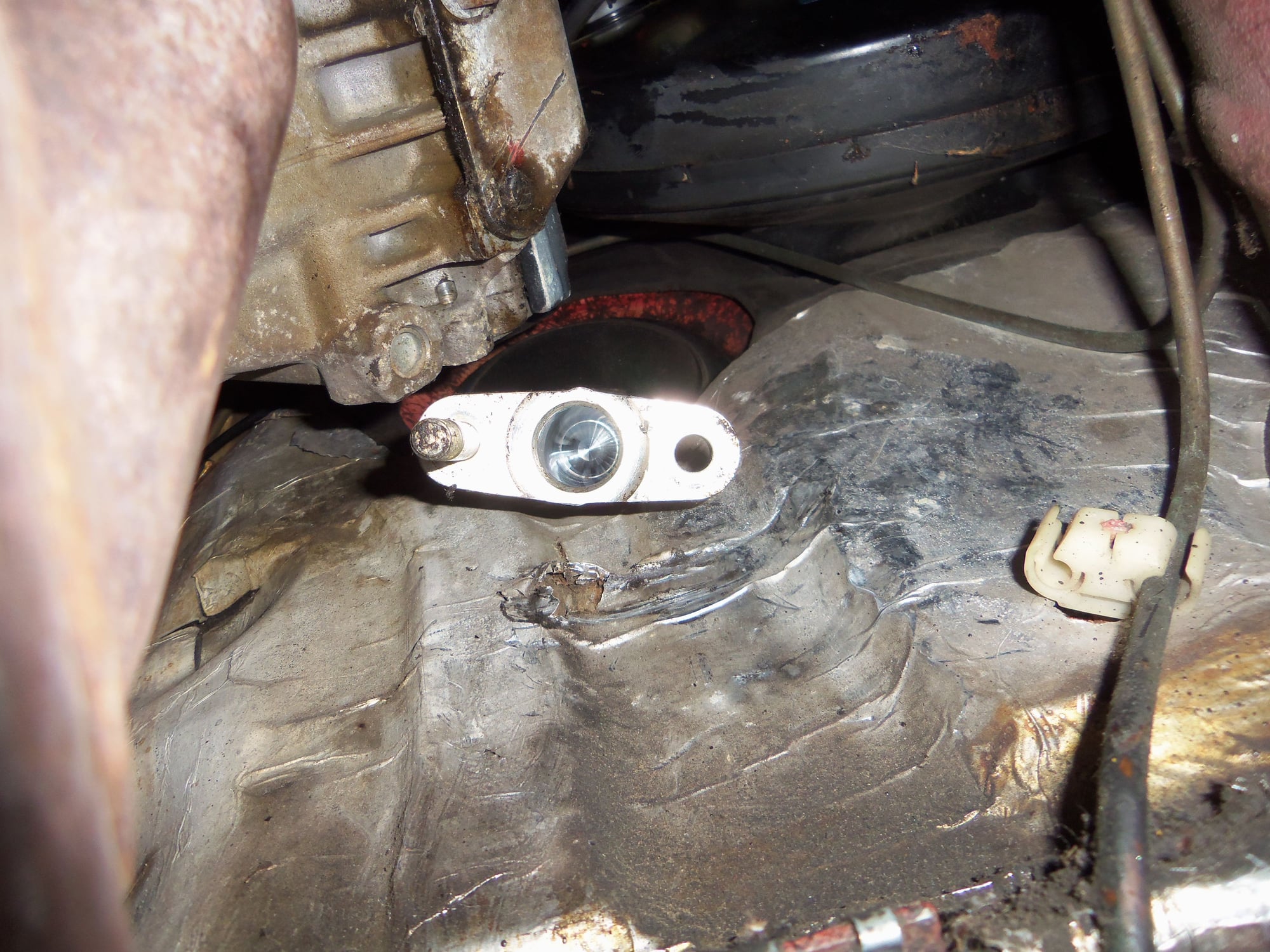
With the steering rack out you can spin the wheel as long as you wish until you get bored. When you have the rack and shaft reinstalled, remove the plastic plug on the rack housing and turn the wheel until you see a depression in the internal steering shaft. This will show you when the rack is perfectly centered left to right. You can take a bolt that will thread into that hole and grind the end into a tip that will fit into that depression and lock the rack in that position. See where your wheel ends up, lift it off the splines, realign and install it, you are good to go.
This does not guarantee that driving down the road your steering wheel will be perfectly aligned; that depends on your alignment which at this point you will need redone. Tell the shop that the steering wheel and rack and properly aligned.
I am aware of the pointed bolt and notch in the steering rack. I did that before I took the rack out. When I put the rack back in, the bolt will hold the rack, and my wife will hold the steering wheel. That SHOULD let me get everything installed straight.
Very glad to know the steering wheel won't be an issue.
Just use JB Weld in the stud hole. No need to over complicate things. As for the steering wheel......the splines are the same on both ends of the shaft so if the wheel is off centre, just remove it and re install when it's straight.
Bonding the stud in has no effect on the safety or integrity of the steering system. It just holds the stud while tightening the nut.I would not deface the stud in any manner.
Dave
Last edited by outbackgeorgia; 06-16-2017 at 08:27 PM.
Reason: Spel
Here's a link to the technical data sheet for 680.
Thanks! I will look into this.
Originally Posted by Imo000
Just use JB Weld in the stud hole. No need to over complicate things. As for the steering wheel......the splines are the same on both ends of the shaft so if the wheel is off centre, just remove it and re install when it's straight.
Thanks Imo000. That makes sense. I have found an M8 x 45mm bolt that looks quite promising.
Will do on reorienting the steering wheel.
Originally Posted by outbackgeorgia
Bonding the stud in has no effect on the safety or integrity of the steering system. It just holds the stud while tightening the nut.I would not deface the stud in any manner.
Dave
Did some cleaning and minor reassembly tonight at work.
Somebody changed the solvent in the heated parts washer. Yay! That made quick work of the dirt and grime on the lower steering shaft.
I was able to separate the U-joint from the shaft with no problems.
I reassembled the new rubber disc to the shaft after pressing in the bushings and retainers. I put a light coat of copper antiseize on the studs on the lower shaft.
I would have reinstalled the U-joint, but I don't have any silver antiseize here at work. I will do that Monday at home.
Nice clean parts.
U-joint cross cleaned up well.
Splines at the end of the shaft.
Upper plastic bushing and two longer rag joint bushings.
I think if it were me, if go back with the original stud. It has an unthreaded shank which will make for a much more precise fit in the yoke as well as the bushing. It is also in single sheer so will probably be much stronger the putting the threaded section of that bolt in sheer.

 06-16-2017, 12:08 AM