When you click on links to various merchants on this site and make a purchase, this can result in this site earning a commission. Affiliate programs and affiliations include, but are not limited to, the eBay Partner Network.
The equations are �relatively� easy. I normally use engineersedge com (no affiliation) calculators at work. The real trick is you have to know what the exact materials (more importantly, yield strength of said materials) of the mating parts are. In this case what is the bolt material and what is the custom adapter material. From there, convert the torque to axial force and put aside. Determine shear area of the bolt (includes thread engagement), throw a dart at the wall for your proof load (not really, normally 90 - 92% of yield strength) and calculate pre-load force. Repeat for internal thread shear area of adapter. Compare the axial force to the preload forces. 17mm seems like a good length of thread engagement. A good rule of thumb is 1.3 x bolt size (I.e. 1.3 x m14 = 18.2mm thread engagement). SST bolts are normally used for corrosion resistance and it makes sense that they would be sold for caliper kits, but I imagine your beauty won�t have gunk on the calipers long enough to start to corrode. SST is a lot softer than traditional bolt materials. I can help you calculate the torques, if you�d like, but would need to know what material the adapter is made from (I.e. 1018 cold rolled steel or 316 stainless steel) and of course which bolts you were looking at.
The equations are �relatively� easy. I normally use engineersedge com (no affiliation) calculators at work. The real trick is you have to know what the exact materials (more importantly, yield strength of said materials) of the mating parts are. In this case what is the bolt material and what is the custom adapter material. From there, convert the torque to axial force and put aside. Determine shear area of the bolt (includes thread engagement), throw a dart at the wall for your proof load (not really, normally 90 - 92% of yield strength) and calculate pre-load force. Repeat for internal thread shear area of adapter. Compare the axial force to the preload forces. 17mm seems like a good length of thread engagement. A good rule of thumb is 1.3 x bolt size (I.e. 1.3 x m14 = 18.2mm thread engagement). SST bolts are normally used for corrosion resistance and it makes sense that they would be sold for caliper kits, but I imagine your beauty won�t have gunk on the calipers long enough to start to corrode. SST is a lot softer than traditional bolt materials. I can help you calculate the torques, if you�d like, but would need to know what material the adapter is made from (I.e. 1018 cold rolled steel or 316 stainless steel) and of course which bolts you were looking at.
Thanks. I appreciate the help. The studs will be 304 Stainless -https://www.aliexpress.com/item/AXK-1pcs-304-stainless-steel-double-studs-equal-studs-studs-screw-bars-GB901-M14-50-170mm/32899330367.html - these but with a thread pitch of 1.5 instead of 2 so more thread engagement in the same distance (same as a Porsche wheel bolt incidentally). I've ordered both the 120mm and 130mm length to see which fits better without too much stud protruding past the top nut and this will also have the caliper ride on a non-threaded portion of the fastener, like the OEM bolts are designed. The top nuts will be Titanium Flange Castle nuts and I am going to drill them for a cotter pin to go through the castle nut just to be safe.
How do you like your one piece aluminum drive shaft?
Any regrets or downside? How many miles on it now if you don�t mind sharing.
Very happy with it. No issues and nice to never have to worry about the bearing support again. It has about 3,500 miles on now. Round trips of 20 hours, 10 hours, 6 hours, and some around town driving as well. Nice direct feel between throttle pedal and wheels too.
Very happy with it. No issues and nice to never have to worry about the bearing support again. It has about 3,500 miles on now. Round trips of 20 hours, 10 hours, 6 hours, and some around town driving as well. Nice direct feel between throttle pedal and wheels too.
Thank you so much for your feedback, I will go with the carbon fiber version soon. Great job on your build.
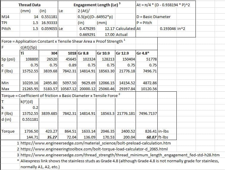
Sorry it took so long to get back. Researching Stainless was more involved than originally thought. I've crunched the numbers for you, and have attached them as a screenshot. Perhaps another M.E. can chime in and validate my calcs, but it looks like you're going to start stretching those stainless bolts at about 70 ft-lbs of torque. If you have any questions about the screenshot, let me know.
Last edited by Oahni; 09-16-2018 at 01:34 AM.
Reason: added screenie
Thank you so much for your feedback, I will go with the carbon fiber version soon. Great job on your build.
Thanks a lot.
I considered the CF version myself, but went for the solid aluminum one for a few different reasons:
It was less expensive
I wasn't sure if the torsional elasticity of the CF version would feel smoother or feel odd. The aluminum one has more torsional rigidity and the carbon one was supposed to be smoother, which to me means instead of transferring the power directly to the wheels, the driveshaft actually winds up a little and then releases and untwists itself later and/or more gradually. I'm very pleased with the direct feel of the aluminum one and don't have any personal experience with the CF one but could see where it might feel either a little vague or snappy.
Since I plan to keep my car for a very long time (we're talking over a decade) and the point of replacing the stock driveshaft setup was so I'd never have to worry about a cardan shaft failure, it seemed like a safer bet to go with a single construction material (solid aluminum one), instead of the carbon fiber that is somehow mated to the metal ends where the fastening method could at sometime separate, the CF might become brittle over time from heat exposure or stress fatigue, or other issues I may not have though of.
Maybe the CF one is even better and none of these concerns are a factor, I just don't know. Also, make sure to take a measurement of exactly where your bearing support is located and have them avoid putting any balancing weights in that area. We had to adjust my engine cradle to have the weights not contact the top half of the bearing support bracket that is no longer used, but still remains as part of the vehicle.
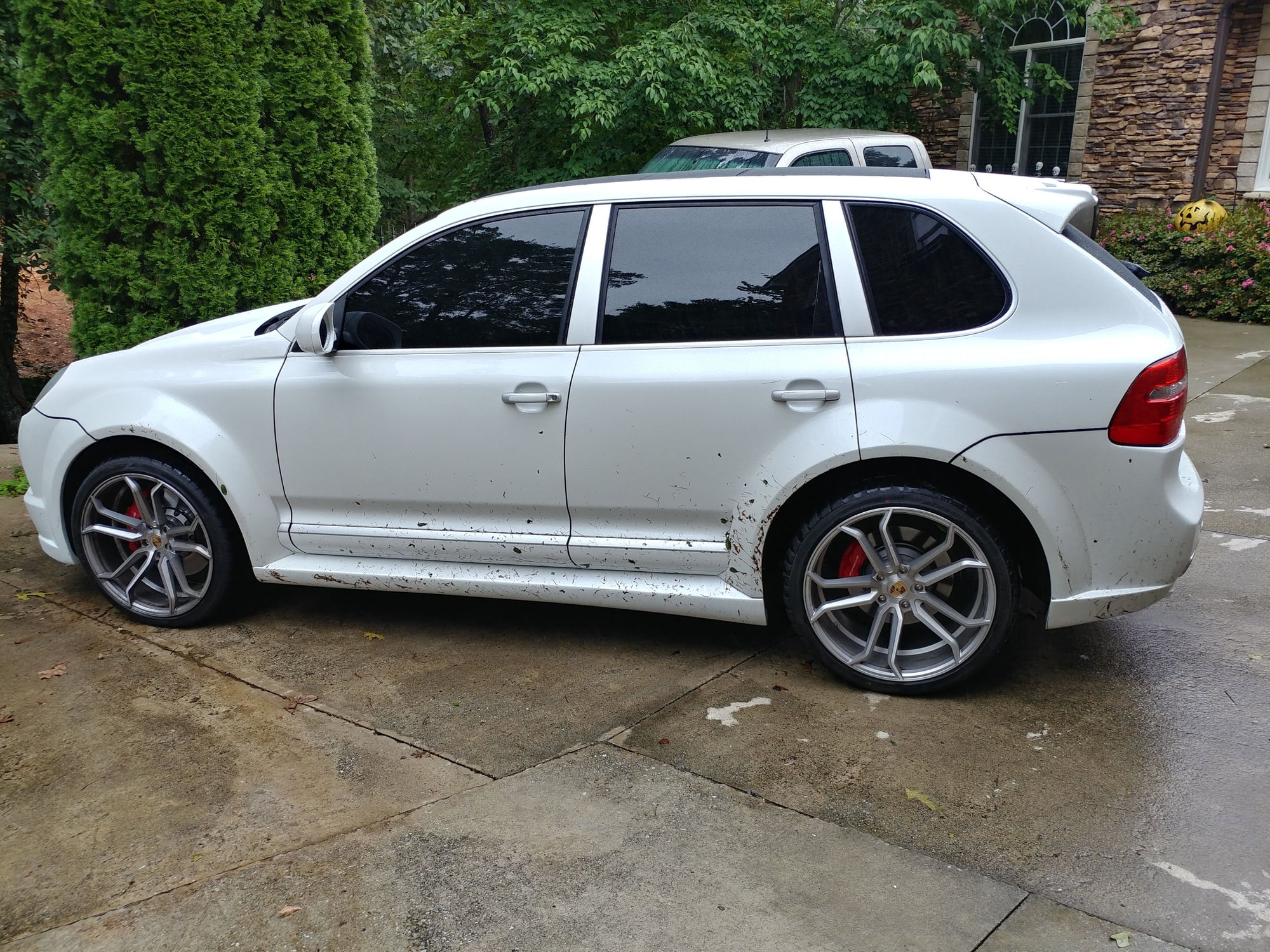
Poor Cayenne. We needed to run up the mountain today to do a little birthday shopping for my daughter at some boutiques. We were having some steady rain and some wind from the residual hurricane (Florence) and decided to take the Cayenne over the pickup due to its better stability control, less sway in the curves since my daughter gets car sick, and so we could keep the purchases dry. There was pretty steady rain and a bunch of leaves and debris on the road. The Cayenne and the Aturro tires worked perfectly.
I felt bad so hosed off the debris before putting her back in the garage.
I considered the CF version myself, but went for the solid aluminum one for a few different reasons:
It was less expensive
I wasn't sure if the torsional elasticity of the CF version would feel smoother or feel odd. The aluminum one has more torsional rigidity and the carbon one was supposed to be smoother, which to me means instead of transferring the power directly to the wheels, the driveshaft actually winds up a little and then releases and untwists itself later and/or more gradually. I'm very pleased with the direct feel of the aluminum one and don't have any personal experience with the CF one but could see where it might feel either a little vague or snappy.
Since I plan to keep my car for a very long time (we're talking over a decade) and the point of replacing the stock driveshaft setup was so I'd never have to worry about a cardan shaft failure, it seemed like a safer bet to go with a single construction material (solid aluminum one), instead of the carbon fiber that is somehow mated to the metal ends where the fastening method could at sometime separate, the CF might become brittle over time from heat exposure or stress fatigue, or other issues I may not have though of. Maybe the CF one is even better and none of these concerns are a factor, I just don't know.
Thank you for all your thoughts.
1) As far as the price, I do agree. 30% less, about 500 off.
2) The idea of getting CF is that it absorbs vibration much better then anything else, especially if I eliminate the front "Guibo" (the big rubber piece).
The way I see it, if you hold steel, aluminum and CF shaft in your hand and hit it with a hammer. You will feel huge vibration from the steel, that is why so much rubber is used and it is two-piece design. You will get much less vibration from aluminum and almost no vibration in the same scenario from CF.
I believe that is the reason for it being described as the smoothest option. I believe both shafts will give you more direct feel, I don't thing, the CF will be noticeably snappy as it is 3.25 inch in diameter.
3) Your third point is a great one. I believe the CF shaft is actually rated higher as far as torque capacity than aluminum one, but I can see the longevity for sure on the side of the aluminum one. I agree, that the point of replacing the stock driveshaft setup should be so I'd never have to worry about the shaft failure for as long as I own the car. I might do some more reading on CF longevity, before I decide. I have 957 GTS (6-speed), obviously way less torque then TTS, but the manual tranny abuses the shaft more than auto IMO. I also want to keep the car for a long time, as there won't be another manual GTS in the future EVER.
Originally Posted by Petza914
Also, make sure to take a measurement of exactly where your bearing support is located and have them avoid putting any balancing weights in that area. We had to adjust my engine cradle to have the weights not contact the top half of the bearing support bracket that is no longer used, but still remains as part of the vehicle.
What do you mean by this, I have no Idea what is that you trying to tell me. I thought it was a direct replacement, just plug and play. Please explain.
What do you mean by this, I have no Idea what is that you trying to tell me. I thought it was a direct replacement, just plug and play. Please explain.
It is a direct replacment, however in the photo of mine I posted, you can see that they company positioned the balance weights on the driveshaft at the exact position where the bearing support bracket is part of the car. The reason the OEM Cayenne driveshaft has a center bearing is because where it attaches at both ends actually aren't lined up, they're offset by about 1.5". Instead of going to expense to redesign sub-assemblies to make them aligned, Porsche decided instead to put a bearing joint in the driveshaft, which I'm sure was much cheaper. There is enough clearance for the shaft to go through the tunnel on the slight angle created, providing the driveshaft company doesn't install the weights right in that area, which they did on mine so every time the shaft rotated the weights contacted the vestigal bearing support - I learned all of this after the fact. Leaving it like that, aside from being really noisy and annoying would have probably knocked the weights off and created an imbalance in the driveshaft. Luckily, there was enough play in the position of my engine cradle where it could be shifted to create enough clearance for the weights.
What I recommend you do is that while under the car, take an exact measurement from the driveshaft end attachment points to the bearing support subframe and instruct the driveshaft vendor not to install any weights in that area. If the driveshaft needs weight there, they should add weight somewhere else and rebalance it, which should then make it require weight in a different location than that area.
FOR SALE THREAD IN MARKETPLACE WITH LEFTOVER BUILD PARTS
I've created a For Sale thread in the Marketplace for the leftover and unused parts from this Widebody Build if anyone is looking for replacement or upgrade parts for their Cayenne. The list will grow a little bit over time as I get additional items cleaned up and photographed, but here's what's there so far with photos
Sorry it took so long to get back. Researching Stainless was more involved than originally thought. I've crunched the numbers for you, and have attached them as a screenshot. Perhaps another M.E. can chime in and validate my calcs, but it looks like you're going to start stretching those stainless bolts at about 70 ft-lbs of torque. If you have any questions about the screenshot, let me know.
Oahni, thanks so much for looking into this and doing these calculations. In doing further research on my own, it looks like you're absolutely right and that a stainless 304 material is not a good choice for a 200 ft lb. torque spec on an M14 sized fastener, which I never even thought to check since I default to stainless fasteners for most everything. Looks like I'm going to need to go up to a Grade 12.9 to make it to that spec, though 10.9 may be OK. Ti may also be close enough if torqued to about 150 ft lbs and that should hold just fine. My goal was to prevent constantly unthreading and retorquing into the aluminum wheel carrier, which over time can strip it out, but with the adapter attachment method now, I'll only be attaching that to the wheel carrier once and any brake work can be accomplished by removing the bolts that thread into the steel adapter. 2nd goal was to use a fastener that doesn't rust for ease of maintenance due to the extended service intervals, It might just be safer and make more sense to find a proper grade 12.9 or Ti fastener, as with PCCBs there should't be much pad or rotor wear and the frequency of removing and reinstalling brake parts should be very rare, and even if done will be done into a steel adapter.
It is a direct replacment, however in the photo of mine I posted, you can see that they company positioned the balance weights on the driveshaft at the exact position where the bearing support bracket is part of the car. The reason the OEM Cayenne driveshaft has a center bearing is because where it attaches at both ends actually aren't lined up, they're offset by about 1.5". Instead of going to expense to redesign sub-assemblies to make them aligned, Porsche decided instead to put a bearing joint in the driveshaft, which I'm sure was much cheaper. There is enough clearance for the shaft to go through the tunnel on the slight angle created, providing the driveshaft company doesn't install the weights right in that area, which they did on mine so every time the shaft rotated the weights contacted the vestigal bearing support - I learned all of this after the fact. Leaving it like that, aside from being really noisy and annoying would have probably knocked the weights off and created an imbalance in the driveshaft. Luckily, there was enough play in the position of my engine cradle where it could be shifted to create enough clearance for the weights.
What I recommend you do is that while under the car, take an exact measurement from the driveshaft end attachment points to the bearing support subframe and instruct the driveshaft vendor not to install any weights in that area. If the driveshaft needs weight there, they should add weight somewhere else and rebalance it, which should then make it require weight in a different location than that area.
That's probably clear as mud, right ?
Now I understand. Thank you for the clarification.
The CF shaft runs little bit thinner, might be OK either way. But I will definitely measure and look into avoiding that area for sure.
Check out Unbrako fasteners. Maybe they have something.
Thanks - will do.
Though I also learned something today from one of the Ti bolt suppliers. Instead of trying to match the torque spec of the grade 1.02 OEM fastener with a different material, changing materials might actually reduce the required torque spec to properly tighten and stretch the fastener. For example, a fastener's Torque should be based off the material of construction to generate a controlled % of stretch in the fastener. So, when changing materials, you may not want to use the same torque value (since that torque was calculated for the original material). For Ti Grade 5, an M14 fastener would require ~130-140 ft*lbs for proper torquing. If the current hardware is recommending 170-200 ft*lbs of torque, it is indicating that the original material is actually stronger than Ti Grade 5 - probably a grade 12.9 alloy steel. Ti 5 is equivalent in strength to Grade 8 alloy steel.
Seems like Grade 5 Ti could certainly hold a caliper to the adapter if torqued to it's spec of about 150 lbs, considering the forces that a 12" wide rear 911 wheel & tire get subjected to with Ti studs / nuts or Ti lug bolts, so if these guys can make me custom studs to my specs, I'll probably go that route - if not, I'll go with a standard Grade 5 Ti flange bolt of the proper length and abandon the stud with castle nut idea. Might even safety wire the heads for extra security.

 09-14-2018, 11:57 AM